HAL Id: insu-03191896
https://hal-insu.archives-ouvertes.fr/insu-03191896
Submitted on 9 Apr 2021HAL is a multi-disciplinary open access archive for the deposit and dissemination of sci-entific research documents, whether they are pub-lished or not. The documents may come from teaching and research institutions in France or abroad, or from public or private research centers.
L’archive ouverte pluridisciplinaire HAL, est destinée au dépôt et à la diffusion de documents scientifiques de niveau recherche, publiés ou non, émanant des établissements d’enseignement et de recherche français ou étrangers, des laboratoires publics ou privés.
Series expansion of electrostatic potential radiated by a
point source in isotropic Maxwellian plasma
Christian Béghin
To cite this version:
Christian Béghin. Series expansion of electrostatic potential radiated by a point source in isotropic Maxwellian plasma. Radio Science, American Geophysical Union, 1995, 30 (2), pp.307-322. �10.1029/94RS03167�. �insu-03191896�
Radio Science, Volume 30, Number 2, Pages 307-322, March-April 1995
Series expansion of electrostatic potential radiated
by a point source in isotropic Maxwellian plasma
C. B6ghin
Laboratoire de Physique et Chimie de l'Environnement, CNRS, Orl6ans, France
Abstract. A new algebraic approach is proposed to calculate the electrostatic potential distributed around a point source in isotropic Maxwellian plasma. The method derives a power series expansion of the radial distance from the source with frequency-dependent coefficients. Distance and frequency are normalized to the Debye length and to the plasma frequency, respectively, so that the expression keeps its entire generality whatever the experimental conditions might be. The proposed method is based upon the Mittag-Lefler expansion of the inverse of the plasma dispersion function for the infinite series of Landau poles. After mathematical clarification of the validity of this expansion, a significant correction of the previous works leads to a self-consistent interpretation of the true contribution of the higher-order poles at large distance from the source. The power series expansion is compared to the classical so-called "Landau wave approximation" which is proved to include in reality the contribution of higher-order poles independently from the plasma temperature. For practical use the power expansion is needed to obtain a precise
result at distances from the source shorter than about 15 Debye lengths, while the Landau
wave approximation gives correct results at larger distances. This work provides all necessary baselines for precise three-dimensional modeling of mutual impedance devices to be used in space plasma experiments where the Debye length is comparable to the
spacecraft size.
1. Introduction
Since the historical paper of Landau [1946], the expression of electric perturbations in terms of potential and field induced in a Maxwellian plasma by pulsating charges has been studied extensively by innumerable authors, and under many different experimental conditions. Basics of such a classical problem are quite simple, but the algebraic difficulties
in deriving a result easily usable in real applications
are the cause of this large amount of literature. The main difficulty comes from the fact that the plasma dispersion function has an infinite number of roots for
a Maxwellian electron distribution, the contribution of which has to be considered in some conditions, in addition to that of Landau's dominant pole [see Dertier
Copyfight 1995 by the American Geophysical Union. Paper number 94RS03167.
0048-6604/95/94RS-03167508.00
and Simonen, 1969]. Consequently, people have
considered different kinds of approximations adapted to each experimental conditions, what is satisfactory when first-order estimates are sufficient. But when the
purpose is to use the system response as a plasma
diagnostic, which is the case of mutual impedance probes as initially proposed by Storey et al. [ 1969], a
more rigorous theoretical
treatment
becomes
necessary.
The simplest approximations first concerned the thermal distribution itself, starting from the water-bag distribution [see Grard, 1969] leading one to consider
only one single real pole, that is, the adiabatic
Langmuir wave solution propagating without any damping at frequencies greater than the plasma
frequency
6%. Then,
the multiple
water-bag
model
[Navet and Bertrand 1971] and the Cauchy distribution [Rooy et al., 1972] were proposed, both leading to a finite number of roots of the plasma dispersion equation and to the ability to approximate308 BEGHIN: ELECTROSTATIC POTENTIAL RADIATED BY A POINT SOURCE
asymptotically the Maxwellian distribution. One of the most extensive investigations regarding the relative
contribution between the predominating Landau's pole
and all other damped poles was made by Simonen [1966] and Dertier and Simonen [ 1969], while exact
solutions were obtained by direct numerical integration
[Buckley, 1968], allowing a good estimate of the validity of approximations.
The results from those works have been used for interpretation of most space experiments where the mutual impedance devices developed by the Orl6ans
group were flown for plasma diagnostics, as well as on
board rockets [B•ghin, 1971; B•ghin and Debrie,
1972; Chasseriaux et al., 1972; Pottelette et al., 1981], and on board satellites [D•cr•au et al., 1978;
B•ghin et al., 1982; D•cr•au et al., 1991]. Most of
these experiments used a large array of antennas
compared to the ambient Debye length and the probes were installed at the edges of long booms, so that conventional approximations were satisfactory. But,
due to constraints appearing with space vehicles on
which long booms may be difficult to be implemented,
mutual impedance devices must work now even for short distances and must take account of the presence
of spacecraft body. Then, a precise modeling of the
environment and mapping of potential induced by the current source antennas becomes necessary. The aim of
this paper is to provide the baseline for general applications, for elementary point sources immersed in an isotropic Maxwellian plasma, that is, when the steady magnetic field can be neglected, according to
the condition
co,,
(( c%,
where
co•
is the electron
cyclotron frequency.In the following we first summarize the basics for
calculation of the potential radiated by a point source, using reference works and adding some necessary correction of mathematical nature to the expansion of the inverse of the longitudinal dielectric constant which was originally proposed by Dertier [1966]. Then we show that the potential can be expressed in the form of
a power series expansion of the normalized radial
distance to the source, with frequency-dependent coefficients. After that the main point is to determine the analytical expression of these coefficients. Results of the exact power expansion are compared with the
conventional Landau pole approximation for several
frequencies around coy as a function of the distance.
This will confirm the previous result [Chasseriaux et
al., 1972] that this approximation is satisfactory for distances larger than • 15 ZD, where ZD is the Debye length. Finally, one example of mutual impedance response is given, corresponding to the experimental conditions expected to be encountered with the probe
to be installed on board the forthcoming MARS 96 spacecraft.
2. Landau Poles Expansion
The potential 4) inducexl by a pulsating point charge Q exp (icot) at a radial distance r in an isotropic plasma is given by [see Chasseriaux et al., 1972]
0
Q 2 r.
on
f •ia
kr •
4•
= 4•eo
• •m,o-.0
kr e
t (k,
to)
(1)
Here go is the free-space permittivity, k the wavenumber, and g• (k, w) the longitudinal dielectric
constant. In the following, except when specified, we
consider co to be purely real, having in mind that it is
the limit reached when its small negative imaginary
part tends to zero, corresponding to the steady state of
the source after a transient growing phase. For a
collisionless isotropic Maxwellian plasma, this
dielectric constant is given by
2
6O/,
l( - 6O
e t (k,•) = 1
Z
)
(2)
2 Ilv,
1•
2• t
where vt is the thermal velocity defined by
vt 2 = 2•cT,/m, •c is the Boltzmann constant, T, and m
the electron temperature and mass respectively, and Z'(z) the first derivative of the well-known plasma
dispersion function Z(z) [Fried and Conte, 1961], the definition of which is
Z(z)=
1 f
z>0) (3)with an analytic continuation for Im z _< O.
It must be mentioned here that the linear plasma
wave description is used in this theory, so that the pulsating point source is supposed to have an amplitude small enough to not disturb the surrounding plasma. This condition could be not applicable to
experiments such as topside or relaxation sounders,
BEGHIN: ELECTROSTATIC POTENTIAL RADIATED BY A POINT SOURCE 309
Then, for a given antenna device, it is necessary to determine the limit of the linear theory as a function of the local plasma parameters (electron density and Debye length). The condition to be satisfied for linearity is that the electric energy per volume unit in
the region under consideration around the source
(computed using a linear theory such as that presented here) must be lower than the thermal energy density of the plasma. This condition is usually satisfied in mutual impedance devices even near the sources.
One can easily see that the integrant of (1) exhibits in the entire complex plan of k as many poles as the number of roots of the dispersion equation el = 0. Then for analytic evaluation of the integral in (1) it is convenient to express the term l/el by its expansion in a Mittag-Lefler series, with respect to all poles, as
initially proposed by Dertier [ 1966]. At this stage it is necessary to rewrite (2) for complex variables, using
the synunetry properties of the dispersion equation and analytic continuation of the plasma dispersion function [Dertier and Simonen, 1969]. First, let us introduce the following dimensionless variables
•a O r
K--k•,o; •-
;z-
; o-
(4)
top
vF•K
•o
where )•z> is the Debye length defined as-
(5)
Then the term 1/e I becomes
1 1
et(K, fl)
1-
2K 2
= (6)
Note our dimensionless K is ,/2 smaller than that used
by Dertier and Simonen [ 1969], due to our choice to
normalize the wavenumber with respect to Z D instead
of the thermal velocity. The poles of (6) are the well- known infinite series of Landau poles, which will be considered here for complex K and real •, or more precisely for • - iv when v -* 0.
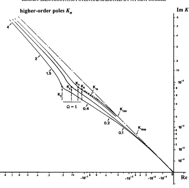
The behavior of these poles in the complex plane,
when • varies from 0 to above 1, is summarized in Figures 1 through 3. Using the usual notations, the
dominating Landau pole K• exists only for O >_ 1, lying in the upper left-hand quarter of the complex plane (Figure 1). The purely imaginary poles K 2 and
K_ 2 (for O < 1) are plotted in Figure 2, and the
higher-order poles K,in Figure 3, knowing that each pole K,is associated with its opposite conjugate according to the relationship K_,= - K,.
The function lie I can be expanded in form of an infinite sum of the principal parts at all poles of the complex plane (Mittag-Leffier series) under certain conditions [see Jeffreys and Swirles, 1966]. The most
important condition in our case is that the function
must be analytic at the origin. Thus this cannot be
strictly applicable with the variable K, because when
K -• 0 an infinity of poles K,and K_,crowd toward zero along the rays arg (K) = 3•/4 (Figure 3) and •/4
respectively. Indeed, the Mittag-Leffier expansion, for a given functionj(z) is
*' b b
f(z) :f(0) + • (----•"
+ ' )
(7)
where b, is the residue at the pole z, and the sum istaken from n = 1, ñ 2, ..., ñ
Instead of the variable K, let us consider z, as
defined in (4). Now, for any given •, one can check in the last term of (6) that 1/• l is analytic at z = 0 since Z' is continuously derivable in that area which corresponds to a pole-free region in K space when K-.•o. Obviously, here f(0)= I.
Using the properties of the function Z and its
derivatives, the residue is given by
1 Zn
2Zn
dz J z=z n
0 Kn
(8)
where e• is the usual cold plasma dielectric constant given by e• = 1- 0 -2.
Using (7) and (8), 1/el can be now expressed indifferently in function of either z or K
310 BEGHIN: ELECTROSTATIC POTENTIAL RADIATED BY A POINT SOURCE
Pole K 1
1.5 1.4 1.3 1.2 1.1 f 1.05 I _v =10' I 1.Ol I I I 1.001 \ \ \ .\ \ \ \ .9 .8 .7 .6 .5 .4 .3 .2 .15 8 6 4 2 6 4 2 .10 -• .10 '2 .10 '3 .10 '4 hn K ,.3 ..15 10 '2 8 6 4 2 10 '3 10 -4 10 's Re KFigure 1. Loci of pole K• in the complex plane as a function of the frequency (indicated by arrows) for
real Q (v = 0), and with a small imaginary part in order to understand the limit when v -- 0. Note the
unusual power-law scale which offers some advantage of the log scale with the possibility to cross the
origin from positive to negative values.
1 ' b ' b •=1+ •+ =-1+ 8z I-1 z I.1 z-z
'
•
'
K•
K
E
st. -E
(9)which could be considered as the Mittag-Leffier
expansion versus the variable K as well, with the significant difference that now the two first constant terms (independent from K) are definite, since them is
no reference to the undetermined value at the singular
point K = 0. To calculate the value of this constant,
either we compute directly the infinite sum for given
D, or better, we can derive an analytic expression. The result of the numerical computation is shown in Figure 4, for D = 1.01. The asymptotic behavior of the sum indicates clearly that
• b 3
"-
(]o)
Inl Z 4 8
while the direct Mittag-Leffier expansion with respect to K gives 1/•, the value attributed in (6) when K = 0
[Chasseriaux et al., 1972]. For the analytic demonstration of (10), let us consider the expansion
of lie I versus real z given by (9) when z • + oo. From
(6), knowing that z 2Z'(z) tends asymptotically to 1, we
BEGHIN: ELECTROSTATIC POTENTIAL RADIATED BY A POINT SOURCE lO ImK
Pole K•
_.• , ---10 v _10-3 =1 o 2- 1.5' I i .8- 10'L 1( 0 v=O -1(ß
,• ----!'--0.9
ß 0.5Pole/(-2
4 I I I g I I I I I ,4 ,6 ,8 1.5 2 4 6 8 15 1 lOFigure 2. Loci of poles K 2 and K. 2, in the same manner as those in Figure 1.
ReK
311
(11) This equation shows why the Mittag-Leffier expansion in K is in&finite, as long as the way to
approach
zero
is not determined.
Indeed,
the second
term of the right-hand side of (11) is not zero, as could be thought at first glance. To calculate this term, we
will remark that the contribution of the first finite-
order Landau poles (finite values of z, can be
neglected
while
z goes
to infinity.
Then,
the
asymptotic
approximation
of higher-order
poles
when
In l tends
to
infinity [Dertier and Simonen, 1969] can be used
I. I-- z. = - •/In
I• [•gn
(n)
+
,1
(12)
and the discrete sum can be transformed to integral,
putting
•n = x, with
x varying
from
0 to infinity.
After
312 BEGHIN: ELECTROSTATIC POTENTIAL RADIATED BY A POINT SOURCE /\ 4
higher-order poles K n
Im K 1.5 ! 0.2 o.1 .15 10 -1 8 10 -2 8 6 4 2 10 -3 10 -4ß
9 .8 .7 .6 .5 .4 .3
.2 .15
-10 -18 6 4
2
-10-
2 6 4 2 0-
-13
-10 -4 Re KFigure 3. Loci of poles K, for v = 0, knowing that the same family exists synunetrically for K_,, to the
imaginary axis.
" b 24 +16e z
,
.f
o (9 + 16
x 2e
x•
•)(z
•
4
+ 4x 2)
1 (13)4e
Similar calculation proves that the imaginary part is zero, completing the demonstration of (10).
The integrant in (1) is now well-defined everywhere in the complex plane. Then, changing k into - k in the
integral and using the dimensionless variables, we rewrite (1) in its final form
4•or
+3K.
2
o X+KnP
(14)
BEGHIN: ELECTROSTATIC POTENTIAL RADIATED BY A POINT SOURCE 313 50- 45- • = 1.01 3 4œ c -1 ß ß ß ß ß ß • ... ib ' ' 60 •ooo
Figure 4. Computed sum of the excitation coefficients of
Landau poles versus the order Inl, for Ca - 1.01.
Chasseriaux et al. [1972] by the term 3/4e• instead of l/e•.
3. Series Expansion of the Potential
The integral in (14) is an auxiliary function of sineand cosine integrals [Abramowitz and Stegun, 1972] defined as
f(K.p)
=
f sin
o x+K.p
x dx
= Ci (K,,O)
sin (K.p ) - si (K.p ) cos
(]5)It is a multivaluated function, as a cosine integral is, with the branch cut along the real negative axis, where there is no pole, according to the discussion in
previous section. Using the series expansions of each
individual function of (15), we obtain
f(K,p)=-•-
l+• (-1
q., (2q)!K• +
(16)
• (-1)' y +lnK,,p
-
--
•-0
r-• P '(2q+l)!
with the determination larg (K.)l < n, and where ¾ is
the Euler's constant y = 0. 5772156649 ....
Then, substituting this expression to the integral in (14), the potential is expressed on form of a series
expansion versus the variable p, with coefficients
(infinite sums over K, depending only on the frequency, plus a constant which is easily found to be 1, using (8) and (10). We get three different kinds of coefficients Inl
•+3
K +•
'
ß $•
I - t•: + 3K.I,I
I - t•: + 3K•
....
"
(17)
From considerations about the symmetry of poles,
that is, K• = - K.2* when f• > 1, K, = - K.,* for n > 2,
and knowing that K2 and K. 2 ( f• < 1) are purely
imaginary,
we deduce
that
the
even
coefficients
S2•
are
purely real, and the odd ones are purely imaginary,
while the coefficients L2• have both real and imaginary
parts due to In K,. Then, the real and imaginary parts
of (14) are
1,,
I
-- S --.
(2q)! •
•-• 2--/•e
(L•_•)]
(2q - 1)! n x •-0 (2q + 1)! p=l P (]8)respectively, where q>o is the free-space potential,
4•o = Q/nn eo r.
This is the desired series expansion of the potential versus the distance from the source with frequency dependent coefficients. One can see that the potential
tends to its vacuum value when p tends to zero. The
next point now is to determine the coefficients.
4. Calculation of the Coefficients $ and L For practical applications the coefficients given by (17) can be computed and tabulated once and for all
for every desired normalized frequency. Here we
propose to determine them analytically for better
314
BEGHIN:
ELECTROSTATIC
POTENTIAL
RADIATED
BY A POINT
SOURCE
The easier coefficients to determine are the coefficients
S. The first
one,
So,
is already
known,
as given
from
(10), that
is, So
= I - 3/4e•.
The
following
terms
are
obtained
by successive
derivation
of the dispersion
equation. Using (6) and (9), we can write
-- I --
Oz r Inl z z-z
---0
(19)
Forp
= 1 to 5, one
finds
from
(19)
after
some
algebra
2 • 3 2 • 4 2
Inl
•n
Inl
•n •
Inl
•n
(20)
' b 4 1 ' b 2V/-•(
1
+
Inl
Zn
•
Inl
Zn
Then,
from
(8) and
(20)
we
obtain
successively
$1=0 ;
I•p " b n
$P-
2
•7• zn
p+l$2=-1
; $3=-i•
• I•
2•• I•
2
$4=I
.a 2' $•=i • a(2+ ) (21)
2d z•Z dz •
---I
• it-1)'2'l'3'5'"t2q
- 1)v•'
dP
dr.
•:
r • fl• p(p-1)
1
[ _
z-
1 d
dz
r-I
p-I
Z
I
(22)we obtain
the
desired
recurrent
relationship
between
even coefficients, for q _> 3
$• (-1)q
=
fl•q-2
[ 2q-3
1-____S2 +... +
(-
1)q*•
1.3.5...(2q-3)
• 2q-2 S2q
-2 +
i• • (-l)q•-s
2 2•-•(q _ 3)!
[
2 (q-3)
Ss
+,,,
(-
1)q+•
2q-z
(q
- 3)! ]
(23) and a similar one for odd coefficients, which reads/•
1-$•.•
=
i -• 2
•-•
(q
- 1)!
2 (q-
1)
S2
+...
(-
1)q+•
2
q-•
•-• 'S2•_•
(q
- 1)l ]
-
A recurrent
expression
for
higher
orders
than
Ss
can
be
obtained from (19) and (20). For that we must use the
recurrent properties of the derivatives of the function
Z and apply
Leibniz's
theorem
to (19). Using
the
following relations
(-
1)q
•'•2q-4
[ 2q-5
S ---S s+ +
1.3.5...(2q-5) •
f12
"'
(-1)
'1'3'5"'(2q-5)
•,'•
2q-4 S2q
-I
] (24)
d
dz
zg+•
•+• =(-1
Z
I )q+•
22q+•
q.
is a polynomial
One
can
see
from
(21),
of degree
(23),
and
p-2 for fl, with all its
(24)
that
each
S•
(fl)
BEGHIN: ELECTROSTATIC POTENTIAL RADIATED BY A POINT SOURCE 315
to S•. For • • 0 we obtain
the limits
S2•
(0) = (-1)•
and S2•+• (0)= 0. Moreover, all S•'s are finite at • = 1. The coefficients L2• are more difficult to calculate
analytically due to the presence of logarithm of K, in
(17). However, the real part is quite easy to obtain,
using the symmetry properties of the poles K,. Indeed, for n •_ 3 and with the determination larg < we
have
Re (ha
K•) = Re (ln K_•) = In
•m ( m K•) •- • • - •m ( m K _•)
(25) and for fl > 1 the same relationship exists between the poles K• and K_:. Then, the contribution of the purelyimaginary pole K: being simply InK: = lnIgel + i•/2,
we get from (17)
Xe
(26)For • < I the contribution of K_: added to that of other
poles leads one to write INK_: = lnlK.:[ + i•/2 - i•. Then, we get
Re
(L
•) = • •---
2$•.•
-
K =2 21 - O=+3K_•
(t] < 1) (27)This result shows a discontinuity at Q = I which needs
some attention. First, let us estimate the limit of the second term in the right-hand side of (27) when • • 1. The solution of the dispersion equation e• (K,•) = 0 for the imaginary pole K.:, expressed as a power expansion for the cold plasma dielectric constant e•,
using the asymptotic expansion of Z' (z), reads
3K 2
-2 •[1 + • •
=
$
+ o
(28)
3 3
where e• tends to zero by negative value when Q • 1. Substituting in (27) the value of K_ 2 given by (28), we obtain
(fi<•l) (29)
It is clear from (29) and (26) that the continuity exists at • = 1, that is, when e• = 0, for all orders q except for the first one, q = 0, in which case Re (L0)
tends to - oo when • approaches I by lower values. On
the other hand, since S• = 0 after (21), we get Re (L0) = 0 for • > 1. This discontinuity at • - I is consistent with the usual behavior of a single charge-
induce3 potential, which exhibits a singular point at •
[see Rooy et al., 1972]. Since the singularity affects only the coefficient L0 associated with the first term of the power expansion for p of the dimensionless potential, given by (18), we see immediately that the resulting contribution to the actual potential • (r) is a constant independent of the distance r. Thus, for any configuration which must always satisfy the charge neutrality of the source (•Q+ = •Q_), this constant
disappears, as the singularity at •r does. In the
following we make the choice for the determination of
Re (L0) at • = 1 to be the same as for • > 1, that is, Re(Lo) = O.
The last coefficient to be determined now is
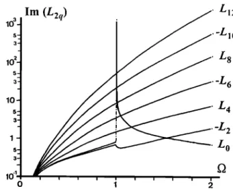
lm (L2•). The behavior of these coefficients versus the
frequency, as obtained by direct computation of the summation in (17) over a quasi-infinite number of
poles, is shown in Figure 5 for the first ones of the series. We notice that lm (L0) presents a discontinuity at • = I like the real part, growing to infinity when • tends to I from upper values. The consequence on the potential is the same, since lm (L0) corresponds also to the first order of p in the imaginary part of the power
lm (L2q)
L 12
-L•o L 8 5- a- -L 6•o
$2 .L4
•'
_L
2
1
LO
3-•o
'•- ,
....
, •
o 1 2Figure 5. Plot of the imaginary part of the first orders of
316 BEGHIN: ELECTROSTATIC POTENTIAL RADIATED BY A POINT SOURCE
expansion. Here we choose the determination at Q = 1, which corresponds to the finite limit when Q tends to 1
f•om lower values, so that, all other coefficients being finite for D = 1, both real and imaginary parts of the
potential are finite at (%.
There
is no simple
analytic
expression
for Im (L2•).
However, as shown in the Appendix, one can find a generating function for the first one of the series (Lo)
and a recurrent differential equation allowing in principle to calculate the others. But for practical
reasons it is more efficient and more accurate to compute and tabulate once and forever the coefficients
$ and L for a limited number of frequencies. Then, for the following we retain that this tabulation is performed using the analytic expressions for the
coefficients
S• and
Re(L2q
) and
direct
computation
for
Im(L2q).
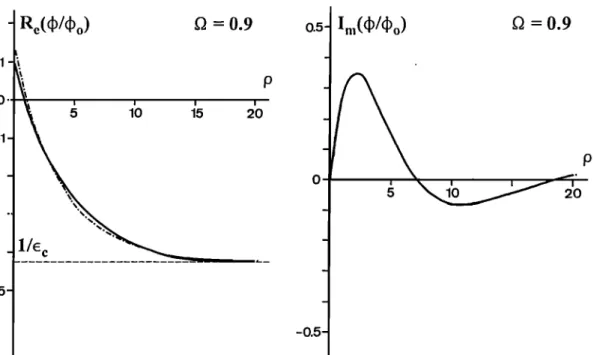
The computed values of the normalized potential,
using the series (18), are plotted in Figures 6 through
9, as a function of p from 0 up to 20, for D = 0.9, 1, 1.1, and 1.5, successively. The behavior of the
potential versus the distance is consistent with the
results of previous works in this domain, using direct
integration without approximation [e.g., BucMey,
1968]. The electrostatic response of the plasma is seen
as a strongly damped waveform, with a quasi-periodic shape visible only in the imaginary part for f• < 1, and
a more or less damped oscillation (the Langmuir wave)
in both real and imaginary parts, for Q < 1. Results
f•om the series (18) have been found identical to those obtained from direct numerical integration of (1),
except for the case D = 1, where the singular point
makes difficult the numerical integration.
Computation is made using double precision for the
coefficients and remains converging up to p --- 20, but
then requires orders of coefficients larger than q = 50. This is equivalent to the computation of the sine and cosine functions for large arguments, using their power expansion. It is the reason why the power series
expansion (18) is proposed to be used only for small distances, where usual approximations fail.
5. Comparison With the Landau Wave
Approximation
The Landau wave approximation [Chasseriaux et al., 1972] consists (1) to ignore the contribution of all higher-order poles; (2) to approximate the contribution
1
1-' o -1 -•- =0.9 P0.5
=0.95
1•
20
Figure 6. Real and imaginary parts of the normalized potential versus the normalized distance from the source, for G = 0.9, as obtained using the power expansion (solid line) and the Landau wave approx- imation (dashed line). Note that the approximation leads to an imaginary part equal to zero for Q_< 1.
BEGHIN: ELECTROSTATIC POTENTIAL RADIATED BY A POINT SOURCE 317
Re(•/•o)
• = 1
0.,5-o
'P
50-
0 5 10 15 20
Figure 7. Same as in Figure 6, for Q = 1.
of the pole K• for • > I by a slowly damped sine wave
and that of K_ 2 for f• < I to an evanescent wave; and
(3) to interpret the resulting potential as due to beating
between the cold plasma part (l/e c) and the
I '
Re(•,•
o)
Q = 1 1
ß
$_
l0
0 5 10 15 20
dominating Landau wave. This interpretation needs to be revised, considering that the potential obeys (14), where it could be thought that the cold plasma contribution should be 3/4e• and the warm
Q=I.1
Figure 8. Same as in Figure 6, for Q = 1.1. Here the imaginary part as given by the Landau wave approximation (dashed line) is not zero.
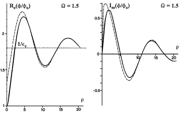
318 BEGHIN: ELECTROSTATIC POTENTIAL RADIATED BY A POINT SOURCE
Re(•,/4)o) • = 1.5
1
5•
Im(4)/4)o) • = 1.5
-0.5
P o
Figure 9. Same as in Figure 8, for fl = 1.5.
contribution should come from the infinite sum of Landau poles. In reality, this assumption is not
consistent with the fact that we are considering a Maxwellian thermal distribution independently of the
absolute value of the plasma temperature, which could be as low as we want.
Therefore, the correct approach is to evaluate the relative contributions between the dominating Landau
poles and the infinite series of higher-order poles.
Since these higher-order poles produce highly damped waves, it is generally believed, somewhat incorrectly, that their contribution should be negligible at large
distances from the source. In order to evaluate that let
us consider 9 -• oo in (14). The paradox comes from
the fact that for any finite value of 9, there is still an infinity of poles K, such as oK,-• 0, the contribution
of which could be not negligible since their damping
actually remains low. To solve this question, it is
necessary to come back to the variable z, the only one
for which the Mittag-Leffier expansion is definite.
Separating the contributions of the higher-order poles from that of the main ones (K• and K.2) , we rewrite (•4)
b,, sin x dr
p• Z n + •
f(K.p) (30)
When p g• tends to infinity, for a given finite value of
x, we get from (13)
n2g +p•
4e
•
(31)
Moreover, since the main contribution to the integral comes from small values of x, the more x approaches to zero, the more (31) is valid. Then, after the trivial integration of sin x/x we obtain the result
BEGHIN: ELECTROSTATIC POTENTIAL RADIATED BY A POINT SOURCE 319
I 2
'0 ee X n=-2
1-O
2
+3K•
(32)
which basically validates the so-called Landau wave
approximation proposed by Chasseriaux et al. [ 1972], but with a quite different meaning, since now the contribution of highly damped waves is included for 25% in the term 1/•. Except in the vicinity of fl • 1, where the pole K• lies near the negative real axis, the asymptotic behavior of the function f (K,), when p tends to infmity, is decreasing like 1/K, [Abramow•tz and Stegun, 1972]. Thus we see immediately from (32) that the asymptotic value of the potential at large distances is that of the cold plasma, which is visible in Figures 6 through 9. This is consistent with the fact that more the temperature decreases, as Xo does, the more the normalized distance r/XD tends to infinity.
The success of the Landau wave approximation for
practical applications comes from a larger range of validity than simply seen from its asymptotic behavior. Indeed, for fl • 1, until K• p lies near the negative real
axis, the sum f (K•p) + f (K.2p) reduces to
• exp (iK•p), even at relatively small distance [Simonen, 1966]. For fl < 1 the contribution of the imaginary pole K.2 is nearly an evanescent wave, which has been proposed by Chasseriaux et al. [1972] to be represented in (32) by the crude approximation f(r.2P) "• • exp (-p [K.2I), properly chosen to achieve
an analytic continuation through • = 1. Thus, the conventional Landau wave approximation, used with
some success at•r comparison with experimental data
of large-size mutual impedance probes, reads
4• I
2K/
• -- +
exp
( iKr p ) ; (pO
4)0 e I O
½ --2 3K/
(33)
with
Kv
= K, for fl > 1 and
Kv
= -K.
2 for fl <1.
The comparison between the results obtained from the analytic series (18) and the approximation given by (33) is shown in Figures 6 through 9. As a general feature, we see that for the real part of the potential, the Landau wave approximation is quite satisfactory for p larger than about 15, as well as for the imaginary part when fl > 1. But, obviously the approximation is
unable to produce the strongly damped waveform of the imaginary part when O (_ 1
6.
Application to Mutual Impedance
ProbesModeling of mutual impedance response is one of the main applications of this work, as the measured response, compared to the theoretical one, is used for plasma diagnostic. We show in Figure 10 an example of the mutual impedance response expected to be
obtained from a device developed for the Russian MARS 96 mission. For an electron density of
500 e/cm 3 and temperature of 1000 K in the Martian
ionosphere, which are typical values around 300 km
of altitude [Hanson et al., 1977], we get XD • 10 cm.
The simplified model of the device is made of two single charges +Q and -Q located 30 cm each other and a double-point receiving dipole 1-m long (see inset of Figure 10), so that we are everywhere in conditions
such as p < 10. As long as the sensor-receiver system is a high-impedance coupling one, and the source a
constant-current generator [B•ghin et al., 1982], the induced voltage V• in each sensor is the same as the space potential induced by the two charges at this location, and the charge distribution in the source is the same in the plasma as in vacuum. Then, the mutual impedance is defined by
Z AV
-- =
•'
(34)
z0
where
A Vv
is the
differential
voltage
between
the
two
receiving sensors (V• - V2) in the plasma, A V 0 is its free-space value, and V• or V: are given by
V,.
= • s•gn
(Qj)
4•,(Po.)
(35)
where p o. is the normalized
distance
between
the
charge
Qs
and
the
receiving
sensor
of index
i.
The modulus and the phase of Z/Zo are plotted in Figure 10, as calculated using the power expansion (solid line) and the Landau wave approximation
(dashed line). The exact solution exhibits a well-
marked maximum for the phase very close to • = 1,
while the modulus reaches a flat maximum around
320 BEGHIN: ELECTROSTATIC POTENTIAL RADIATED BY A POINT SOURCE _ _ _ 0 V2 l-<: ... :)-I '<:- ':)"t V1 30 cm •'D = 10 cm -o 180ø... .. ,. 120- - 60- ., 0- ., (z/z o )
Figure 10. Theoretical normalized response, in modulus and phase, of an idealized mutual impedance probe made of two single charges and two potential sensors, for •'O = 10 cm. Shown are the exact value using the power expansion (solid line) and the Landau wave approximation
(dashed line).
determination
of •or is consistent
with the measure-
ments performed at large Debye lengths [D•cr•au et
al., 1978]. However, a more realistic modeling would
be necessary in the attempt to calculate the true probe response, considering the actual shape and taking account of the charge distribution induced among all conductive surfaces. The method consists of solving
(35) on a three-dimensional finite-element grid array, with limit conditions on constant potential surfaces
which satisfy the charge neutrality equation. The power series expansion theory is well adapted for such a computation as long as the considered distances are
shorter than •- 15 Zo. At larger distances the Landau
wave approximation would be used.
7. Conclusion
A revised mathematical treatment of the classical
problem of the electrostatic potential induced by point
source in a Maxwellian isotropic plasma has been
presented. The new formalism for Mittag-Lefler
expansion of the plasma function l/e• leads to a
different expression of the potential from that
previously considered. The first result is a better understanding of the real contribution of the
higher-order Landau poles, which has been found to be included in what was interpreted before as the cold
plasma contribution. Then, using the Mittag-Lefler series, the syrmnet• properties of the plasma dispersion function and the expansion of the auxiliary functions of the family of exponential integrals, the
power expansion for the potential has been obtained, with coefficients depending only on the frequency. Moreover, considerations about the asymptotic behavior of this expansion at large distances allows one to justify the classical Landau wave approximation in such conditions. The power series expansion for the potential reveals to be of considerable practical interest for exact computation and probe modeling when sises are smaller than about 15 to 20 )•.
Appendix
By integration of the quantity 1/•- I along the negative K axis (where there is no pole), performed
using both (6)' and (9), we obtain after some
development
0
Lo
= 0 f z,<x>
(AI)which is a finite integral except for fi = 1, due to the pole for x infinite. If we extend this integral along a closed contour including the positive imaginary axis y, since Z' (iy) turns to be purely real, we recover the result given by (26) and (27) for q = 0, that is, the real part of Lo is the residue for the imaginary pole
iy = •/(K.2 •/2) when •<l. Using the syrmnetw
properties of Z', we can also writef
- [•-lm
f•-x•Z/(x)
BEGH1N: ELECTROSTATIC POTENTIAL RADIATED BY A POINT SOURCE 321
For fl-O the main contribution of the integrant occurs around x = 0; then, using the first order expansion of Z', we obtain
2 2
a-o)
(A3)
For fl > 1, expanding the integrant versus 1/fl 2, one
obtains the following asymptotic expansion
I f * [z'(x)F
x&
(A4)
where the constants C• are computed once and for all.
The first ones can be determined analytically after a quite tedious effort using the power expansion of the function Z' and the following relation
o
&
- x Z'fx)F
(A7)
where the coefficients B• are constants computed once and for all, as the previous series C r Values of these
coefficients for both series are listed in Table A 1, up to p=10.
Having obtained an analytic expression for Im(Lo), the problem now is to deduce from it the other
coefficients Im(L2•), using a recurrent relationship.
Unfortunately, these coefficients do not obey a simple recurrent law do the coefficients S. Starting from the definition Lo in (17) and using the following relation
2
dK,, K. 1-D •+K.
2
dD D l-f12+3K.
(A8)we obtain the differential recurrent equation between
the coefficients L and S.
• (-l)•"2•'•(n!)
2 2 In(1
V•) (A5)
0
(2. + 1)!
V/•
The first three terms of the series C• are
3 D-•'- d
•
+
dD
(Lrø-
D ) =[P+3-
(P+I)D]Lr
dL (A9)g (g
2
- 1) dD
Co=
1 ; C,
= 3
In
(1
+V/•)
I 31 la(I+v• )
C'2 = --- +6
Ill •/•
27
(A6)One can notice that the coefficients of the sum in
(A4) are close to those of the expansion of the function
[•2/(•2-1)]½1, in accordance with the behavior of
Im(Lo), shown in Figure 5, as well as when fl tends to
infinity, as when approaching 1.
For 0 < fl < 1 one can find a converging power
expansion of Im(Lo) for the variable rl = 1/2 - f12,
with rl varying from 1/2 to -1/2, using the fact that 11/2-x2Z'(x)[ >_ 1/2. One obtains
Table
A1. First
Coefficients
of L2q
Series
0 1. 1 0.4348378 2 0.3091567 3 0.2503295 4 0.2151077 5 0.1911903 6 0.1736555 7 0.1601198 8 0.1492772 9 0.1403465 10 0.1328291 0.644588 -0.098254 0.120390 -0.072666 0.118156 -0.079526 0.167482 -0.099190 0.289021 -0.11875 0.57312
322
BEGHIN: ELECTROSTATIC POTENTIAL RADIATED BY A POINT SOURCE
which allows one, in principle,
to calculate
higher-order
terms
starting
from
the
power
expansions
of L0. For instance,
we obtain
for L 2 the
following
expressions
-
]
E p+l
Cr-,-C
r
(f•>l)
;,-• 3p f• •'-•1 •
lm
(L:)
=
i f•
v• {I
.
3V/• r-•
• 2
•
(A10).(
(1
-2
n2)r
[2 2(02-1)]
•,-o k+l
(0< 1)
where tz =-0.058053 and 13 =-0.4468417 are
integration
constants
determined
numerically
from
the
direct
computation
of L:.
However,
for
practical
reasons,
the
direct
computa-
tion
of coefficients
L for a limited
number
of frequen-
cies
is more
efficient
than
the
analytic
method,
though
the
number
of data
to be stored
is significantly
larger.
References
Abramowitz, M., and I. A. Stegun, Handbook of Math-
ematical Functions, Dover, Mineola, N.Y., 1972.
B6ghin,
C.,
Excitation
de
la r6sonance
hybride
basse
(LHR)
par sonde quadripolaire fi bord d'une fus6e, in Space
Research Xl, Akademie-Verlag, Berlin, 1071, 197 I.
B6ghin, C., and R. Debrie, Characteristics of the electric
field far from and close to a radiating antenna around the
lower hybrid resonance in the ionospheric plasma,
J. Plasma Phys., 8, 287, 1972.
B6ghin, C., J. F. Karczewski, B. Poirier, R. Debrie, and N. Massevitch, The ARCAD-3 ISOPROBE experiment for high time resolution thermal plasma measurements,
Ann. Geophys., 38, 615, 1982.
Buckley, R., Radio frequency properties of a plane grid capacitor immersed in a hot collision-free plasma, d.
Plasma Phys., 2, 339, 1968.
Chasseriaux J. M., R. Debrie, and C. Renard, Electron
density and temperature measurements in the lower
ionosphere
as
deduced
from
the
warm
plasma
theory
of
the quadrupole probe, d. Plasma Phys., 8, 231, 1972. D6cr6au, P.M. E., C. B6ghin, and M. Parrot, Electron
density and temperature, as measured by the mutual impedance experiment on board GEOS-I, Space Sci.
Rev., 22, 58 l, 1978.
D6cr6au, P.M. E., S. Pertaut, H. de Feraudy, L. Matson, and O. Randriamboarison, Electron density and temperature
in the cusp and polar cap regions: Contributions from the
wave and particle experiment on Viking, in Modeling Magnetospheric Plasma Geophys. Monogr. Ser., vol.
62, edited
by G. R. Wilson,
p 112,
AGU,
Washington,
D.C., 1991.
Dertier, H., Transients in electron plasmas, in Proc. Int. Conf Phenom. Ionized Gases 2nd, 282, 1966.
Dertier, H., and T. C. Simonen, Higher-order Landau
modes, Phys. Fluids, 12, 269, 1969.
Fried,
B. D., and
S. D. Conte,
The
plasma
dispersion
function, Academic, N.Y., 196 I.Grard, R. J. L., Coupling between two electric t aerials in a warm plasma, Alta Freq., 38, 97, 1969.
Han•n, W. B., S. Sanatini, and D. R. Zuccaro, The Martian
ionosphere
as
observed
by
the
Viking
retarding
potential
analysers, d. Geophys. Res., 82, 4351, 1977.Jeffreys, H., and B. S. Swirles, Methods of Mathematical Physics, 3rd ed., Cambridge University Press, •N. Y.,
1966.
Landau, L., On the vibrations of the electron plasma, d.
Phys. Moscow, 1 O, 45, 1946.
Navet, M., and P. Bertrand, Multiple "water-bag" model and
Landau damping, Phys. Lett., 34A, 117, 1971.
Pottelette,
R., M. Hamelin,
J. M. Illiano,
and
B. Lamb•ge,
Interpretation of the fine structure of electrostatic wavesexcited in space, Phys. Fluids, 24, 1517, 1981.
Rooy, B., M. R. Feix, and L. R. O. Storey, Th6orie de la sonde quadripolaire en plasma chaud isotrope, Plasma
Phys., 14, 275, 1972.
Simonen, T. C., Landau waves, Rep. SUIPR 100, Inst. for
Plasma Res., Stanford Univ., Stanford, Calif., 1966.
Storey,
L. R. O.,
M.P. Aubry,
and
P. Meyer,
A quadripole
probe for the study of ionospheric plasma resonances, in
Plasma
If/aves
in Space
and
in the
Laboratory,
vol. 1,
edited
by
J. O. Thomas
and
B. J. Landmark,
University
Press, Edinburgh, Scotland, p. 303, 1969.
C. B6ghin, Laboratoire de Physique et Chimie de
YEnvironnement, CNRS, 45071 Orl6ans Cedex, France. (e- mail' span cnesta: :begbin or cbeghin•cnrs-orleans.fr)
(Received June 30, 1994; revised November 15, 1994;