Publisher’s version / Version de l'éditeur:
IEEE Transactions on Ultrasonics, Ferroelectrics and Frequency Control, 57, 1, pp. 189-192, 2010-01-01
READ THESE TERMS AND CONDITIONS CAREFULLY BEFORE USING THIS WEBSITE.
https://nrc-publications.canada.ca/eng/copyright
Vous avez des questions? Nous pouvons vous aider. Pour communiquer directement avec un auteur, consultez la
première page de la revue dans laquelle son article a été publié afin de trouver ses coordonnées. Si vous n’arrivez pas à les repérer, communiquez avec nous à [email protected].
Questions? Contact the NRC Publications Archive team at
[email protected]. If you wish to email the authors directly, please see the first page of the publication for their contact information.
NRC Publications Archive
Archives des publications du CNRC
This publication could be one of several versions: author’s original, accepted manuscript or the publisher’s version. / La version de cette publication peut être l’une des suivantes : la version prépublication de l’auteur, la version acceptée du manuscrit ou la version de l’éditeur.
For the publisher’s version, please access the DOI link below./ Pour consulter la version de l’éditeur, utilisez le lien DOI ci-dessous.
https://doi.org/10.1109/TUFFC.2010.1397
Access and use of this website and the material on it are subject to the Terms and Conditions set forth at
Ultrasonic probes having three orthogonal polarizations
Jen, C. -K.; Wu, K. -T.; Kobayashi, M.
https://publications-cnrc.canada.ca/fra/droits
L’accès à ce site Web et l’utilisation de son contenu sont assujettis aux conditions présentées dans le site LISEZ CES CONDITIONS ATTENTIVEMENT AVANT D’UTILISER CE SITE WEB.
NRC Publications Record / Notice d'Archives des publications de CNRC: https://nrc-publications.canada.ca/eng/view/object/?id=a4affbed-39d2-4425-b538-f3087fff2abf https://publications-cnrc.canada.ca/fra/voir/objet/?id=a4affbed-39d2-4425-b538-f3087fff2abf
Ultrasonic Probes Having Three Orthogonal Polarizations
C. -K. Jen1, K. -T. Wu2 and M. Kobayashi1
1Industrial Materials Institute, National Research Council of Canada, Boucherville, QC J4B 6Y4, Canada
2Department of Electrical and Computer Engineering, McGill University, Montreal, QC, H3A 2A7,
Canada
ABSTRACT
Ultrasonic probes which can simultaneously generate and receive two orthogonal polarized shear (S⊥
and S//) and longitudinal (L) waves in screw shape have been presented. Thick piezoelectric films are
directly fabricated onto the heads of such probes as L wave integrated ultrasonic transducers. S⊥ and S//
waves are obtained using mode conversion method. Potential applications of such probes are discussed.
KEY WORDS: Ultrasonic birefringence, integrated ultrasonic longitudinal and shear wave transducer, nondestructive testing, material characterization
Thickness measurement including corrosion and erosion monitoring using ultrasonic technology is routinely used in industries at room or elevated temperatures. Certainly high accuracy is desired. However, factors affecting the measurement accuracy using ultrasound can come from texture [1], [2], stress [1], [3]-[5], etc which all alter the ultrasonic velocities in the material. In the other word, if the thickness of the material is given, ultrasonic velocity variations may be applied to measure the stress and texture [1]-[5]. In Reference [1] effects of statically applied stresses on the velocity of ultrasound in the material were studied at room temperature using the combination of three standard alone ultrasonic
transducers (UTs); namely one longitudinal (L), one vertically polarized shear (S⊥) and one horizontally
to measure the residual stress or texture in the textured steel [2], [3]. Furthermore acoustic birefringence
involving just S⊥ and S// measurements were also reported [6]. Some of experiments for the above
mentioned studies were performed using electromagnetic acoustic transducers (EMAT), for example, in References [3] and [4]. However, EMAT cannot be used to measure the non-conducting substrates, and may be bulky and have low sensitivity.
Let a Cartesian coordinate system be xyz with the z direction being the through thickness direction or normal direction to a plate of the material, and x and y being the rolling and transverse directions of a plate such as steel, the stress-free velocities for the propagation along the z direction only
depend on the texture coefficients W400 and W420 [2]-[5] and are given in an Voight [7] approximation [3]
by
⎥
⎥
⎦
⎤
⎢
⎢
⎣
⎡
−
−
=
=
35
2
16
5
1
2
/
400 2 11 2 , 2 2W
C
C
t
h
V
Lρ
dLπ
ρ
⎥
⎥
⎦
⎤
⎢
⎢
⎣
⎡
⎥
⎦
⎤
⎢
⎣
⎡
−
−
+
=
=
⊥ ⊥ 400 420 2 44 2 S , 2 22
5
35
2
16
5
1
/
t
C
C
W
W
h
V
Sρ
dπ
ρ
(1)⎥
⎥
⎦
⎤
⎢
⎢
⎣
⎡
⎥
⎦
⎤
⎢
⎣
⎡
+
−
+
=
=
2 44 2 400 420 // S , 2 2 //2
5
35
2
16
5
1
/
t
C
C
W
W
h
V
Sρ
dπ
ρ
where VL, VS⊥ and VS// are the ultrasonic velocity and td,L, td,S⊥ and td,S//, the ultrasonic time delay of L, S⊥
and S// waves in the substrate with a thickness of h, and C = C11 - C12 - 2C44, respectively. Let the
polarization of S// wave be along the x direction and that of S⊥ be along the y direction during the
experiments. Using Eq. (1), if one adopts an averaging method and knows the signal crystal elastic
constants Cij [2]-[5] and the density ρ of the material in Equation (1), two texture coefficients, W400 and
W420, can be calculated from the measured ultrasonic time delays, td,L, td,S⊥ and td,S//. Also an accurate
measurement of the substrate (plate) thickness, h that is corrected for texture variations may be made [2].
Recently, integrated ultrasonic transducers (IUTs) have been made using the sol-gel based fabrication process [8], [9] consists of six main steps: (1) preparing high dielectric constant lead-zirconate-titanate (PZT) solution, (2) ball milling of piezoelectric PZT powders to submicron size, (3) sensor spraying using slurries from steps (1) and (2) to produce a layer of PZT composite (PZT-c) film, (4) heat treatment to produce a solid composite PZT-c film, (5) corona poling to obtain piezoelectricity, and (6) electrode painting or spraying for electrical connections. Steps (3) and (4) are used multiple times to produce proper film (IUT) thickness for optimal ultrasonic operating frequencies. It is the objective to use such IUTs to achieve L UTs. The typical PZT-c film thickness in this study is 75 µm. Typically, the
measured d33 of this PZT-c film is about 30 x 10-12 m/V, the Kt about 0.2, the capacitance and the
dissipation factor at 1 kHz are about 0.75 nF and 0.03, respectively, the relative dielectric constant about
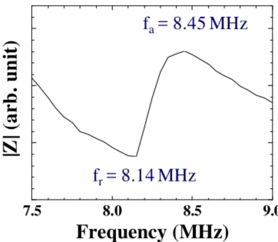
320, the density 4400 kg/m3 and the L wave velocity about 2200 m/s. A typical impedance Z chart
around the center frequency 8 MHz of a PZT-c film is shown in Fig. 1 in which fa and fr are the measured
anti-resonance and resonance frequency, respectively . Such IUTs has been operated with a center frequency ranging from 4 to 30 MHz. Their ultrasonic signal strength and bandwidth is comparable to those of the commercially available broadband UTs with backing, however, IUTs can be used at high temperatures [9]. 7.5 8.0 8.5 9.0
|Z
| (
a
rb
.
un
it
)
Frequency (MHz)
f
r= 8.14 MHz
f
a= 8.45 MHz
Fig. 1. A typical impedance chart around the center frequency 8 MHz of a PZT-c film.
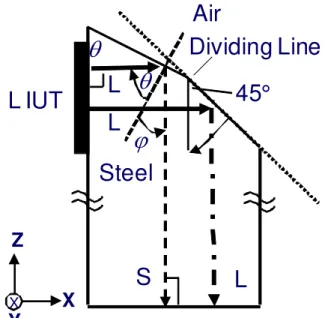
The mode conversion from L to S waves due to reflection at a solid-air interface, as shown in Fig. 2, was reported [10], [11]. It means that the L wave IUT together with L-S mode conversion caused by
the reflection at a solid-air interface can generate S waves effectively and be used as an S wave probe. Our approach considers a simple way to fabricate the L wave IUT and let the L IUT be in a plane parallel
to axial direction of the probe as shown in Fig. 2. The only criterion is that in Fig. 2 Cot θ is equal to Vs /
Vl so that the mode converted shear waves will propagate in the direction parallel to the axial direction of
the probe. In this study, a mild steel with the L wave velocity Vl = 5914 m/s and S wave velocity Vs =
3215 m/s was used as the probe material. Therefore one can obtain θ = 61.5°. Using the energy reflection
coefficient formula reported in Reference [11] the calculated energy conversion rate at θ = 61.5° is 97.2%
that is only 0.5% smaller than the maximum conversion rate at θ = 67.4°. In Fig. 2 a 45° angle is also
made for the reflection of L wave along the axial direction of the probe as well. The arrangement shown in Fig. 2 enables both L and S waves propagate together along the axial direction of the probe.
Steel
ϕ
θ
L IUT
L
45°
S
L
θ
Dividing Line
L
X
Z
Y
XAir
Fig. 2. Reflection and mode conversion with an incidence of L wave at a solid-air interface.
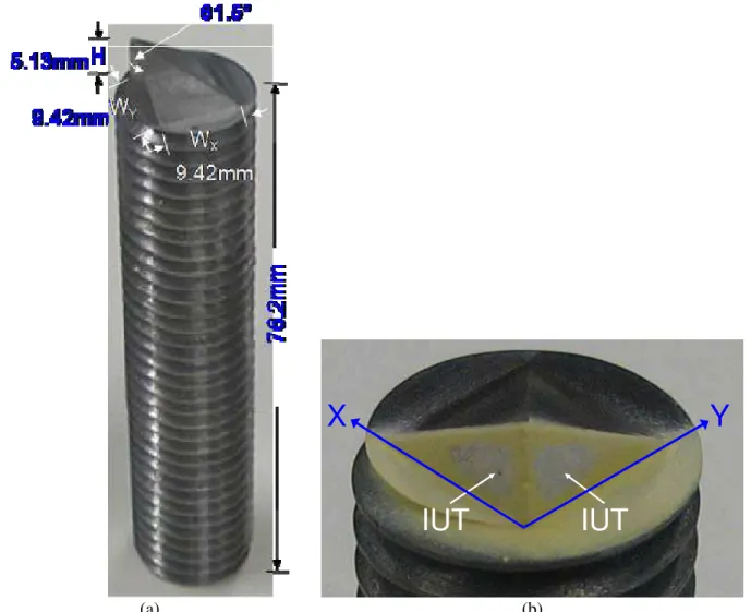
Using the L to S wave mode conversion principle shown in Fig. 2 if one would like to generate
two shear waves with orthogonal polarizations (birefringence) simultaneously, then θ = 61.5° will be
made at two orthogonal edges as shown in Fig. 3. Fig. 3(a) shows an integrated probe having two
polarizations and the zoomed probe head is presented in Fig. 3(b). Let one S be the S⊥ polarized in Y
measured ultrasonic signal S⊥n and S//n, respectively reflected from the end of the probe in time domain
and pulse-echo mode at room temperature where the time delay of Sn is that of the nth trip S echo through
the probe length plus that of the L wave travelling through the length from L IUT to the steel/air interface.
The signal SS indicated in Fig. 3(b) is a spurious signal which probably comes from the multiple
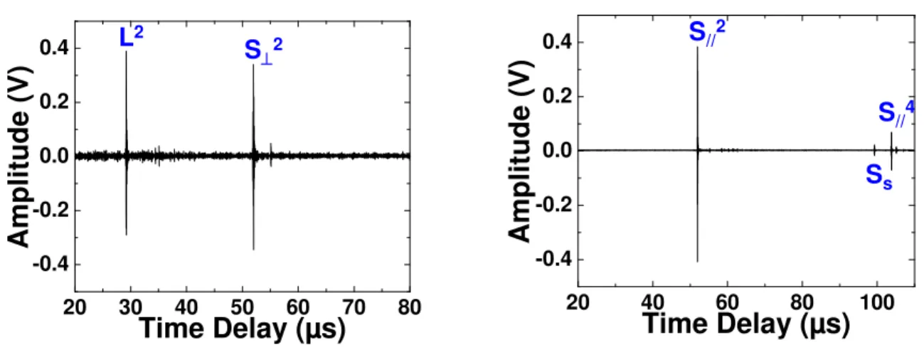
reflections of L or S waves from an undetermined boundary. The measurement results shown in Figs. 4(a) and 4(b) can be made simultaneously using a two-channel ultrasonic system. During the top electrode fabrication for two IUTs shown in Fig. 3(b), the area of the top electrode and position can be adjusted so
that the amplitude ratio of the reflected S⊥2 and S//2 can be adjusted. The center frequency and 6 dB
bandwidth of the S⊥2 and S//2 signals are 12 MHz and 11 MHz, and 13.4 MHz and 12 MHz, respectively.
Their SNRs are 36.1 dB and 36.6 dB, respectively. It is noted that such probe may be used as an ultrasonic interferometer which is sensitive to, for example, the anisotropy of the material to be measured, which induces a difference in particle displacement direction or velocity or both between two shear wave propagations along the material.
(a)
IUT
IUT
X
Y
(b)
Fig. 3. (a) An integrated S wave probe having two polarizations (S⊥ and S//) and (b) zoomed probe head
having two IUTs.
20 40 60 80 100 -0.4 -0.2 0.0 0.2 0.4
Am
pl
itude (V)
Time Delay (µs)
S
⊥2S
⊥4S
s (a) 20 40 60 80 100 -0.4 -0.2 0.0 0.2 0.4Amplitude (V)
Time Delay (µs)
S//2 S//4 Ss (b)Fig. 4. Ultrasonic signal in time domain of the (a) S⊥ and (b) S// wave generated by the L IUTs shown in
Fig. 3(b) reflected from the end of the probe at room temperature.
If a probe is desired to generate and receive L and S⊥ and S// signals simultaneously, then one side
of the probe shown in Figs. 3(a) and 3(b) can be modified according to the schematic shown in Fig. 2 to achieve such a purpose. In fact, only a slanted surface with an angle 45° is added at such side to reflect the L wave generated by the L IUT or the L wave coming from the reflection at the end of the probe as shown in Fig. 2. Fig. 5(a) shows the integrated probe having three polarizations and zoomed probe head is
given in Fig. 6(b). Figs. 6(a) and 6(b) show the measured ultrasonic signal Ln and S⊥n and S//n,
respectively in time domain and pulse-echo mode at room temperature from the end of the probe. The
time delay of Ln is that of the nth trip L echo through the probe length plus that of the L wave travelling
through the length from L IUT to the 45° steel/air interface. The measurements results shown in Figs. 6(a) and 6(b) can be carried out simultaneously using a two-channel ultrasonic system. During the top electrode fabrication for the device shown in Fig. 5(b), the area of the top electrode and position can also
be adjusted so that the amplitude ratio of the reflected L2, S⊥2 and S//2can be varied. The center frequency
and 6 dB bandwidth of the L2, S⊥2 and S//2signals are 19.1 MHz and 17 MHz, 17 MHz and 16 MHz, and
(a)
IUT
IUT
Y
X
(b)
Fig. 5. (a) An integrated probe which can generate and receive L and S⊥ and S// waves simultaneous and
(b) zoomed probe head having two IUTs.
20 30 40 50 60 70 80 -0.4 -0.2 0.0 0.2 0.4
Amplitude (V)
Time Delay (µs)
S⊥2 L2 (a) 20 40 60 80 100 -0.4 -0.2 0.0 0.2 0.4Amplitude (V)
Time Delay (µs)
S
//2S
//4S
s (b)Fig. 6. Ultrasonic signal in time domain of the (a) L and S⊥ and (b) S// wave generated by the L IUTs
In conclusion, integrated ultrasonic S⊥ and S// (birefringence) and L, S⊥ and S// probes have been
presented. They were fabricated onto the heads of steel rods in screw shape through a sol-gel spray technique. The typical PZT-c film thickness in this study is 75 µm. Mode conversion from L to S waves and reflection from a 45° slope for L waves have been used. All the above mentioned probes were operated at room temperature with a center frequency of 12 – 19 MHz, 6 dB bandwidth of 11 – 17 MHz, and SNR of more than 23 dB. It is noted that these IUTs can operate up to more than 150 °C [11] and 400 °C if bismuth titanate instead of PZT powders are used [9]. Such probes may be used to measure
thickness of a sample accurately with a correction of texture including texture coefficients such as W400
and W420. The stress applied to the probe, for example, in screw form, may be also measured. Because
they can sustain high temperatures, they may be also used on-line to measure Young's modulus, Shear modulus and anisotropy of the molded or casted parts during polymer injection molding and light weight metal die casting.
ACKNOWLEDGMENT
The authors are grateful to J.-F. Moisan for his technical assistance. Financial support from the Natural Sciences and Engineering Research Council of Canada is acknowledged.
REFERENCES
[1] R.H. Bergman and R.A. Shahbender, “Effect of statically applied stresses on the velocity of propagation of ultrasonic waves,” J. Applied Phys., vol. 29, no.12, pp. 1736-8, 1958.
[2] A. Moreau, D. Levesque, M. Lord, M. Dubois, J.-P. Monchalin, C. Padioleau and J.F. Bussiere, “On-line measurement of texture, thickness and plastic strain ratio using laser-ultrasound resonance spectroscopy,” Ultrasonics, vol. 40, no.10, pp. 1047-1056, 2008.
[3] D.R. Allen and C.M. Sayers, “The measurement of residual stress in textured steel using an
ultrasonic velocity combinations techniques,” Ultrasonics, vol. 22, no.4, pp. 179-188, 1984.
[4] R.B. King and C.M. Fortuko, “Determination of in-plane residual stress states in plates using horizontally polarized shear waves,” J. Appl. Phys., vol. 54, no.6, pp. 3027-35, 1983.
[5] M. Hirao, K. Aoki and H. Fukuoka, “Texture of polycrystalline metals characterized by ultrasonic velocity measurements,” J. Acoust. Soc. Am., vol. 81, no.5, pp. 1434-1440, 1987.
[6] K. Goebbels and S. Hirsekorn, “A new ultrasonic method for stress determination in textured materials," NDT&E Int’l, vol. 17, no.6, pp. 337-341, 1984.
[7] W. Voigh, Lehrbuch der Kristallphysik, Leipzig, Teubner. 1928.
[8] D. Barrow, T.E. Petroff, R.P. Tandon and M. Sayer, “Chracterization of thick lead-zirconate titanate films fabricated using a new sol gel process,” J. Apply. Phys., vol. 81, no.2, pp. 876-881, 1997. [9] M. Kobayashi and C.-K. Jen, “Piezoelectric thick bismuth titanate/PZT composite film transducers
for smart NDE of metals,” Smart Materials and Structures, vol. 13, no.4, pp. 951-956, 2004.
[10] M.O. Si-Chaib, H. Djelouah and M. Bocquet, “Applications of ultrasonic reflection mode conversion transducers in NDT,” NDT&E Int’l, vol. 33, no.2, pp. 91-99, 2000.
[11] C.-K. Jen, Y. Ono and M. Kobayashi, “High temperature integrated ultrasonic shear wave probes,”