Publisher’s version / Version de l'éditeur:
Technical Report, 2009-01-01
READ THESE TERMS AND CONDITIONS CAREFULLY BEFORE USING THIS WEBSITE.
https://nrc-publications.canada.ca/eng/copyright
Vous avez des questions? Nous pouvons vous aider. Pour communiquer directement avec un auteur, consultez la
première page de la revue dans laquelle son article a été publié afin de trouver ses coordonnées. Si vous n’arrivez pas à les repérer, communiquez avec nous à PublicationsArchive-ArchivesPublications@nrc-cnrc.gc.ca.
Questions? Contact the NRC Publications Archive team at
PublicationsArchive-ArchivesPublications@nrc-cnrc.gc.ca. If you wish to email the authors directly, please see the first page of the publication for their contact information.
NRC Publications Archive
Archives des publications du CNRC
For the publisher’s version, please access the DOI link below./ Pour consulter la version de l’éditeur, utilisez le lien DOI ci-dessous.
https://doi.org/10.4224/18227283
Access and use of this website and the material on it are subject to the Terms and Conditions set forth at
International Organization for Standardization (ISO) Thermal Manikin Working Group Round Robin Testing of Thermal Resistance of Suits
Mak, L.; Hackett, P.
https://publications-cnrc.canada.ca/fra/droits
L’accès à ce site Web et l’utilisation de son contenu sont assujettis aux conditions présentées dans le site LISEZ CES CONDITIONS ATTENTIVEMENT AVANT D’UTILISER CE SITE WEB.
NRC Publications Record / Notice d'Archives des publications de CNRC: https://nrc-publications.canada.ca/eng/view/object/?id=0cee8d19-e04a-4abe-9864-9341dc676967 https://publications-cnrc.canada.ca/fra/voir/objet/?id=0cee8d19-e04a-4abe-9864-9341dc676967
National Research Council Canada Institute for Ocean Technology Conseil national de recherches Canada Institut des technologies oc ´eaniques
TR-2009-10
Technical Report
International Organization for Standardization (ISO)
Thermal Manikin Working Group Round Robin Testing of
Thermal Resistance of Suits.
DOCUMENTATION PAGE REPORT NUMBER
TR-2009-10
NRC REPORT NUMBER DATE
May 2009
REPORT SECURITY CLASSIFICATION
Unclassified
DISTRIBUTION
Unlimited
TITLE
INTERNATIONAL ORGANIZATION FOR STANDARDIZATION (ISO) THERMAL MANIKIN WORKING GROUP
ROUND ROBIN TESTING OF THERMAL RESISTANCE OF SUITS AUTHOR(S)
Lawrence Mak and Peter Hackett
CORPORATE AUTHOR(S)/PERFORMING AGENCY(S)
National Research Council, Institute for Ocean Technology, St. John’s, NL
PUBLICATION
SPONSORING AGENCY(S)
ISO - International Organization for Standardization
IOT PROJECT NUMBER
2306
NRC FILE NUMBER KEY WORDS
round robin, thermal resistance, immersion suit, SOLAS RTD PAGES ii, 20, App. A FIGS. 9 TABLES 5 SUMMARY
The ISO Thermal Manikin Working Group has been tasked to assess the suitability to include thermal manikins in the standard for the current immersion suit approval testing. Five international laboratories were involved in a round robin test to measure the thermal resistance of immersion suits. The
objectives are (1) to assess the uniformity of thermal resistance of suits derived from different manikins, to attempt to quantify the errors caused by methodology, tools and calculation methods; and (2) to evaluate the difference in thermal resistance output between manikin and human for the same immersion suit. The results of the tests conducted at National Research Council Canada, Institute for Ocean Technology (NRC-IOT) are documented in this report.
In air, the thermal resistance of a manikin wearing only test clothing was determined to be 1.408 clo. The thermal resistance of a manikin wearing a non-insulated immersion suit and an insulated suit, with SOLAS RTD lifejacket over test clothing were 2.442 clo and 2.574 clo, respectively.
In water, under uniform cooling conditions, the thermal resistance for a non-insulated immersion suit and an insulated immersion suit were 0.532 clo and 1.355 clo, respectively. Under non-uniform cooling conditions, the results can be up to 25% different from those conducted in uniform cooling conditions.
It is concluded that under uniform cooling conditions, the constant temperature control mode of thermal manikins and the parallel method can be used to determine thermal resistance. Further research and development are needed before thermal manikins could be used with confidence for suit evaluation under non-uniform cooling conditions. To provide the scientific evidence that manikins can be used as an evaluation tool for immersion suits, it is also important to assess the thermal resistance of humans and manikins in the same environmental conditions, concurrently, in the same laboratory.
ADDRESS National Research Council Institute for Ocean Technology Arctic Avenue, P. O. Box 12093
National Research Council Conseil national de recherches Canada Canada Institute for Ocean Institut des technologies
Technology océaniques
INTERNATIONAL ORGANIZATION FOR STANDARDIZATION (ISO)
THERMAL MANIKIN WORKING GROUP
ROUND ROBIN TESTING OF THERMAL RESISTANCE OF SUITS
TR-2009-10Lawrence Mak and Peter Hackett
Executive Summary
The ISO Thermal Manikin Working Group has been tasked to assess the suitability to include thermal manikins in the standard for the current immersion suit approval testing. Five international laboratories were involved in a round robin test to measure the thermal resistance of immersion suits. The objectives are (1) to assess the uniformity of thermal resistance of suits derived from
different manikins, to attempt to quantify the errors caused by methodology, tools and calculation methods; and (2) to evaluate the difference in thermal resistance output between manikin and human for the same immersion suit. The results of the tests conducted at National Research Council Canada, Institute for Ocean Technology (NRC-IOT) are documented in this report.
In air, the thermal resistance of a manikin wearing only test clothing was
determined to be 1.408 clo. The thermal resistance of a manikin wearing a non-insulated immersion suit and an non-insulated suit, with SOLAS RTD lifejacket over test clothing were 2.442 clo and 2.574 clo, respectively.
In water, under uniform cooling conditions, the thermal resistance for a non-insulated immersion suit and an non-insulated immersion suit were 0.532 clo and 1.355 clo, respectively. Under non-uniform cooling conditions, the results can be up to 25% different from those conducted in uniform cooling conditions.
It is concluded that under uniform cooling conditions, the constant temperature control mode of thermal manikins and the parallel method can be used to determine thermal resistance. Further research and development are needed before thermal manikins could be used with confidence for suit evaluation under non-uniform cooling conditions. To provide the scientific evidence that manikins can be used as an evaluation tool for immersion suits, it is also important to assess the thermal resistance of humans and manikins in the same
TABLE OF CONTENTS Executive Summary ... i List of Tables ... ii List of Figures ... ii 1.0 Introduction ...1 2.0 Objectives ...1 3.0 Thermal Manikin...1 4.0 Test Facilities ...5 5.0 Test Methodology...7
6.0 Results and Discussion ...10
7.0 Conclusions and Recommendations ...15
Appendix A ...16
LIST OF TABLES Table 1. Water circulation velocity ...5
Table 2. Floating position of human subjects at SINTEF, Norway ...8
Table 3. Thermal Resistance Measured in Air ...10
Table 4. Thermal Resistance Measured in Water - Manikin wearing non-insulated immersion suit and SOLAS RTD lifejacket over test clothing...13
Table 5. Thermal Resistance Measured in Water - Manikin wearing insulated immersion suit and SOLAS RTD lifejacket over test clothing...14
LIST OF FIGURES Figure 1. NEMO 23-zone submersible thermal manikin...2
Figure 2. NEMO submersible thermal manikin zones ...3
Figure 3. Thermal Manikin Block Diagram ...4
Figure 4. Aluminum tank for thermal manikin tests ...5
Figure 5. Circulation pump...6
Figure 6. Underwater pipes mounted along the inside tank perimeter for circulation and sonic current probe for measuring flow velocity ...6
Figure 7. Manikin flotation position matched in a frame on land ...9
Figure 8. Thermal Resistance Measured in Air – (A) Manikin in Test Clothing (B) Manikin in Non-Insulated Suit and (C) Manikin in Insulated Suit...11
Figure 9. Thermal Resistance Measured in Water – (A) Manikin in Non-Insulated Suit and (B) Manikin in Insulated Suit ...12
1.0 INTRODUCTION
In 2007, International Organization for Standardization (ISO) formed a Thermal Manikin Working Group. The Group’s objective is to assess the equivalence between thermal manikin and human subjects for immersion suit approval testing, include thermal manikins in the current immersion suit approval testing where appropriate and recommend suitable test methods.
The use of thermal manikins for approval testing is of interest to manufacturers and regulatory authorities. In comparison with human subject testing with
inherent variability from subject to subject, thermal manikins generate repeatable results within a laboratory. It does not require ethics approval and in general the test duration and costs are lower relative to human subject testing. The results are also available faster. It is, however, very important to ensure inter-laboratory results are consistent and comparable, given differences in thermal manikin technology, operation modes, test methods, laboratory environment conditions and calculation methods.
The ISO Thermal Manikin Working Group has commissioned 5 international laboratories to conduct a round robin test. The Research Institute of Marine Engineering in Japan, the CORD Group in Canada, Hohenstein Institute in Germany, and the National Research Council Canada Institute of Ocean
Technology (NRC-IOT) in Canada conducted thermal manikin tests. The SINTEF in Norway conducted human subject tests. The thermal manikin tests conducted at NRC-IOT are documented in this report.
2.0 OBJECTIVES
The objectives of the round robin are –
(1) To assess the uniformity of thermal resistance of an immersion suit
derived from different manikins to attempt to quantify the errors caused by methodology, tools and calculation methods.
(2) To evaluate the difference in thermal resistance output between manikin and human for the same immersion suit.
3.0 THERMAL MANIKIN
A Measurement Technology Northwest (Seattle, Washington, USA) NEMO 23-zone submersible thermal manikin was used in this study (Figure 1). Its stature represents a 50th percentile adult North American male, weighting 71 kg. The manikin shell is made of aluminium.
Figure 1. NEMO 23-zone submersible thermal manikin
The 23 independently heated thermal zones are shown in Figure 2. Each thermal zone is equipped with heaters to generate uniform heating of the aluminium shell and two precision thermistors to measure skin temperature.
Figure 2. NEMO submersible thermal manikin zones
The main components of the thermal manikin are shown in Figure 3 and include: • Thermal manikin with heaters, sensors and internal controllers for
regulation and monitoring
• Power supply enclosure which includes the heater power supply, ground isolation meter, serial data converter module, master zone controller, and an air pressure regulator.
• Ambient sensors (2 temperature, 1 relative humidity and 1 wind speed) • Interconnect cabling and air pressure supply hose
• Laptop with ThermDAC control software.
The NEMO thermal manikin operates on 60Hz AC electrical power, 200-250 VAC with a maximum current of 20 Amps.
Figure 3. Thermal Manikin Block Diagram
The ThermDAC control software is a 32-bit Windows based program that controls, records and displays real-time zone information numerically and graphically. Each thermal zone is individually controlled using either a temperature control, constant heat flux or comfort equation output.
ThermDAC is a fully automated data acquisition and control program. It has two independent methods of data logging. Full Data logging provides a complete data set of the entire run, at user selectable intervals. Steady State logging will write steady state average values to the file once the system has stabilized. These logging methods can be used individually or together. ThermDAC also includes an automatic steady state detection, which can initiate data logging.
Tests generate comma delimited (*.CSV) data files suitable for direct importing into Excel or any other Windows compatible spreadsheet program. The data file contains a header with the data file name, test date, comments entered at test start, setpoint, and logging interval. The data consists of a time stamp, followed by, in order, all zone temperatures, all zone heat fluxes, area weighted average temperature, area weighted heat flux, area weighted thermal resistance, ambient temperature, and relative humidity.
4.0 TEST FACILITIES
The thermal manikin tests were conducted in the model preparation shop. The tests in water were conducted in a 7’ long x 4.5’ wide x 7’ high aluminium tank (Figure 4).
Figure 4. Aluminum tank for thermal manikin tests
For circulation, a pump (Taco Inc., Cartridge circulator Model 0013-F3 1/6 HP, R.I. USA) (Figure 5) extracted water from the bottom of the tank, circulated it to 67.3 cm below the still waterline, where it was dispersed back into the tank through a series of holes on the pipes mounted along the inside tank perimeter (see Figure 6). The average water circulation velocity measured using a current meter (Nortek AS, Vectrino probe, Norway) is shown in Table 1.
Velocity [m/s]
Position Average Standard Deviation
Manikin Head 0.01 0.01
Manikin Chest 0.04 0.01
Manikin Buttock 0.08 0.02
Manikin Knee 0.05 0.01
Manikin Foot 0.02 0.00
5.0 TEST METHODOLOGY
The round robin test protocol was documented in Appendix A. It documents the protocol for manikin tests in air and in water and human subject tests.
The manikin constant temperature control mode was used in all the tests. The set point temperature of each zone was specified at 35ºC. The thermal manikin test was terminated when it reached a steady state, with average surface
temperatures of all zones steady within 0.005 ºC of the set point temperature and constant average heat flux with standard deviation of less than 0.2 W/m2 for 15 consecutive minutes.
The zone thermal resistance and the overall thermal resistance calculated using the parallel method are shown in equations 1 and 2 respectively.
A Q T T R skin amb i / ) ( − = Equation 1 where
Ri = Zone thermal resistance
Tskin = Zone average temperature
Tamb = Ambient temperature
Q/A = Area weighted heat flux
)) ( / ( 1 ) ( i tot i wtd R A A parallel R Σ = Equation 2 where
Rwtd(parallel) = Thermal resistance calculated using the parallel method
Ri = Zone resistance
Ai = Zone surface area Atot = Total surface area
The tests at NRC-IOT were not conducted with water and air temperature of between 0ºC and 2ºC for insulated suits and 5ºC for non-insulated suits as suggested in the test protocol. It is believed that thermal resistance tests with thermal manikin require only a sufficient temperature gradient. Unlike human subject testing, the absolute temperature should not matter. NRC-IOT has facilities that can conducted manikin tests in the required water and air temperatures, for example the ice tank, but these facilities were unavailable during the duration of this test.
The test conditions were detailed in the “Results and Discussion” section. The air temperature ranged between 20.4°C and 22.8°C. The water temperature varied
from 10.1°C to 19.8°C, depending on the time elapsed between the experiments and when the tank was filled.
When the tank was initially filled with tap water, it was approximately 10°C. As the water warmed up over time to air temperature, different tests were conducted to investigate the variability of thermal resistance in the following cases –
(i) Non-uniform cooling where air and water temperature are very different (ii) Uniform cooling where air and water temperature are roughly the same We also studied the variability of thermal resistance in using the following as Tamb
temperature in Equation 1 –
(i) Average water and air temperature and (ii) Water temperature
The manikin’s test clothing was supplied by ISO and comprised of one pair of socks, one pair of briefs, one white inner shirt (100% cotton), one blue outer T-shirt (100% cotton), one pair of jeans (100% cotton) and one sweater (80% wool; 20% acrylic). The ISO also supplied a non-insulated suit, an insulated suit and a SOLAS RTD lifejacket (SOS Inc., USCG Model 2000 SOLAS Reference Vest S/N 020) to be put on top of the test clothing.
Prior to testing, the manikin was dressed. We first put on the socks. Then we put on its briefs and white T-shirt without tucking it in. After that, we put on the blue T-shirt, followed by the jeans. The T-shirts were tucked under the jeans. Then, we put on the sweater, with its sleeves rolled up at the wrists. Lastly, we put on immersion suit and the SOLAS RTD lifejacket.
For tests in water, we first matched the manikin’s floating position to those of human subjects from SINTEF (Table 2) on land inside a frame to within ±0.5 cm (Figure 7). Then, the whole frame with the manikin was submerged in water. In so doing, we only required minor adjustments of the manikin’s floating position when it was in water. A final measurement check was conducted to make sure the manikin floating position is comparable to the averaged floating position of human subjects at SINTEF to within ±0.5 cm.
Positioning above/below water (cm)
Subject # Heel Knee Buttock Corner of mouth
1 -15.0 +6.0 -30.0 +11.0 2 -13.0 +6.0 -28.0 +13.0 3 -16.0 +5.0 -29.0 +12.0 4 -11.0 +3.0 -29.0 +11.0 5 -15.0 +7.0 -31.0 +12.0 6 -13.5 +6.0 -25.0 +13.0
Nylon straps (1” wide) at the ankles, knee joints and the chest fastened the manikin in the frame, so there is very little vertical and horizontal movement within the frame. This prevented the buoyancy of the manikin from disrupting the manikin’s floating position. During submergence, the corners of the frame were fastened to four ropes. Each rope passed through a pulley at the bottom of each corner of the tank and came up to a spring loaded rope attachment cleat at the top of each corner of the tank. By adjusting the length of the ropes, the frame can be submerged to any depth desired.
A shortcoming of this technique to restrain the manikin floating position was that it compressed the insulation and the air layer where the straps are located. A restrain mechanism is necessary though. Without it, the manikin would be floating in its natural position, which would be very different from the floating position of a human. It is believed that the adverse effect of restraining the manikin this way is minimal because the contact area of the straps is only about 3% of the manikin surface area.
6.0 RESULTS AND DISCUSSION
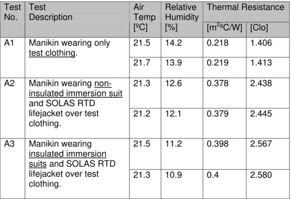
The thermal resistance results measured in air are summarized in Table 3. The results showed that the thermal resistance values obtained were repeatable, with variation in the range of 0.5%.
Thermal Resistance Test No. Test Description Air Temp [ºC] Relative Humidity [%] [m2ºC/W] [Clo] 21.5 14.2 0.218 1.406 A1 Manikin wearing only
test clothing.
21.7 13.9 0.219 1.413 21.3 12.6 0.378 2.438 A2 Manikin wearing
non-insulated immersion suit and SOLAS RTD
lifejacket over test clothing.
21.2 12.1 0.379 2.445
21.5 11.2 0.398 2.567 A3 Manikin wearing
insulated immersion suits and SOLAS RTD lifejacket over test clothing.
21.3 10.9 0.4 2.580
Table 3. Thermal Resistance Measured in Air
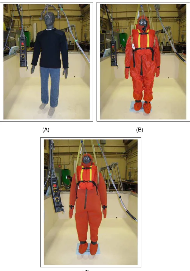
The thermal resistance tests measured in air are shown in Figure 8. In Test A1, the manikin was supported from its hanging bracket at the head. In Tests A2 and A3, the manikin was supported at the arms by slings, so the hood of the suits could cover the manikin’s head.
(A) (B)
(C)
Figure 8. Thermal Resistance Measured in Air – (A) Manikin in Test Clothing (B) Manikin in Non-Insulated Suit and (C) Manikin in Insulated Suit
The thermal resistance tests in water are shown in Figure 9. (A)
(B)
The thermal resistance results measured in water for non-insulated and insulated suits are summarized in Table 4 and Table 5 respectively. Tests WN1 and WN2 in Table 4, and Tests WI1 and WI2 in Table 5 were non-uniform cooling
conditions, where the water temperature and air temperature were very different. Test WN3 in Table 4 and Test WI3 in Table 5 were approximate uniform cooling conditions, where the water and air temperature were roughly the same, within 2 ºC. Thermal Resistance Test No. Test Description Air Temp [ºC] Water Temp [ºC] Relative Humidity [%] [m2ºC/W] [Clo] 21.31 14.0 18.2 0.104 0.671 WN1 Manikin temperature
probes in water. Air and water temperatures very different (non-uniform cooling). 22.21 14.2 18.3 0.101 0.651 20.4 14.3 18.2 0.085 0.548 WN2 One manikin temperature probe in water, another in air. Air and water
temperatures very different (non-uniform cooling). 20.4 14.6 18.3 0.085 0.548 21.71 19.7 28.3 0.082 0.529 WN3 Manikin temperature
probes in water. Air and water
temperatures roughly the same (uniform cooling).
21.91 19.8 18.3 0.083 0.535
Table 4. Thermal Resistance Measured in Water - Manikin wearing non-insulated immersion suit and SOLAS RTD lifejacket over test clothing.
Ideally, for non-uniform cooling conditions, one should account for the portion of each zone exposed to air or water, and compute the thermal resistance value accordingly using the appropriate temperature gradient. Also, inter-zone heat transfer needs to be minimized. Since it is not possible in the current test to determine the areas of each zone exposed to air and water accurately and there
1
Air temperature recorded by a handheld electronic thermometer (Omega engineering, Model HH311 Handheld Temperature and Humidity Meter, USA (Temperature measurement accuracy is ±0.7 ºC and relative humidity measurement accuracy is 2.5%) ).
is no mechanism to restrict inter-zone heat transfer in NEMO’s design, we approximated uniform cooling by conducting the tests when air and water temperature were approximately the same. The thermal resistance for non-insulated immersion suit and non-insulated immersion suit were 0.532 clo and 1.355 clo respectively (from tests WN3 and WI3).
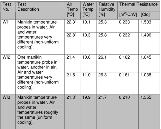
Thermal Resistance Test No. Test Description Air Temp [ºC] Water Temp [ºC] Relative Humidity [%] [m2ºC/W] [Clo] 22.31 10.1 25.3 0.233 1.503 WI1 Manikin temperature
probes in water. Air and water temperatures very different (non-uniform cooling). 22.81 10.3 25.8 0.232 1.496 21.4 10.6 26.1 0.162 1.045 WI2 One manikin
temperature probe in water, another in air. Air and water
temperatures very different (non-uniform cooling).
21.5 11.0 26.3 0.161 1.038
WI3 Manikin temperature probes in water. Air and water
temperatures roughly the same (uniform cooling).
21.31 19.9 21.7 0.210 1.355
Table 5. Thermal Resistance Measured in Water - Manikin wearing insulated immersion suit and SOLAS RTD lifejacket over test clothing.
While the water temperature warmed up slowly to air temperature, we also conducted tests to assess the variability in thermal resistance under non-uniform cooling conditions. In WN1 and WI1 cases, both manikin temperature probes were placed in water. Tamb in Equation 1 was the average water temperature
measured. In WN2 and WI2 cases, one manikin temperature probe was in air while the other was in water. T in Equation 1 was the average water and air
relative humidity. The manikin flotation postures were not changed in the frame between tests. So, the only explanation for differences in thermal resistance is the Tamb used. As expected, if Tamb is the average of water and air temperatures,
thermal resistance was lower than if water temperature was used as Tamb. As can
be seen, the thermal resistance of both non-uniform cooling cases can differ significantly from the uniform cooling case depending on how the ambient temperature was measured, inter-zone heat transfer etc. This can cause
complication when manikin results are cross-compared among laboratories. The maximum difference in thermal resistance measured between uniform and non-uniform cooling is 25% for non-insulated suit and 23% for insulated suit.
There was no leak in the insulated suit. However, there was leak in the non-insulated suit. The non-non-insulated suit was repaired prior to the experiment but there was still leak during the experiment. It was unclear where the leak occurred. It was estimated that there was 0.285 kg of water in the suit by weighting the suit before and after the experiment.
The results also showed that the thermal resistance values obtained were
repeatable, with variation typically in the range of 1% within a test condition. The largest variation was 3%.
7.0 CONCLUSIONS AND RECOMMENDATIONS
Under uniform cooling conditions, constant temperature control mode of thermal manikins and the parallel method can be used to determine thermal resistance. Under non-uniform cooling conditions, further research and development needs to be conducted before thermal manikins could be used with confidence for suit evaluation.
A leak in the non-insulated suit complicated the determination of the true thermal resistance.
To provide scientific evidence that manikin can be used as an evaluation tool for immersion suits, it is also important to assess the thermal resistance of humans and manikins in the same environmental conditions concurrently in the same laboratory.
Round Robin test protocol of thermal protective test for immersion suits (5th version) 2007/12/6
1. The purpose of the RR test
Phase one: To compare the results of three manikins
Phase two: Evaluation of the correlation between manikin and human subject 2. Perticipating test house
Research Institute of Marine Engineering Cord Group
Hohenstein
National Research Council - Institute for Ocean Technology SINTEF
3. Test specimen (Immersion suits) and size 3.1 Insulated immersion suits
3.2 Non-insulated immersion suits
Suits size: Universal size for three manikins and also universal size for human subjects Test specimens have been prepared and distributed by Viking.
4. Standard test clothing
Based on ISO 15027-3 paragraph 3.8.1.2 for both insulated and non-insulated suits and they have been already distributed by Viking.
a) cotton underwear (short-sleeved, short-legged) b) long-sleeved heavy cotton shirt
c) cotton trousers
d) woollen socks, calf length e) woollen long sleeved pullover 5. Schedule of the RR test
After the test protocol is agreed within the members, the manikin test will be conducted as soon as possible.
6. Test procedure for thermal manikin test
6.1 Donning of clothing and immersion suits
a. Weigh the mass of immersion suit and test clothing before the test in dry and after the test.
b. Manikin is to be worn only test clothing and clo is to be measured in air.
c. Manikin is to be worn immersion suits over test clothing and clo is to be measured in air.
6.2 Water temperature and air temperature
The manikin test may be conducted in either water and air temperature of between 0ºC and +2ºC for insulated suits and +5ºC for non-insulated suits, or sufficient low
temperature to measure thermal resistance of immersion suits. The water temperature should be measured at a place of at least [100mm] apart from the manikin.
6.3 Floating position (Option A)
Similar position as human subject:
Floating position of human subject wearing immersion suits and SOLAS RTD life jacket need to be measured before the manikin test.
[Half lower side of forearms and hands of manikin should be placed in the water.] 6.4 Water inside the suits (Option A)
None (Dry)
6.5 Trapped air in suits
Trapped air in suits should be purged with immersing the manikin in water to the top of shoulder before the manikin test.
6.6 Calm circulating water
Method of circulating water and approximate circulating speed shall be reported. 6.7 Measurement and record items
To obtain heat resistance, surface temperature of the manikin, outside surrounding fluid temperature (water and air) and heat generation from manikin will be necessary to be measured in the appropriate way for each manikin.
The manikin may be operated with all segments at the same surface temperature, or with constant heat generation per unit area for each segment.
6.8 Test procedure and control method of manikin
Test procedure and control method of manikin should be reported. 6.9 Test report and record
7. Test procedure for human test (basically same as ISO 15027-3)
7.1 Test subjects
Test subjects shall be volunteers and shall have signed an informed consent.
Due to the nature of this test, different test subjects to those used in the other tests can be required. Each subject shall be familiarised with the test procedure, medically screened, and their fat content shall be measured prior to the start of the test. Each subject shall be between 1 600 mm and 1 900 mm tall and shall not be more than 10 % overweight or underweight for his height and physical type as determined by a physician or physiologist or from published physiological data. Each subject shall have had a normal night's sleep before the test, a well balanced meal 1 h to 5 h before the test, and no alcoholic beverages for 24 h prior to the test. In addition to the suit system, each subject shall wear the test clothing described in 4.
The testing laboratory has to take care of the safety of the test subjects by medical check-up, monitoring and reporting the test by a physician. The preparation, the test and the follow-up have to be supervised by a physician experienced with the medical treatment of hypothermia. For the preparation of the tests ISO 9886, ISO 10551 and ISO/DIS
12894:1997 should be considered. 7.2 Principles
NOTE: The testing of immersion suits using test subjects is based on sound and proven procedures used for tests under SOLAS rules. The procedures are comparable and the results can be used vice versa. This will reduce the amount of tests for the benefit of users, manufacturers and test subjects.
The test of EN ISO 15027 class A will correspond with an insulated SOLAS suit, whereas class D will be comparable to an uninsulated SOLAS suit. The ISO classes B and C will fit in-between.
As an upgrade to SOLAS procedures, the amount of temperature transducers will be improved to at least 10 spots on skin and the measurement of the rectal temperature, see Figure 3.
The test shall be conducted in calm but circulated water with a temperature as specified by the different procedures.
The air temperature shall be < 10 °C. Each test subject will be fitted with specified amount of temperature transducers placed at the following spots as shown in Figure 3. The transducers shall be capable of measuring the surface temperature (accuracy 0,2 °C). Figure 3 - Position of measuring sites
Mean skin temperature (MST) shall be calculated according to Figure 3
MST = (0,07 * S1 + 0,175 * S3 + 0,175 * S4 + 0,07 * S5 + 0,07 * S6 + 0,05 * S7 + 0,19 * S10 + 0,2 * S13).
Mean Body Temperature (MBT) will be calculated as: MBT = (0,5 * TR + 0,5 * MST)
7.3 Procedure 7.3.1 General
Following the placement of the transducers on the body, the test subjects shall don a suit system and be dressed with all primary and secondary closures secured. The test subjects shall enter the still water and assume a relaxed position.
Suit system insulation for the conditions shall be determined when the MST becomes stable (MST shall not change by more than 0,5 °C for a period not less than 15 min). The test shall be stopped if the test subject's core temperature has fallen more than 2 °C and/or the skin temperature has reached 10 °C at any of the transducers for more than 15 min.
7.3.2 Trapped air in suits
Trapped air in suits should be purged with immersing the test subject in water to the top of shoulder before the test.
7.3.3 Class A suit system (insulated immersion suits)
Six test subjects as specified shall be exposed for a time of 6 h to water with a temperature < 2 °C.
7.3.4 Class D suit system (non-insulated immersion suits)
Six test subjects as specified shall be exposed for a time of 1 h to water with a temperature < 5 °C.