Autonomous Navigation with Mobile Robot Using
ARCHIVES
Ultrasonic Rangefinders
MASSACH -IT ITUTEg
OF IECHNOLOLGYby
JUN
24
2015
Joseph Campion
LIBRARIES
Submitted to the Department of Mechanical Engineering
in partial fulfillment of the requirements for the degree of
Bachelor of Science in Mechanical Engineering
at the
MASSACHUSETTS INSTITUTE OF TECHNOLOGY
June 2015
Massachusetts Institute of Technology 2015. All rights reserved.
Signature redacted
A uthor ...
...
Departmen of Mechanical Engineering
May 22, 2015
Signature redacted
Certified by.
...
Dr. Harrison H. Chin
Instructor/Lecturer
Thesis Supervisor
Signature redacted
A ccepted by ...
Dr. Anette Hosoi
Professor of Mechanical Engineering
Autonomous Navigation with Mobile Robot Using
Ultrasonic Rangefinders
by
Joseph Campion
Submitted to the Department of Mechanical Engineering on May 22, 2015, in partial fulfillment of the
requirements for the degree of
Bachelor of Science in Mechanical Engineering
Abstract
In this thesis, I designed and implemented an autonomous navigation system for a four-wheeled mobile robot with ultrasonic sonar sensors and a National Instruments myRIO real-time controller. LabVIEW code was developed to control the motors with PWM signals based on sensor feedback. A low-pass filter was used to improve the signal to noise ratio since the signals from the ultrasonic sonar sensors were quite noisy. Finally, I developed two basic algorithms to maneuver the mobile robot: the first algorithm uses proportional control to maintain a specific distance from a target in front of the mobile robot; the second also uses proportional control to keep the robot at a specified distance away from a wall to its side as it travels forward. Thesis Supervisor: Dr. Harrison H. Chin
Acknowledgments
The author would like to acknowledge his supervisor, Dr. Harrison Chin, for all his patience and guidance. The author would also like to acknowledge Brandy Baker for her never-ending support and optimism. Finally, the author would like to thank Joanne Zhou for being the best friend possible during the toughest of times.
Contents
1 Introduction 2 Hardware 2.1 Overview. . . . . 2.2 Sonar Sensors . . . . 2.3 Pulse-Width Modulation 3 Software 3.1 Overview. . . . . 3.2 Motor Control. . . . . . 3.3 Low-Pass Filter . . . . . 3.4 Proportional Control . . 4 Results 4.1 Step Response. . . . . 5 Conclusion 5.1 Future W ork. . . . . A LabVIEW Code 13 15 15 16 17 19 19 20 20 22 23 23 25 25 27 . . . . . . . . . . . . . . . . . . . . . . . . . . . .List of Figures
1-1 Tesla's Model S which includes Auto Pilot features for hands free
high-w ay driving . . . . 13
2-1 View of the set up of the mobile robot. All the components, including the myRIO and sonar sensors, are securely fastened on the structure. 15 2-2 MaxBotix MB1030 LV-MaxSonar-EZ3 High Performance Ultrasonic Rangefinder. . . . . 16
2-3 Graph of PWM control signal. The dashed line shows the mean value seen by the receiver of the signal. . . . . 17
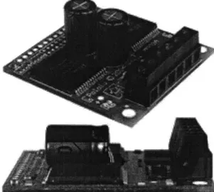
2-4 Pololu Dual Motor Driver Carrier MD03A. . . . . 18
3-1 User interface of wall following LabVIEW code that can change and plot relevant variables such as the gain constant of the controller and distance to target in real time. . . . . 19
3-2 Pololu Dual Motor Driver Carrier MD03A connections. . . . . 20
3-3 Bode plot of lowpass filter (gain only). . . . . 21
3-4 Effect of low-pass filter on noisy signal. . . . . 21
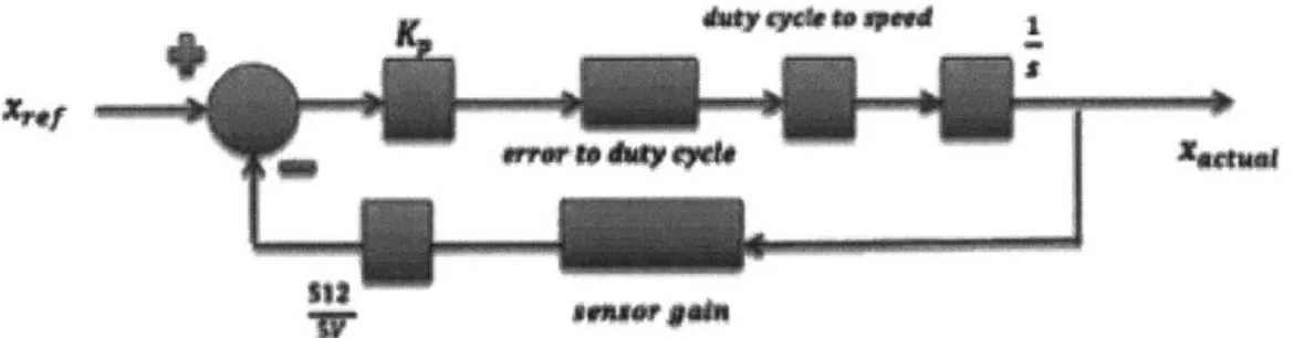
3-5 Closed-loop control loop of system. . . . . 22
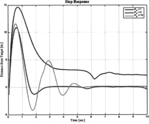
4-1 Step Response of mobile robot for various Kp. . . . . 24
5-1 Google's self-driving car. . . . . 26
Chapter 1
Introduction
Autonomous navigation has been a challenging problem in robotics for the past few decades. However, the vast range of applications for autonomy in vehicles and other systems has made it a worthwhile problem in many fields. For example, the auto-mobile industry is beginning to explore self-driving technologies in order to improve vehicle safety. Given that 1.3 million people die annually around the globe due to traf-fic accidents, Sebastion Thrun, founder of Google X and the Driverless Car Project, has made it one of his life goals to make automobiles autonomous. Companies such as Tesla share this desire as evidenced by their Model Ss Autopilot feature that allows the car to stay in a lane automatically, change lanes with the tap of a button, and read road to manage speed.
Teslas Auto Pilot feature takes advantage of an array of sensors and sensor fusion to localize traffic for the car to avoid obstacles on the road. Specifically, the most recent Model S utilizes radar sensors, a camera, ultrasonic rangefinders, and GPS in unison to navigate the vehicle. This thesis is a platform for the author to become more familiar with autonomous navigation in robotic vehicles. Since the robot in this thesis is much smaller in size and scope than the Model S, it will only be using ultrasonic sonar sensors to detect surrounding objects. As an engineer passionate about exciting possibilities such as being driven to work someday by a self-driving car and also contributing to the prevention of innumerable future traffic accidents, I hope to use this thesis to springboard into more advanced research in this area.
Chapter
2
Hardware
2.1
Overview
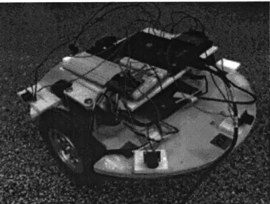
Figure 2-1: View of the set up of the mobile robot. All the components, including the myRIO and sonar sensors, are securely fastened on the structure.
The mobile robot is approximately 15 in diameter (given its circular shape) and approximately 8 tall and its peak height. The two motor-driven wheels are located on the sides and two castor wheels are located underneath the mobile robot in the front and rear for stability. The NI myRIO sits on top of the mobile robot. It is connected
the myRIO while the ultrasonic rangefinders are all attached to the protoboard on Connector A. In the back of the robot is a 12V 2000mAH Tenergy battery pack that is connected to the GND and power inouts of the Pololu carrier as well as to the myRIO through a barrel connector. Four MaxBotix rangefinders are positioned along the outer edge of the robot. Two of the rangefinders are used in this thesis: the front most rangefinder that faces forward and the upper right rangefinder that is positioned to face a 30 angle from the axes of the wheel. To collect data, a USB extension cord was connected to the myRIO so that LabVIEW could trace the inputs and outputs in real-time.
2.2
Sonar Sensors
Figure 2-2: MaxBotix MB1030 LV-MaxSonar-EZ3 High Performance Ultrasonic
Rangefinder.
Sonar is a commonly used sensing capability in the robotics research community. While many in this field believe sonar is unreliable, other experts believe that its bad reputation is undeserved. Sonar is an acronym for SOund Navigation And Ranging. It is a technique that uses sound wave propagation to detect objects, typically in underwater scenarios. In this case, the term sonar will be used for airborne ultrasonic range sensing. Range measurements can be determined by the time of flight (TOF) of the ultrasonic pulse. In cases where a single transducer acts as both the emitter and receiver of the pulse, the range is calculated by multiplying the speed of sound in air by the time of flight and dividing by 2 account for the pulse traveling to and
from the target. The speed of sound at average room temperature (22.5C) is 345 m/s. Therefore the range will be 174 multiplied by the time of flight.
2.3
Pulse-Width Modulation
Controlsignal,
u On U (Mean V~alue) Off 0 - - - -Duty cycle, D LJ PNriod, T, -100%Figure 2-3: Graph of PWM control signal. The dashed line shows the mean value seen by the receiver of the signal.
Pulse-width modulation, or PWM, is a technique used to encode information into a pulsing signal. The signal in question has two values, either ON or OFF (or HIGH or LOW), and the message is determined by the relationship between the time spent in the HIGH position versus time spent in the LOW position. The term duty cycle is used to express this ratio, and it is the proportion of ON time to the regular period
interval. Duty cycle is expressed as a percent, where 100 % is considered always ON.
While PWM can be used to encode information, its main function is to control power to electronic devices such as a DC motor. Instead of controlling the voltage delivered to a motor by an analog voltage, a PWM signal is used to control the voltage. At high enough frequencies, the power delivered to the motor is by the PWM signal is a result of the average total voltage. Therefore, the higher the time spent in the
the motor sees and therefore sets the power delivered to the motor.
A Pololu Dual VNH3SP30 Motor Driver Carrier MD30A was used to move the
robot. The carrier and NI myRIO were powered by a 12V Tenergy 2000mAH NiMH battery pack. The PWM signal from the myRIO was delivered to the 1PWM and 2PWM for the right and left motors of the robot respectively. While the nominal 5V signal was delivered to the A input to move the robot forward or delivered to the B input to move the robot in reverse. The PWM signal from the NI myRIG is delivered to the X input of the Polulu driver to regulate the speed of the motor.
Figure 2-4: Pololu Dual Motor Driver Carrier MD03A.
Chapter 3
Software
3.1
Overview
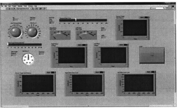
Figure 3-1: User interface of wall following LabVIEW code that can change and plot relevant variables such as the gain constant of the controller and distance to target in real time.
The ultrasonic rangefinders deliver the analog voltage to the myRIO through the
into distance in inches and compared to the reference or desired input distance. The resulting error term is then multiplied by a gain factor and used to determine the duty cycle of the motors.
3.2
Motor Control
4K .
OUT 1A
mouris
IC .-.
OUT
I1a
GMVIN()
200e
OUT 2A
A
e
OUT:28
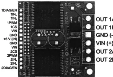
Figure 3-2: Pololu Dual Motor Driver Carrier MD03A connections.
A PWM signal with variable peak voltage was created in LabVIEW using a
built-in square wave function. The square wave was tuned to the desired frequency with a controlled input. When the square wave is greater than zero, in the HIGH mode, the analog output voltage is set to the desired voltage. When the square wave is less than zero, in the LOW mode, the analog output voltage is set to zero. The resulting signal of the analog output is a PWM signal with the proper duty cycle and voltage necessary to move the motor at the desired speed.
3.3
Low-Pass Filter
A low-pass filter is a filter that passes signals with frequencies below a certain
cut-off frequency and attenuates signals with frequencies above the cut-cut-off frequency. This design eliminates certain unwanted or noisy frequencies that are higher than
0
20
dB~
0.1
1 10100
DifmwiOulesa mrqueany
Figure 3-3: Bode plot of lowpass filter (gain only).
the desired one. The effect of a low-pass filter can best be gleaned from a bode plot of the filter transfer function. At low frequencies, below the cut-off frequency, the gain of the transfer function is unison, which allows wanted signals to pass relatively unchanged. Above the cut-off frequency however, the gain drops significantly, which attenuates or lessens their value. For this thesis, the purpose of the low-pass filter is to eradicate the noise related with the analog ultrasonic sonar signal received from the transducer. IU ) 13
I.
Mop ~5 ~I * d# ~of the emitter is 20Hz. However, given the relatively low speed of the robot and the fact that there are very few edges where the distance from the sensor will change drastically, it is safe to assume the distance senses should not change drastically every 0.5s. Therefore, if we use a low-pass filter with a cut-off frequency of 2Hz, random noisy measurements at the 20Hz level should be attenuated by an order of magnitude.
3.4
Proportional Control
Xr~f
Figure 3-5: Closed-loop control loop of system.
The method used to help the robot move autonomously is a proportional controller that allows the robot to maintain a certain distance from an object in front of the robot. Teslas Auto Pilot feature can adjust the distance between the car and the car directly in front of it. In a similar fashion, this modality can maintain a constant position away from a target using proportional control. After the signal from the sonar sensor is filtered, it is converted into a distance in inches according the equation above in LabVIEW. Then the distance is compared to a reference, or desired, set-pointsignal: the target distance. The resulting difference is the error. The error is then multiplied by a proportional gain constant. This term is then used to determine the duty cycle of the motors. A negative error, which occurs when the robot is too far in front of the target distance will move the mobile robot backward while a positive error will move the mobile robot forward.
Chapter 4
Results
The mobile was placed at a set position approximately 30 in front of wall and then turned on. The target distance was set to 20 so the robot moved forward until it remained steady at the target distance away from the wall. The experiment was repeated for three different values of Kp. By turning on the mobile robot at a set distance away from the target distance, the resulting movement is essentially a step response.
4.1
Step Response
The step response with Kp = 1 had a large steady state error. It did not settle at the
target distance. Also, the response was very slow; the time constant was large and it
took a considerable amount of time to reach the steady state. For Kp = 1 there was
a large overshoot. If the purpose of this autonomous navigation system is to avoid crashing into other vehicles, a large overshoot is undesirable because it could lead to
potential crashes. For Kp = 5 the response was timely and had a very low overshoot.
__________ Step tepe
is
aFi
u 4 SR o m r f i
Figure 4-1: Step Response of mobile robot for various Kp.
Chapter 5
Conclusion
Proportional control for the DC motors was sufficient enough to maneuver the robot to a desired position with minimal error. Albeit somewhat noisy, the sonar sensors were able to determine position well enough for the robot to settle upon a specified
position. A proportional controller with a gain constant of Kp = 5 was optimal for
the design of a mobile robot that can stay at a certain position behind an object without hitting it. The low-pass filter helped to remove and sudden jumps in the input signal from possibly deflected sonar pings.
5.1
Future Work
There are many possible projects for future iterations of this robot. For example, integrating multiple sensors for improved objection would be worthwhile. Fusing different types of sensors, such as infrared or camera vision, would be interesting and could possibly eliminate the inaccuracy due to the sonar sensors alone. The sonar sensors in this design were set to analog; however, it is possible to use digital and serial inputs from these specific sensors, which could be much less noisy. Furthermore, implementing PI and PID control would be much more sufficient in trying to eliminate the error in position of the robot. LabVIEW offers many internal PID controllers that
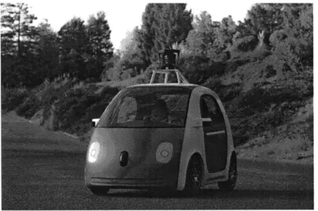
Figure 5-1: Google's self-driving car.
This feature would be similar to the Auto Pilot system on the Tesla Model S that is mentioned in the Introduction.
Appendix A
LabVIEW Code
Figure A-1: LabVIEW code for position controller.
IE-n f, 'K ... ... ... ... ... .