Publisher’s version / Version de l'éditeur:
Proceedings of the 2009 International Thermal Spray Conference and Exposition,
p. 97, 2009-05-04
READ THESE TERMS AND CONDITIONS CAREFULLY BEFORE USING THIS WEBSITE. https://nrc-publications.canada.ca/eng/copyright
Vous avez des questions? Nous pouvons vous aider. Pour communiquer directement avec un auteur, consultez la
première page de la revue dans laquelle son article a été publié afin de trouver ses coordonnées. Si vous n’arrivez pas à les repérer, communiquez avec nous à PublicationsArchive-ArchivesPublications@nrc-cnrc.gc.ca.
Questions? Contact the NRC Publications Archive team at
PublicationsArchive-ArchivesPublications@nrc-cnrc.gc.ca. If you wish to email the authors directly, please see the first page of the publication for their contact information.
NRC Publications Archive
Archives des publications du CNRC
This publication could be one of several versions: author’s original, accepted manuscript or the publisher’s version. / La version de cette publication peut être l’une des suivantes : la version prépublication de l’auteur, la version acceptée du manuscrit ou la version de l’éditeur.
Access and use of this website and the material on it are subject to the Terms and Conditions set forth at
Mullite Coatings Produced by APS and SPS: Effect of Powder
Morphology and Spray Processing on the Microstructure, Crystallinity
and Mechanical Properties
Wang, Y.; Lima, R. S.; Moreau, C.; Garcia, E.; Guimaraes, J.; Miranzo, P.;
Osendi, M. I.
https://publications-cnrc.canada.ca/fra/droits
L’accès à ce site Web et l’utilisation de son contenu sont assujettis aux conditions présentées dans le site LISEZ CES CONDITIONS ATTENTIVEMENT AVANT D’UTILISER CE SITE WEB.
NRC Publications Record / Notice d'Archives des publications de CNRC:
https://nrc-publications.canada.ca/eng/view/object/?id=9618ce6c-f1ed-439b-931a-9a460e1cb000 https://publications-cnrc.canada.ca/fra/voir/objet/?id=9618ce6c-f1ed-439b-931a-9a460e1cb000
Mullite Coatings Produced by APS and SPS: Effect of Powder Morphology and
Spray Processing on the Microstructure, Crystallinity and Mechanical Properties
Y. Wang,* R. S. Lima, C. Moreau
National Research Council of Canada, Boucherville, QC, Canada *E-mail: youliang.wang@cnrc-nrc.gc.ca
E. Garcia, J. Guimaraes, P. Miranzo, M. I. Osendi
Consejo Superior de Investigaciones Científicas (CSIC), Instituto de Ceramica Y Vidrio (ICV), Madrid, Spain
Abstract
Mullite coatings are being considered as one of the main protective layers of environment barrier coatings (EBCs) to be used to protect Si-based substrates for the next generation of gas turbine engines. In this study, the influence of the powder morphology and processing conditions on the microstructure (SEM), relative crystallinity (XRD) and mechanical properties (hardness and elastic modulus) of mullite coatings was investigated. To accomplish this objective, coatings produced from three types of mullite powders, fused and crushed, spray-dried and spray-spray-dried flame-spheroidized were deposited by conventional air plasma spray (APS). In addition, mullite suspensions were deposited via suspension plasma spray (SPS). The particle state (temperature and velocity values) for all these systems were measured and related to the effects of powder morphology and spray processing conditions with the overall coating characteristics as an attempt to create a process map for engineering mullite coatings for EBC applications. Coating crystallinity, microstructures and mechanical properties can be changed considerably according to powder morphology, processing and in-flight particle characteristics.
Introduction
Various single layer and multilayer environment barrier coatings (EBCs) have been developed to protect Si-containing components from corrosive water containing environment and high temperature. Mullite (Al2O3-72-77wt%SiO2) coatings are being considered as one of the main protective layers of EBCs for the next generation of gas turbine engines because of its low density, low thermal conductivity, stability in oxidizing environment, and low thermal coefficient of expansion similar to that of Si-based ceramic component (Ref 1). Thermal spray is the most used technique to deposit EBCs on different components (Ref 2). However, plasma sprayed mullite coatings tended to crack and debond during thermal cycling (Ref 3-5). It was identified that crystallization of amorphous
mullite during thermal cycling with the associated volumetric shrinkage was the primary mechanism for the cracking and debonding of the thermal sprayed mullite coatings (Ref 5-7). In addition, alumina and silica-rich second phases, both impurities in the powder and new phases generated during the thermal spray, can cause cracking or debonding of the coatings because of the differences in physical and mechanical properties between mullite and alumina or silica (Ref 5-7). Different efforts have been made to reduce the amorphous phase in the as-deposited coatings or avoid the generation of second phases during the thermal spray process. It is found that substrate temperatures during thermal spray exhibit a significant effect on the phase composition, microstructure and mechanical integrity of thermal sprayed mullite coatings. Fully crystalline mullite coatings were obtained by heating the substrate above the crystallization temperature (∼1000o
C) in a furnace during the thermal spray (Ref 5).
Although different thermal spray conditions have been tried in order to produce highly crystalline mullite coatings, few studies have been done on the effect of feedstock morphology on the microstructural characteristics and properties of mullite coating. In this study, the influence of the powder morphology and processing conditions on the microstructure (FE-SEM), relative crystallinity (XRD) and mechanical properties (hardness and elastic modulus) of mullite coatings was investigated. Coatings produced from two types of mullite powders (spray-dried and spray-dried and flame-spheroidized) were deposited by conventional air plasma spray (APS) and mullite suspension coatings were deposited via suspension plasma spray (SPS). The particle state (temperature and velocity values) for all these systems were measured and related to the effects of powder morphology and spray processing conditions with the overall coating characteristics in order to create a process map for mullite coatings.
Experimental Procedure
Coating Deposition
In conventional APS, a torch with three converging plasma jets and an axial feed injection port (Axial III, Northwest Mettech, North Vancouver, BC, Canada) was used to deposit coatings by using commercial and experimental conventional powders of different morphologies and particle size distributions. The commercial powder was fused and crushed (FC) (Saint-Gobain #1020 mullite, Saint-Gobain Ceramics & Plastics, Inc. Worcester, MA, USA). The experimental powders were: (i) spray-dried and flame-spheroidized large particle cut (SD+FS-L), (ii) spray-dried and flame-spheroidized small particle cut (SD+FS-S) and (iv) and spray-dried (SD). Particle size distributions were measured with a Coulter LS Particle size analyzer (Beckman Coulter LS 13320, Beckman Coulter, Miami, FL, USA). The in-flight particle state (particle velocity and temperature) was measured by a commercially available diagnostic system DPV-2000 (Tecnar Automation, St-Bruno, QC, Canada).
The same plasma torch was used for SPS with a suspension of 5wt.% solids in a mixture of 30wt.% ethylene glycol and ethanol. The suspension was injected into the plasma jet by a suspension feeder (Model 640, Northwest Mettech, North Vancouver, BC, Canada). The powder used for the suspension is a commercial MP40 (Chichibu MP40, Scimarec Co. Ltd., Tokyo, Japan). The temperature and velocity of in-flight particles in suspension plasma spray were measured with a commercial diagnostic system AccuraSpray® G2 (Tecnar, St-Bruno, QC, Canada).
For conventional APS and SPS, the temperature of the coatings during spraying was monitored by using a pyrometer (8-14 µm wavelength range). Coatings were deposited on low carbon steel substrates. The substrates were grit-blasted with 24 grit Al2O3 (600-850 µm) particles prior to deposition. Coating Characterization
The coating microstructures were observed by field-emission scanning electron microscope (FE-SEM) (S4700, Hitachi, Tokyo, Japan). The samples were prepared by standard metallographic methods. A Brucker D8-Discovery diffractometer (Brucker AXS Inc. Madison, WI, USA) was used to analyze the phase composition of the coatings. As an attempt to compare the degree of crystallinity among the coatings, the ratio of peak areas between 20 and 40° to the total integrated area in this region, including the amorphous hump, was measured and defined as crystallinity index (CI). Vickers microhardness (HV) was measured under a 2.8-9.8 N load on the polished cross-sections of the coatings by using an instrumented indentation tester ZHU 2.5 (Zwick GmbH & Co. KG, Germany). Elastic modulus was calculated by the equipment software using the unload part of the load/displacement curve in the elastic regime.
Each powder was sprayed using two sets of spray parameters to induce distinct particle temperature and velocity levels and a total of 10 coatings were deposited by conventional APS and SPS. The input power (P), temperature (T) and velocity (V) of in-flight particles, the thickness increase per pass (µm/p), crystallinity index (CI), hardness (HV) and elastic modulus (E) of the as-sprayed coatings were listed in Table 1.
Results and Discussion
Feedstock Powders
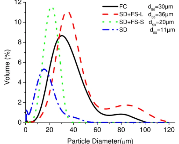
Figure 1 shows the particle size distribution of the powders used for the conventional APS. The FC and SD+FS-L powders exhibit the largest particles and widest particle distribution. The SD and SD+FS-S powder exhibit the narrowest size distribution the smallest particles. The d10, d50 and d90 values of the MP40 powder for suspension plasma spray were 1.1, 1.8 and 2.8 µm, respectively. XRD spectra of the powders indicate that the crystallinity indexes of all the powders are close to unite, indicating that the powders used are well crystallized.
0 20 40 60 80 100 120 0 2 4 6 8 10 12 Vol u me (% ) Particle Diameter(μm) FC d 50=30µm SD+FS-L d 50=36µm SD+FS-S d 50=20µm SD d50=11µm
Figure 1: Particle size distributions of the powders used in conventional plasma spray.
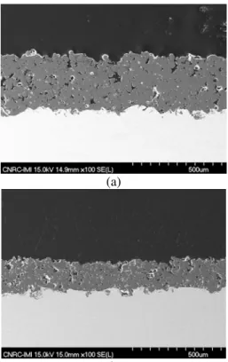
Coatings Produced from Fused and Crushed (FC) Powder The main characteristics of the FC1 and FC2 coatings can be found in Table 1. By looking at the microstructures of both coatings (Fig. 2) it is evident that the FC1 coating is denser. As illustrated by Fig. 2a, the individual splats in FC1 can not be easily discerned and the pores are smaller than those of the FC2 coating (Fig. 2b). These microstructural characteristics agree with the data shown in Table 1, i.e., FC1 particles were sprayed at higher temperature and velocity values than those of FC2. The coating/substrate temperatures for deposition of coatings FC1 and FC2 were, respectively, ∼290o
C and ∼190o
C. As crystallization temperature of mullite is approximately 1000oC, the crystallization of amorphous mullite on the substrate was not significant.
Table 1: Input power, in-flight particle state, deposition rate and coating’s properties.
n.a. – not available
(a)
(b)
Figure 2: SEM micrographs of the polished cross sections of (a) FC1 and (b) FC2 coatings.
The higher values of CI of the FC1 coating when compared to that FC2 (56 % and 49%) in Table 1 implies that the percentage of fully molten particles for the FC2 coating in the plasma jet was higher than that of FC1. As the particle velocity for deposition of FC2 coating is about half that of FC1 (Table 1) it is logical to assume that the longest dwell
time of the FC2 particles in the plasma jet contributed significantly for their higher degree of melting.
Coatings Produced from Spray-Dried and Flame Spheroidized Large Size (SD+FS-L) Particle Powder
The SD+FS-L1 and SD+FS-L2 coatings were deposited using similar values of particle temperature and velocity (Table 1). The microstructures and the crystallinity indexes of the two coatings are also similar as indicated by Fig. 3 and Table 1.
(a)
(b)
Figure 3: SEM micrographs of the polished cross sections of (a) SD+FS-L1 and (b) SD+FS-L2 coatings.
Since the spray dried and flame spheroidized, and FC powders were melted during the synthesizing processes, they should exhibit similar particle densities. Considering that the FC and SD+FS-L powders exhibit almost the same size distributions (Fig. 1), it is an interesting opportunity to verify any possible advantage regarding the two powder production methods, i.e., (i) fusing and crushing versus (ii) spray-drying and flame-spheroidizing on the properties of mullite coatings.
The FC1, FC2, SD+FS-L1 and SD+FS-L2 particles were sprayed at temperature and velocity ranges of 2485-2635oC and 191-489 m/s, respectively (Table 1). Despite these differences, the CI levels of these coatings were similar (Table 1). The maximum temperatures for the SD+FS-L1 and SD+FS-L2 coatings were similar to those of the FC coatings, i.e., ∼190 and ∼290oC, respectively. Therefore, these results indicate that the coating temperature during deposition exhibits a preponderant effect on the crystallinity (CI) of the
P T V CI HV E CI/E
Coating
kW oC m/s µm/p % GPa GPa FC1 113 2635 489 14.8 56 n.a. n.a. n.a. FC2 76 2485 191 13.4 49 3.7 59 0.83 SD+FS-L1 86 2622 200 10.5 54 4.0 61 0.89 SD+FS-L2 100 2627 237 n.a. 53 4.6 72 0.74 SD+FS-S1 113 2622 566 10.3 69 4.3 83 0.83 SD+FS-S2 76 2526 199 10.1 50 3.3 59 0.85 SD1 93 2120 760 28.5 52 3.8 58 0.90 SD2 79 2220 360 26.8 45 2.4 49 0.92 SPS1 71 3240 715 7.1 64 2.0 43 1.49 SPS2 95 n.a. 723 4.5 39 4.1 64 0.61
coating for highly dense particles, independently of the powder manufacturing process.
In addition to the CI, the E values of these coatings are of extremely importance. It can be hypothesized that CI and E are among the most important coating characteristics for the application of mullite coatings as EBCs. Under “ideal conditions”, mullite coatings would be engineered to exhibit high CI and low E values, to avoid phase transformation and maximize compliance levels. Based on this hypothesis, an “arbitrary number” is proposed, the CI/E ratio (Table 1). The SD+FS-L1 coating exhibits the highest measured CI/E value for the coatings produced from highly dense particles (Table 1), which is a desirable characteristic.
Coatings Produced from Spray Dried and Flame Spheroidized Small Size (SD+FS-S) Particle Powder
As shown in Fig. 1, the SD+FS-S dense particles are smaller and exhibit a narrower distribution when compared to the FC and SD+FS-L particles. It is important to point out again that the FC and SD+FS particles are dense and probably exhibit similar density levels. According to theoretical analysis (Ref 6), smaller particles tend to exhibit larger acceleration rates and velocity levels in the plasma jet. Therefore, this theoretical analysis agrees high the higher velocity levels achieved by the SD+FS-S1 particles (566 m/s) when compared to those of the FC and SD+FS-L dense particles. It is interesting to examine the microstructures of these coatings (Fig. 4).
(a)
(b)
Figure 4: SEM micrographs of the polished cross sections of (a) SD+FS-S1 and (b) SD+FS-S2 coatings.
The coatings SD+FS-S1 and SD+FS-S2 were sprayed at similar temperature levels; however, the lowest velocity of the latter (Table 1) resulted in the production of a porous coating (Fig. 4b). In addition, it is possible to identify a considerable number of spherical particles in the microstructure of the coating SD+FS-S2 (Fig. 4b), which is a result of semi-molten impinging the substrate at low velocity levels (absence of flattening) and/or re-solidified particles that became entrapped in the coating microstructure during thermal spraying.
The microstructure of thermal spray coatings are closely related to velocity of impinging particles and their degree of melting. By looking at Table 1, it is possible to observe the link between the high particle levels of the SD+FS-S1 particles and the CI of the coating (69%), which is the highest among the FC and SD+FS particles. The maximum temperature of the SD+FS-S1 coating was ∼290o
C, which is much lower than that of the crystallization of mullite (∼1000o
C).
Therefore, in order to produce high crystalline mullite coatings, engineering powders with morphologies and particle size distributions similar to those of this power (SD+FS) and spray them at the SD+FS-S1 in-flight conditions seem to provide an important advantage. The maximum temperature of the SD+FS-S2 coating was ∼190o
C.
Coatings Produced from Spray-Dried (SD) Powder
The SD1 and SD2 coatings were sprayed by using the narrow 0.8 cm (5/16”) torch nozzle, instead of the large 1.3 cm (1/2”) nozzle used to deposit the other powders via conventional APS. In addition, the SD1 and SD2 coatings were sprayed using an Ar/H2 based plasma, whereas, the other coatings produced by conventional APS were produced by an Ar/N2 plasma mixtures. It has been demonstrated that Ar/H2 based plasmas generate particles with higher velocities and lower temperatures than those of Ar/N2 ones (Ref 9).
Therefore, higher particle velocities (up to 760 m/s) and lower temperatures attained by the SD particles (Table 1) are a direct result of the plasma gas combination and the narrow torch nozzle size. Figure 5 shows the microstructures of the SD1 and SD2 coatings. The highest deposition rates of the coatings produced in this study were obtained from spray dried powders (∼25 µm/pass - Table 1). All the observations (Fig. 5) indicate that both coatings are relatively dense. As previously stated, the SD particles were sprayed using the narrow 0.8 cm (5/16”) nozzle. When this nozzle was employed to spray the other powders (i.e., FC, SD+FS) via conventional APS, no significant coating deposition was obtained. These powder particles were bounced off by the substrates due to insufficient heating.
The SD particles are porous, exhibit lower mass and density when compared to FC and SD+FS particles. It is hypothesized that due to the larger surface area, lower mass and porous
microstructure (i.e., low thermal conductivity), SD particles are easier to be melted (at least on its outer shell) when compare to dense particles (e.g., FC and SD+FS). Therefore, the highest deposition rates have been obtained by using the SD powder (Table 1).
By looking at Figs. 5a-b, it is found that the average pore size of coating SD1 is smaller than that of SD2. It is reasonable to believe that the microstructure difference was caused by the particle velocity difference during impact onto the substrates since the particle velocity for deposition of SD2 is only a half of that of SD1 (Table 1).
It has to be stressed that the SD1 and SD2 coatings exhibited the highest CI/E ratios (0.90 and 0.92, respectively) of all coatings produced via conventional APS in this study (Table 1). Therefore, the availability of SD particles may be an important asset when engineering mullite coatings for EBC applications.
(a)
(b)
Figure 5: SEM micrographs of the polished cross sections of (a) SD1 and (b) SD2 coatings.
Coatings Produced by Suspension Plasma Spray
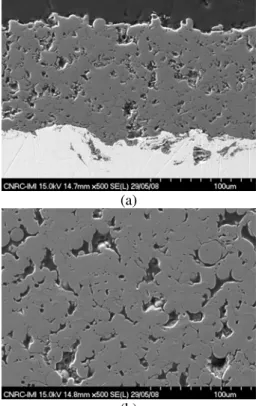
Coatings SPS1 and SPS2 (Table 1) were deposited by SPS using a commercially available powder. Figure 6a shows that the coating SPS1 was built up by irregular-shaped particles, indicating that the original individual particles were not completely melted and are distinguishable at the power input of 71 kW, as indicated in Table 1.
(a)
(b)
Figure 6: SEM micrographs of the polished cross sections of (a) SPS1 and (b) SPS2 coatings.
When the power input increased from 71 kW (SPS1) to 95 kW (SPS2), the sprayed coating SPS2 contains agglomerates of particles that were molten during thermal spraying, as highlighted by the ellipse in Fig. 6b. These observations are consistent with the XRD analysis results (Table 1). The CI of coating SPS1 is 64%, whereas, that of SPS2 is 39%. Therefore, at 95 kW, the degree of melting of the particles was increased substantially. It is generally accepted that well-molten particles arriving at the substrate at high velocity levels causes a reduction in the porosity levels of the coating. No significant amounts of agglomerates and pore features described for coating SPS2 were observed in coating SPS1. Therefore, the lower plasma powder (71 kW) employed to spray the SPS1 coating is likely the cause for the formation of these microstructural features.
It has to be highlighted that the agglomerates of the SPS2 coating (Fig. 6b) exhibit two types pores: (i) larger pores comparable to that of original particles (d10 = 1.1 µm, d50 = 1.8 µm, d90 = 2.8 µm) and (ii) fine pores much smaller than the original particles. It is hypothesised that the agglomerates observed in the SPS2 coating (Fig. 6b) may have been formed by one of two distinct processes: (i) in-flight particle agglomeration or (ii) impact particle agglomeration.
Concerning in-flight particle agglomeration, previous studies demonstrated that coatings produced from liquid precursors consist of agglomerates of small particles that exhibit two types of pores in the coating structure: (i) large pores in
between agglomerates and (ii) fine pores inside agglomerates (Ref 6, 8), just like the ones observed in Fig. 6b. Therefore, the previously molten agglomerates observed in coating SPS2 (Fig. 6b) may be formed particle collision in the plasma jet before impact onto the substrate (Ref 6, 8). The large pores in coating SPS2 may be generated by stacking defects of small agglomerates or individual larger particles that arrived at the substrate with low impact velocity and/or melting degree. On the other hand, the fine pores inside agglomerates might be produced by release of solvent or gas product during the molten state (Ref 6, 8). Concerning impact particle agglomeration, it can be hypothesised that semi and fully molten particles simply created agglomerates in the coating microstructure by impact on previously deposited layers. The irregular particles observed in the SPS2 coating microstructure (Fig. 6b) may have been entrapped in the coating microstructure by the subsequent impact of fully molten ones. Further studies on particle and splat formation will have to be carried out to test these both hypotheses. Other authors also have reported the production of mullite coating via suspensions, by high velocity oxy-fuel (HVOF) (Ref 11) and APS (Ref 12). The coatings sprayed by HVOF exhibited highly compacted microstructures, very different from those shown in Fig. 6. These types of microstructures were probably the results of the high velocities attained by the HVOF-sprayed particles (up to ∼1100 m/s). These coatings were also highly crystalline; however, a series of vertical cracks was generated during deposition (Ref 11). The suspension (sol-gel) coatings produced by APS were reported to be dense, highly crystalline and crack-free (Ref 12).
Finally, it is important to point out that the SPS1 coating exhibited the second highest CI (64%) and the highest CI/E ratio (1.49) of the coatings produced in this study (Table 1). Therefore, the mullite coatings by SPS exhibit a completely new microstructure and their performance in EBC application is worth investigating.
Conclusions
Mullite coatings produced from fused and crushed (FC), spray-dried (SD) and spray-dried and flame-spheroidized (SD+FS) powders were successfully deposited by conventional APS. Mullite coatings with complete novel microstructures were sprayed by SPS. When engineering mullite coatings for EBC applications, the particle morphology and density, particle size distribution, temperature and velocity, and processing were found to have significant effects on the microstructure, crystallinity and mechanical properties of the deposited coatings. In general, regarding conventional APS, dense particles (e.g., SD+FS) can be used to engineer highly crystalline coatings, whereas, spraying SD powders are suitable to tailor coatings that exhibit high crystallinity-to-elastic modulus ratios. Mullite coatings produced by SPS can exhibit at the same time high crystallinity levels and the highest crystallinity-to-elastic modulus ratio of all coatings produced in this study;
characteristics that are not observed for coatings deposited via conventional APS.
Acknowledgements
The authors would like to thank the assistance of Dr. J. Oberste-Berghaus in the production of the SPS coatings. The authors also would like to acknowledge the financial support of the NRC and CSIC for this project.
References
1. G. Brunauer, F. Frey, H. Boysen and H. Schneider, High Temperature Thermal Expansion of Mullite: an In-Situ Neutron Diffraction Study up to 1600°C. J. Eur. Ceram. Soc., 2001, 21, p 2563–2567
2. K.N. Lee, Current Status of Environmental Barrier Coatings for Si-Based Ceramics, Surf. Coat. Technol., 2000, 133/134, p 1-7
3. J.R. Price, M. van Roode and C. Stala, Ceramic Oxide Coated Silicon Carbide for High Temperature Corrosive Environments, Key Eng. Mater., 1992, 72-74, p 71-84 4. J.I. Federer, Alumina Base Coatings for Protection of SiC
Ceramics, J. Mater. Eng., 1990, 12(2), p 141-149
5. Kang N. Lee, Robert A. Miller, and Nathan S. Jacobson, New Generation of Plasma-Sprayed Mullite Coatings on Silicon Carbide, J. Am. Ceram. Soc., 1995, 78(3), p 705-710
6. P.H. McCluskey, H.E. Eaton Jr., D.R. Godin, G.E. Forster, H.D. Harter, S. Chin, G.A. Cotnoir, and C.A. Ellis, Plasma Sprayed Mullite Coatings on Silicon Based Ceramic Materials, U.S. Patent No. 6468648, Oct. 22, 2002
7. I.T. Spitsberg, H. Wang and R.W. Heidorn, Method for Thermally Spraying Crack-free Mullite Coatings on Ceramic-based Substrates, U.S. Patent 6296909 B1, Oct. 2, 2001
8. Y. Wang, Deposition of Solid Oxide Fuel Cell Electrodes by Solution Precursor Plasma Spray, Ph.D. Thesis, University of Toronto, Canada, 2008
9. B.R. Marple, R.S. Lima, C. Moreau, S.E. Kruger, L. Xie, and M.R. Dorfman, Yttria-Stabilized Zirconia Thermal Barriers Sprayed Using N2-H2 and Ar-H2 Plasmas: Influence of Processing and Heat Treatment on Coating Properties, J. Therm. Spray Technol., 2007, 16(5-6), p 791- 797
10. Y. Wang and T.W. Coyle, Solution Precursor Plasma Spray of Nickel-Yttria Stabilized Zirconia Anodes for Solid Oxide Fuel Cell Application, J. Therm. Spray Technol., 2007, 16(5-6), p 898- 904
11. J. Oberste Berghaus and B.R. Marple, High Velocity Oxy-Fuel (HVOF) Suspension Spraying of Mullite Coatings, J. Therm. Spray Technol., 2008, 17(5-6), p 671-678.
12. R. Siegert, S. Latzel, R. Hansch, D. Stover, and R. Vassen, Production of a Gas-tight Crystalline Mullite Layer by Using a Thermal Spray Method, U.S. Patent 2008/0193674A1, Aug. 14, 2008