IN CONCENTRATED NITRIC ACID
by
William Rogers ,Stern.
1940
Submitted in Partial Fulfillment of the
Requirements-qi nat+l
I-for-the degree--of BACHELOR OF SCIENCE
from the
Massachusetts Institute of Technology
Signature redacted
Department of Chemical En-ineering, May. 16,Professor in Charge c - e arch ...
Signature redacted
Head of Department ... .
Boston,
Massachusetts-May 16, 1940
Professor George W. Swett-Secretary of the Faculty
Massachusetts Institute of Technology Cambridge, Massachusetts
Dear Sir:
I take pleasure in submitting herewith a- thesis entitled " The -Absorption of Nitrogen Dioxide in Concentrated Nitric Acid ", in partial fulfillment of the requirements for the degree of Bachelor of Science.
lepectfully -ubmitted,
Signature redacted
The author wishes to express his thanks to Professor L. A. Monroe, under whose suggestion and guidance this investigation was carried out.
I. SUIQARY
II. INTRODUCTION III. PROCEDURE
Apparatus-Gas and Liquid Analysis Laboratory Procedure Evaluation of Data
Preparation of Materials IV. RESULTS
Results of Acid Runs Results of Caustic Runs V. DISCUSSION OF RESULTS
VI. CONCLUSIONS VII. RECOMMENDATIONS VIII. APPENDIX
App. A. Equil. data for NOg
Page 1
3-5
5
5
8 8 10 11 12 13 15. 21 23 24 - HNO3 mixtures.:_App. B. Calibration of instruments
1. Gas analysis apparatus
2. Flowmeter
App. C. Disc. of gas analysis appar. App. D. Preparation of NO9
App. E. Original data
App. F. Expans. of analysis methods
25 30 30
36
3-8 39 42Nomenclature References FIGURES. Fig. Fig. Fig. Fig. Fig. Fig. Fig. II. III. IV. V.. VIL. VII. Diagram of apparatus Gas analysis apparatus Pressure of NO, over HNO3 Pressure of NOs over 23 N.
HNOs at 20 * 0C.
Calib. curve for gas analysis C&lib. -curveiffor flowmeter Light transmission curves
TABLES. Table Table Table Table Table Table Table Table I. II. III. IV. V.. VII. VIII.
Results of acid runs-Results of caustic runs Mat. bal. of original data Pressure of NOa over HNO3
Evaluation of pressure of NO* over HNO3
Calib. data for gas analysis Calib. data for flowmeter Summary of all data
App. H. App. I.
47
48
6 7 28 2933
35
37
12 13 14 26 27 3234
40I. SUIMARY
Nitrogen dioxide was absorbed from a mixture in air using 96 % nitric acid and 20
%
sodium hydroxide solutions,in a small packed tower, at room temperature and pressure. The observed absorption rates were compared to determine whether gas or liquid film resistance is controlling in the absorption of NO. in concentrated HNOs, and to get
some understanding of what actually takes place in this absorption process.
A new method of gas analysis was used, utilizing the color of NO plus the proper light filter to give fairly accurate readings on a Weston pocket exposure meter. This allows continuous analysis of both inlet and outlet gases, corrections for acid mist being necessary when mist is encountered.
When absorbing nitrogen dioxide in strong nitric acid, much nitric acid mist formation was found in the gas. This probably increased the interfacial area many fold, resulting in very little effective overall
resistance to transfer. The unknown increase in transfer area prevents any evaluation of individual film
resistances.
Very large overall transfer coefficients, KYa, for the absorption of NO in strong HNO3 were found, whose
values ranged from 21 to 93 Lb. Mol. NOo/ Hr. Cu.Ft. (Y). H.T.U. values, the height of a transfer unit, of
the order of from one to four inches were found for the nitric acid runs.
Much smaller overall transfer coefficients for the absorption in caustic were found, all being in the
vicinity of 4 Lb. MIol. NOe
/
Hr. Cu.Ft. (Y). H.T.U. values in the neighborhood of 2 feet were found for the caustic absorption.Confidence is placed in the validity of the
experimental results because of the fairly good material balance of most of the data.
L. INTRODUCTION
Many workers have investigated the absorption of nitrogen dioxide in aqueous solutions, but essentially no work has been done upon the absorption of the gas in very strong nitric acid. The previous workers were
primarily interested in the absorption. of the gas,
followed by various reactions with water to form nitric acid of various strengths up to 68 per cent nitric acid.
It is the province of this project, however, to study the absorption of NO* in HNO of such strength that the. reactions with water are negligible because of the
extremely low water concentration. Information concerning this process is needed to permit accurate design of equip-ment for a- recently proposed method for the manufacture of strong nitric acid. *
A study of absorption is based upon certain
principles. Matter is transferred from the gas to the liquid through the surface dividing the two phases. A clearer picture shows a relatively stationary gas film next to the gas - liquid interface, and a somewhat still liquid film beyond that, while the bulk of the liquid and gas are in a relatively turbulent state of flow. Matter, nitrogen dioxide in this case, passes through the bulk of the gas mainly by convection to the rather stationary gas film. Here the transfer is mainly by molecular diffusion to the gas - liquid interface, and similarly through the liquid film and into the bulk of the liquid. a
-4-The main.resistance to mass transfer lies in the two stationary films, where the rate of transfer is
proportional to the concentration gradient in the films. At the interface between the phases, transfer of material
depends upon the equilibrium relation. between the phases. The equilibrium relation of NOs and strong nitric acid is found to be that of Henry's Law, which states that the pressure of nitrogen dioxide over HNO3 - NO2 mixtures is-proportional to the NOR concentration for small amounts of nitrogen dioxide. 3
An equation for mass transfer through the stationary gas film may be set up,
SkY - .
(1)
From this fundamental equation, the equation used in finding the transfer coefficients in this study, '
KGent. - leav. 2
Y S1(Y Y*)1
1.M.
is developed. for the case-where the equilibrium curve is essentially a_.straight line..
III. PROCEDURE
Apparatus.
The absorption was carried out in a-,small glass tower, 2.3 inches in diameter, packed to a height of one foot with three eighth inch Raschig Rings. Air, used as the diluting gas, was obtained from the compressed air line, and passed through the tower couhtercurrent to the liquid flow. The nitrogen dioxide was kept in a chrome steel bomb, and was expelled at a constant rate into the entering air stream.
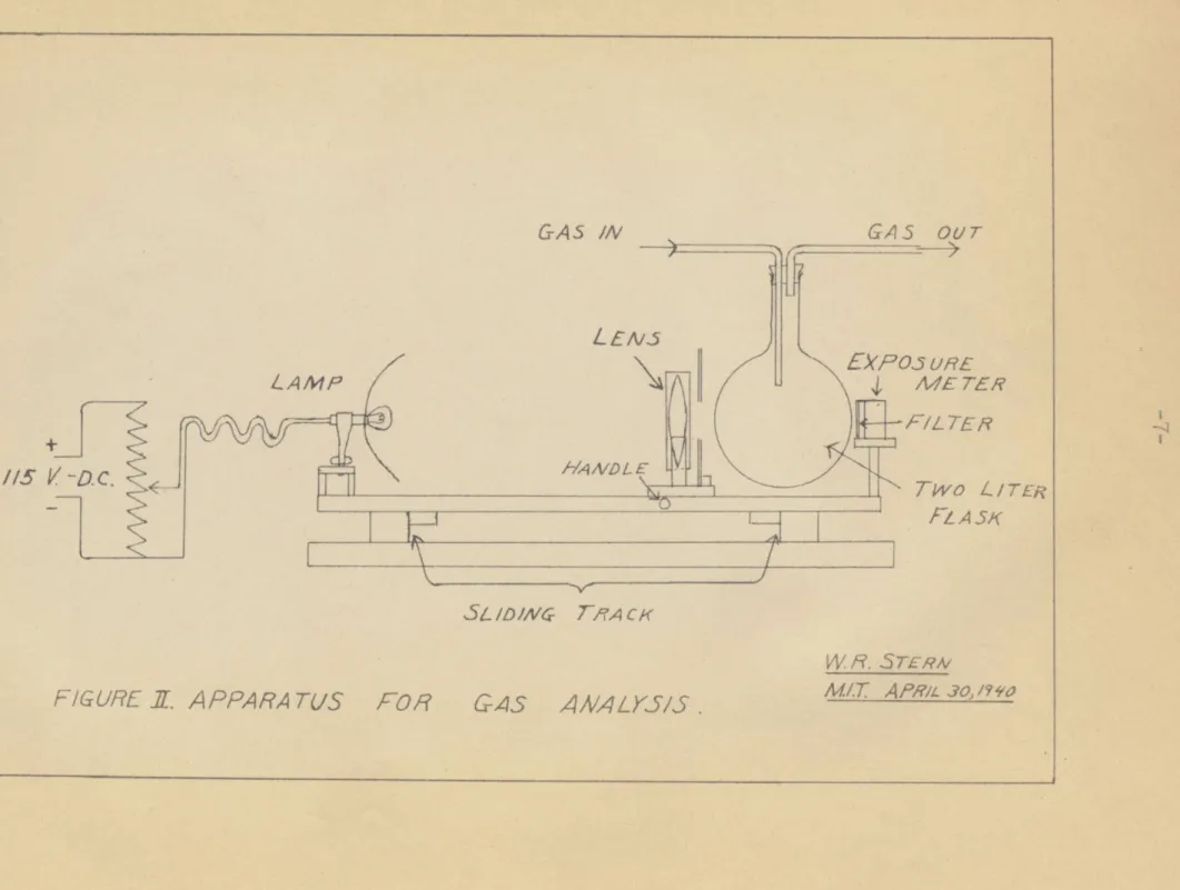
Gas Analysis.
As is shown in Figure I, the mixture of gases passed through the analysis flasks both before entering and
after leaving the tower. The light, lens, filter, and exposure meter were mounted on a sliding track, as shown in Figure II, so that the apparatus could be moved back and forth at intervals to analyze the gases alternately. Space was left between the flasks so that a calibration reading could be frequently taken and the light kept adjusted at the proper intensity. Due to mist formation in the acid runs, the outlet gases had to be corrected for the decrease in effective intensity.
Liquid Analysis.
The NO content of the acid was measured by the addition of a known amount of Ce (SO4)a in 60 7 H0S04, to be followed later by titration to an excess of FeSO4.
EXHAUSr
t
PACKED TowERGCA5
AMALYS/1 4 TRAPSCHEk,
GRADUATE GA5 THERM. CONT FI-OWMETER Cl AW /-I CO/M/A? AIRIA TIC
FIGURE
I.
DIAGRAM
W R.S7ERN M/.T AW.3?,4io MNOOF APPARATU3.
v ROL ASKSFOR
GAS
ANALK5S.
G A 5 OUt/7 V,5 EXPos WUE M /E TEA FILTE RTwo L
FLASK -VII- __ W H. STERNM/.T
APRILO /. ?30 GAS INI-
-p ITR Sl /D/ Cr7-rAcK IF --- A - AMP / -D.C.FIGURE ff. A PPA RA TUS
The NOs content of the caustic was measured by acidifying with HaSO4, adding a known quantity of KMnO4 ,
and titrating to an excess of FeSOt. Laboratory Procedure.
Six runs were made using strong HNO3 and five runs
were made using 6 N. NaOH. Gas and liquid rates were kept constant throughout any single run. Samples of liquid were taken before the NO, was admitted to the air line, these liquid samples being used as representative of the
liquid entering the tower. Nitrogen dioxide was then admitted to the air stream, constant conditions attained, and then the exiting liquid was run into a graduate for a certain time. The graduate was then removed and the liquid analyzed for its NO. content.
Temperatures of air entering and leaving, and of liquid entering and leaving was noted. Inlet and outlet
gases were continually analyzed throughout each run. It was not difficult to keep the entering gas analysis
constant, by means of the light meter and the throttling valve on the NO, container. It was necessary to keep the nitrogen dioxide bomb at about 37 0. to expell the NO,. This was accomplished by means of a constant temperature water bath.
Evaluation of Data.
As developed in the introduction of this report, the values obtained experimentally for the transfer
coefficients according to the equation for mass transfer,
- dN = kYaS dl (Y -Y)= Kya dl (Y - Y
)
(
1 b)were evaluated from the integrated form,
Kya = ( )ent. Yleav.(2
2
).m.
as derived when Henry's Law applies, from
G dY
=
KyaS dl( Y - Y ) . (3)
Transposing,
KYaS
YY~r
-
d
the integral, , may be approximated as, equal to
ent.~lea v. ac Y.. Y*) 1 , and
tent. Yleav. KyaSl(
2 b
Since YF - * is sequal to the Number of Transfer
Units, commonly called the N.T.U. , corresponding
evaluations of the integral shown above may be used to represent the N.T.U. .
The above method of calculating Kya may be applied to the absorption of NOs in caustic solutions also. Recent work has shown gas film resistance to be controlling in
5
this case, and indeed the caustic solution leaving the tower hardly even smelled of NOs. Since Yk is then equal
to zero, the dY dY dY Yent . Y_ = Y-0-
ln
y
leav. and K a = ( )ln ent. (6) Yleav.for the absorption of NO* in 20 % sodium hydroxide solutions.
Preparation of Materials.
All of the nitrogen dioxide used was prepared in-,
the laboratory by the reaction of fuming nitric acid upon
arsenious trioxide in the presence of concentrated
sulphuric acid. The gas was passed through phosphoric
oxide, condensed, and redistilled through phosphoric
oxide.
The strong nitric acid was procured through the.
IV. RESULTS
Sifx runs,:were made, absorbing NOs from itixturessin. air by 96 % HNOs. The results of these runs are
listed-in Table I.
Five runs- were made, using 20 % sodium hydroxide solutions to absorb NOn from mixtures in air. The
results of these runs are tabulated in Table II.
The original data of all the runs- are evaluated
TABLE I.
RESULTS OF ACID RUNS. RUN LIQUID COMPNO
NO Lb.Mol. NOm NO. CU. Ft. LIQUID TEMP. * Cent. Y* Mol. io DMol. Air Inlet Outlet Inlet Outlet
1
.00343
2 .00362.0487,
.o485
3
.00293-
.0346
4 .01015
.00413
.0293.0311
6
.00400
.0331
RUN LIQUID FLOWNO Lb.Mol.Acid NO. Hr. Sq.Ft. 2 3 4
5
6 7.2 7.0 7.2 7.0 10.8 11.0 20 13 20 13 20 14 20. 20 20 14 14. 14-GAS FLOW Lb. Mol. Air. Hr. Sq.Ft. 10.2 10.2 5.1 5.1 10.2 10.2 .0023 .0024 .0020 .0066 .0026 .0025 .0227 .0227, .0170 .0146 .0158 .0167, Y Mol. N0S Mol. Air Inlet Outlet(calc.) .0272 .0272 .0272 .0272 .0272 .0272 .0036.0044
.0077.0061
.0040 N.T.U. yent leav. (Y.- Y )1.m. H. T.U. 12 in N T;U; Kya inches Lb.lol. NO Hr. Cu. Ft. (Y) 1. 2 3 45
9.14 8.20 4.14 3.16 6 5.00 Inlet Outlet RUN NO.1.3-1.5
2.9 3.8 2.4 93-, 83.5 21 32 51
o15-TABLE II.
RESULtS. 0F CAUSTIC RUNS.
N IUI OutCORPe NO. Inlet.-Outlet .0007 .0023 -. 0100 .0009 .0170 10 .0031 .0104 11 .0013- .0105 RUN. Y NO. Inlet 7 .0272 8 .0272 9 .0272 10 .0272 11 .0272
as in Iable I, except K.T.U..
7 8
9
.0169
90.49.6
9.4' 17.9 20.7 1002 5.1 5.1 10.2 10.2 Kya3.6
4.5
2.94.6
Outlet .0192 .0130 .0112 .0205 .0173-N. T . U..35
.89
.28.45.
H. T. U. in- Feet 2.85 1.1 3.6 2.2TABLE III. MATERIAL
RUN NO$ LOST FROM GAS
NO. Lb. Mol. NO2
HR.
BALANCE OF ORIG-INAL DATA.
NO9 GAIN. BY LIQ. Lb. Rol. NOa Hr. RAT10 Large exch. Small exch. 1 2
3
4
5
6 7 8 9 10.0066
.0060 .0025 .0025.0073
.0063
.00241 .00201 .00185 .00268 11 .00324.0070
.0068 .oo48 .0029 .0062.0069
.00238 .00118 .00239 .00201 .00292 1.06 1.13 1.92 1.16 1.18 1.09 1.01 1.70 1.29 1.33 1.11- i~- _
V. DISCUSSION0F RESULTS.
It is seen from the tabulation of material balances, Table III,' that all of the runs except Nos. 3 and 8 check fairly well, and that-runs Nos. l, 6, and 7 check very well as to the amount of NOs lost from the gas equalling the amount gained by the liquid. However, more confidence
is placed.in--the liquid than in the exit gas analysis, and the outlet gas compositions have all been calculated by material balances for the purpose of calculating KYa and H.T.U. values. The results given in Tables I and II are calculated on this basis, but it should be borne in mind that the corrections do not deviate to any great extent from the observed data.
Validity of the calculated results depends also upon the equilibrium data for nitrogen dioxide - nitric acid.,3 and the assumption that there is no appreciable
equilibrium vapor pressure of NOn above the caustic at any time.
The values obtained experimentally for the transfer coefficients need not be corrected for wall effects, since a comparison of data found by Holloway with that found by Allen indicates a very small wall effect in a tower
similar to the one used in this investigation. As.indicated by Holloway,6 as long as the packing size is kept small in respect to the diameter of the tower, the values obtained experimentally for the absorption coefficients will hold reasonably well for large towers.
Inspection of the experimentally determined values of the transfer coefficients would indicate large
resistance to tranfer in the caustic runs and little resistance in the acid runs. Although it is undoubtedly true that the acid runs offered little resistance to
NO. transfer, recent work has shown the gas film resistance to be controlling in the caustic runs, " indicating little liquid film resistance when using 20
%
sodium hydroxide solutions. A large transfer coefficient would then be expected for the caustic runs, since resistance would be encountered to any extent only in the gas film. Using the caustic coefficient as k a for the gas film, and theg
acid overall coefficient, K a, and applying Henry's Law to the solution of NO in very strong HNO3 ,3 one can
theoretically find the acid film resistance,HkLafrom the resistance equation,
K a ka HkLa
The use of the experimentally determined coefficients, converted from KYa to K a units, in this equation would be inconsistent, however, since the liquid film resistance
would result in a negative, meaningless-figure. This-discrepancy may be explained as the effect of any or all of three possible errors in the derivation of the
coefficients. One, the gas phase resistance may not have been controlling when absorbing NO. in the 20
%
caustic.A .large liquid film resistance would then increase the transfer resistance which was used in the above equation as the gas film resistance for the acid runs. This has already been discussed. Two, the NO8 - HN03 equilibrium
data may have been so inaccurate as to produce fantastic results. This is hi Shly doubtful in view of the acid run results of Table I, where the acid analyses show at all times an equilibrium pressure of NOs over the entering or exiting acid that is less than the pressure of the nitrogen dioxide of the gases in contact with the acid. Three, there was considerable nitric acid mist formation in the gas phase during the nitric acid runs. This visible mist was of such an amount as to require a correction in the outlet gas analysis for the decrease in effective intensity of the light reaching the exposure meter.
The most probable hypothesis for the explanation of the discrepancy of the results centers about the mist formation in the gas phase. Mist in the tower might well act as a carrier between the gas and the liquid films. The interfacial area would be increased many fold, due to the nature of such a disperse state, and mass transfer would be correspondingly increased. The liquid and gas streams, flowing countercurrent to each other, undergo close contact and a fair degree of turbulence as they pass through the tower. A small nitric acid droplet formed at the base of the tower, where the air enters, would then pass up with the gas for a short time, absorb
a relatively large amount of NO, and soon approach a an NO equilibrium pressure with the surrounding air. After passing a short distance through the tower, the mist particle, relatively large, would enter the liquid
film, as a result of its inertia causing the particle to follow a straight line motion through the gas stream. This action would take place all along the tower,
resulting in a large transfer of nitrogen dioxide from the gas to the nitric acid.
To increase the complexity of the situation, an exothermic reaction takes place in the gas phase, as evidenced by the small increase in air temperature as the gas passes through the tower. This effect may be explained as the absorption of NOg and HN03 in the water vapor present in the entering air. Sherwood and Chambers
found a similar effect when absorbing nitrogen dioxide in aqueous solutions. 5
Such mist formation would in effect increase the factor, a , which relates the volume of the tower to the interfacial surface. Since the evaluation of the
resistance equation
(
7)
depends upon the constancy of this factor, the impossibility of such an evaluation is apparent.Any conclusion as to whether gas or liquid film resistance is controlling in the absorption of nitrogen dioxide in strong nitric acid cannot be drawn from the experimentaNresults. It can be seem, however, that nitric
acid fumes and droplets in the bulk of the gas form a much larger transfer surface. Furthermore, the effective distance between the transfer surfaces is decreased, and increased transfer through the bulk of the gas should be expected. The gas phase resistance encountered in the acid runs would therefore be nowhere the size of the gas phase-resistance of the caustic runs. This effect is well
brought out by the experimental results. In all the acid runs, the outlet gases contained little more nitrogen
dioxide than that corresponding to the equilibrium pressure of NOs over the entering acid, which was in contact with the exiting gases. In.the caustic runs, however, the exiting gas concentration was far above any such equi-librium. Table III shows that for corresponding liquid and
gas rates, two to three times as much NOs was transferred in the acid runs than was absorbed in the caustic runs.
Since the gas phase resistance would be much smaller for acid absorption than when absorbing in caustic,
overall transfer coefficients should be much larger for the acid absorption. A comparison of Tables I and II shows this to be true. Kya s for the absorption in acid ranged
from 5 to 20 times the overall transfer coefficients for the caustic runs. Such a large increase in K Ya is explain-able by the fact that the driving forces, Y - 1*, for the acid runs were about one fifth to one tenth those of the
caustic runs, and that the difference in entering and leaving gas concentrations, Yent: leav., was about two
to.three times as large for the acid runs as for the caustic. Since KYa was determined by the equation,
Y - Yl~
KYa =
(
ent. a. (2 ),- 1.m.
substitution of the above values of - Ye Yleav. and
A-
in the equation ives Ka s- for the acid runs about five to twenty times those of the caustic runs.
The experimental results also showed that in the caustic runs the Number of Transfer Units cont&ined in.-the tower, averaged about one half, as was expected., with
corresponding H.T.U. values, the Height of a Transfer. Unit, of about two feet. In the nitric acid runs, however, the N.T.U.s for the same tower ranged from sixteen to
five, indicating H.T.U. values of from one to four inches. These results are best explained by the mist formation hypothesis.
Because of the complexity involved and of the relatively small amount of data that was obtained, no attempt was made to correlate KYa s 9
VI. CONCLUSIONS
1. Very large overall transfer coefficients, KYa, for NOs absorption in strong nitric acid were found. The values varied from 25 to 93 Lb. Mol. NOa/Hr. Cu.Ft.(Y). 2. Nitric acid mist formation in the gas phase probably
increases the interfacial area many fold, resulting in the facts that:
a. The overall resistance to NOa transfer is found to be very small.
b. H.T.U. s for the absorption are only about one to four inches.
c. The individual film resistances cannot be determined because of the unknown increase in effective transfer area.
d. Overall transfer coefficients for acid and caustic runs, as experimentally determined, cannot be sensibly correlated. The factor, a, in the respective KYa s do not represent the the same value.
3. Reasonable overall transfer coefficients for NOa absorption in 20 % sodium hydroxide solutions were found. They were all in the vicinity of 4 Lb.Mol. NOs
/
Hr.-Cu. Ft. (Y).
4. H.T.U.s for the caustic absorption were found to be in the vicinity of 2 feet.
balances. In most of the runs the NOa transfer from the air was within 20 % of that absorbed bythe liquid.
6. The continuous flow analysis of NOg - air mixtures by a simple photometric device is satisfactory and
VII. RECOMTENDATIONS
1. All data obtained was for a small tower. This should be kept in mind when applying the transfer coefficients obtained experimentally to the design of larger towers. 2. Further investigation is necessary to ascertain the actual gas ad liquid film transfer coefficients for the absorption of nitrogen dioxide in very strong nitric acid.
3. Very large overall transfer coefficients may be expected when absorbing nitrogen dioxide in concentrated nitric acid. The fuming properties of strong nitric acid probably account for the large values obtained.
4. H.T.U. values of the size of a few inches may be expected for the absorption of NOg in strong HNO3.
5. The continuous flow analysis of NO2 - air mixtures
by a pocket exposure meter is satisfactory and desirable for this type of work.
- c~
APPENDIX A.
EQUILIBRIUM DATA FOR NOg - HN03 MIXTURES.
Von Klemence and Rupp * found the equilibrium data of Table IV for NOa - HNO3 mixtures. The data presented gives total rather than partial pressures over the solutions. The partial pressure of NO, has been
estimated from the data by assuming Raoult's Law to apply to the HNO3 throughout the range used, and subtracting the calculated pressure of HNO3 from the reported total pressure.
The resulting pressures of NO, for various strength acids and at various temperatures,.listed in Table V, were plotted in Figure III. The ln PNOn was plotted versus the temperature, since it was noted that the
straight lines of Figure III would result.
However, Figure III, since it plots logarithms of the pressure, cannot be used to find the pressure of NO,
over dilute solutions of NO, in acid. Since the acid used in the thesis was 23 normal, ( 96 % acid ), and entered the tower at 20 * Cent., points from Figure III for 23 N. acid were plotted in Figure IV as the pressure of NOe versus NO, concentration. The resulting curve, the
straight line of Henry's Law, passes through the origin, and the pressure of NO over small concentrations of NOs may be determined.
- L '~)
TABLE IV.
PRESSURE OF NO *OVER HNOS.
Data of Klemence and Rupp.
wT.% NOs Total Pressure in mm. Hg.
0 * C. 12.5 * 25 * 24 N. (100
)
HNo3 15.9 19.0 21.0 22.8 24.0 25.2 19 N. HNOs 6.9 16. 25.35.
44.53.
17.35.
51. 67. 2.236.
68. 100. 129. 83. 157. 2 34
5 31.5 37.2 42.546.1
48.9 51.0 62.1 71.5 81.5 88.493.5
97.9 0 2 3 45
12.7 27. 44. 59. 74. 90. 23.4 50. 78. 106. 135. 164. 16 N. HNOa 0 2 3 4 5 80. 138. 190. 236. 278.TABLE V.
EVALUATION OF PRESSURE OF NO3 OVER HNO3.
NORMALITY CF ACID PRESSURE o 0. IN VMS. Hg. 12.5 * o
%
NOs 24 19 16 1 % NO* 24 19 16 24 19 16 2 % NOa 24 19 16 24 19 16 3 % NOm 24 19 16 24 19 16 FHNO3 15.9 6.931.5
12.7 2.2 FHNOS 15.7 6.8 FN093.3
9.2 17 ? FHNO3 PNOs .HNO3 FNO$ 15.6 6.-8 5.4 18.2 35 ? ' 15.4'6.6
7.4 28.4 31.2 12.6 2.2 6.0 14.4 34. 30.9 12.5 2.2 12.6 31k5 68. 30. 5 12.3 2..2 15.6 46.7 51 ? 98. 25 * 62.1 23.4 61.5 23.2 10.0 26.8 80 ? 61. 23.0 20.5 55. 138 ? 60. 22.7 28.4 89. 190 ?+
7':
..
~.
.2.
.
.
.i.
.4.
-7t. -1--4 ~-I 144 .1All A~ ~t4 :22-J4444r-44
144
v-~~,144C4
7f.'v
7 Th~ '~7t'
17
V
....
.
-44- -.- t-t7- IRK -L_ 4. +14 TT 4 :.It, 1 .4-:4 -f_ 4I ll -r42~
4I *Tt
14 -4 ___ __ _ t -++.,. _____ : T4 6&."--APPENDIX _B.
CALIBRATION CF INSTRUIMNTS. 1. GAS ANALYSIS APPARATUS.
NO, kept in a stainless steel bomb, was fed into a compressed air line leading to the gas analysis flask. A thermometer was suspended in the flask, out of the light beam, and the gas analysis flask was connected to a liter flask of measured volume. The gases were then piped to the hood.
The meter reading was taken through the empty flask amd without the flask in the beam often, to verify
constant light source and the readings recorded. Then a mixture of NOs and air was passed through the flasks until the exposure meter reading was constant. The meter reading and temperature were recorded and the flow then quickly shut off. The contents of the flask were then analyzed for NOn. The calibration data is listed in Table VI. Sample calculations for the gas analysis will be found under sample calculations.
2. FLOWMETER.
A simple constricted orifice mercury manometer was constructed and used to measure the rate of gas flow. It was calibrated against a previously calibrated dry gas meter. The calibration data is listed in Table VII. Since for an orifice meter,
V = (k/2gh),
squaring and transposing,
h = k' V
(
8b),
and values of h, the height of the mercury column, were plotted agaInst the square of the volumetric rate of flow. The resulting curve was a straight line, from which the calibration curve, Figure VI, was plotted.
TALLE VI.
CALIBRATION DATA FOR GAS AAALYSIS APPARATUS.
METER READING Empty Gas in Flask Flask 180 180 180 180 180 180
180-19
110 18 11534
60
80 TEMP. * Cent. 23- 22-22 22 22 22 21 y Miol. ios MIol. Air.0324
.00329.0357
.00282 -0223 .0126 .00683When mist was encountered, empty flask readings of 140 and 100 were encountered. Curves for these readings were constructed on plot by assuming proportional amount of light transmitted for
correspondin&meter readings. open Path
250
250 250 250 250 250 250 NOTE.4: 4-- liT! ---j 4 f 4 -.4 1.2. '-I.'.--~ Ii
-V
2t+ t-t~~I4? IT0 :; 74-M Z~ ~I~S4~t~
4~,~. - :4..I
~j{ -- 4, fJ2~. .4~Tig2p4-.-4 ~7~f7447fI4j4 4 I : t jtZ p4:4 4' 17 -L 4 4, 4 -t .. ,4i- , 4 1 ik L4 4th-.44
f.1
r
~r
4 ...4 4 , ~ . - .V4 Tt 4+.-A- ~ ~ > ~ A >4_ +r~. -t 4 1
-4-t
-'
t AVA4 1t 44, 4 .4_ 4. _ & 4 . M ~ 4r. 4-4. -A: F- u t -4 -41 4L A ' +-t 4 til .:- 4 - f .4 4- ft ~ ~.4-14.--t
r 1. 1 -ttr 444 r-' -r4 Wt m4,,, _ 4L 4._ _ _ F41J1 t; 4t~j -4 A'~A ~I ~ 2i~&)E4 -4-.. V /Tfli.~22T
21 I ~ '41---.4i i -i 1
!4
1i
1
1
'i
!!
;i
1
;
1
i 1
,
i ;
;1
-,
;
1
,1
' 1
i i !
-i ; 4
I-. 1*14 7W.ArlTm -4
-,. -,T!:.
1-4 + L 11 i 1".H ! - 1-f+.L -t! ! 1 t - i A4 - , ? , 0 6 1 otm 1 1 "! 0 w 1 . : ! x f . 1 1 - .lp r I I - ew. film ilf 0
p
1 , 4 1 11 i 1 , 1 1 0 i 1 - i i 1 , 1- i f &-t t
I
-7--I ~1
-TArLE VII.
CALIBRATION DATA FOR FLOWDMETER.
CAS RATE MANOMETER RDG.
Cu. Ft. /Min. 1.10 1.15 1.55 1.85 2.25 2.8 Cm. H.
1.4
1.5 2.6 3.6 5,6 8.44-1--4
_4
4. -J4it
-4, -:,iI -I s-L m , i' 4 -1-r 44- 44-f 4_----$Ts-t4) L.l 41 A f 4 4UT t4'-4.t 441*+4f41.ft
i
f4V4
tTt4 ,1i
T
..
.
.
..
4.-4+ 1-4- -; 4 .L . . ~I- .- 4-1 1 4 - --- 1 1 -4 +~-
36-APPENDIX C.
DISCUSSION OF GAS ANALYSIS APPARATUS.
The gas analysis apparatus c&nsists-of lamp, filter, and exposure meter, as shown in Figure II. Satisfactory meter readings were found using a 50 c.p. auto lamp,
run at over twenty volts, a rather ineffective reflector, and a poor condensing lens. The path of the light beam through the NO2 - air mixture need only be about 15 cms. to give good results.
Nitrogen dioxide transmits red light, as shown by the solid curve of Figure VII, but a good portion of the greens, wave lengths from 500 to 575 millimicrons, and most of the blues, below 500 millimicrons, are absorbed. Since the light from the lamp has a predominance of the longer wave lengths, light direct from the lamp would pass through NOs with little decrease in intensity. If the reds are cut out, however, by a suitable filter, only the blues and greens could be transmitted. Varying
concentrations of NO* in the light beam would then absorb proportional amounts of the blue - green light, and a sensitive meter reading would result.
The Wratten gelatin filter, Minus Red, No. 44 A, appears to be the most desirable filter attainable. Ith! transmission curve is represented by the dotted line of Figure VII. The reds are cut out, the blues and greens transmitted, and the filter was found satisfactory.
--- / i
-4
A f~K4,
444
17
-4- - -4 o, IIJ~L~~5~ + L 4-4. ;4-14 -,U.4,
tF~-4J -4 -.- zxz~ jl,47T.
!-4 + 4r +- 1 T-+ -4 4 t 4 - n~4 T 1 _ _~~ 4 *~ 44 . i j~j-T 4 4 -- T t.4.4-4 I4 t' f. *f--+ ''~ ,rt 4 *-L44. .. 4. . t Wm -44 4~ Aw 44 ' ;APPENDIX D_.
PREPARATION OF LITROGEN DIOXIDE.
Nitrogen dioxide was prepared from the reaction of fuming nitric acid upon arsenious trioxide, according to the reaction,
AssO3 ++4.HNO 3
=
2 HASO3 + 2N904 -+ HnO (9)where the equilibrium reaction,
NaO4 = 2 NO* (10)
yields a mixture of NO and NO4.
The procedure recommended by Prideaux and Lambourne was followed. To 250 grams of coarsely powdered arsenious trioxide in a liter flask was added a cooled mixture of 315 grams of fuming nitric acid and 150 grams sulphuric acid. The reaction began slightly above room temperature and required external cooling. A. reflux condenser was fitted to effect preliminary cooling of the gas, which was then passed through a U tube containing phosphoric oxide, and then condensed to a liquid in a U tube sur-rounded by ice and salt. The distillation was stopped before the liquid in the flask turned a green color.
The liquid NOe was redistilled, again through P9O , and the product assumed to be fairly pure
NO-Since the HNO3 fumes quickly attack cork and rubber,
all corks were coated with pycine. The use of pycine is not recommended if any better cement can be produced. I
APPENDIX E. ORIGINAL DATA.
The data for all of the runs has been organized into Table IX.
EU'.
TA2LE K.
SUMIARY OF DATA FOR ALL ABSORPTION RUNS.
RUN. LIQUID L G L
Lb. liq. Lb. air Lb.Mol.LiqL NO. Hr. Sq.Ft. Hr. Sq.ft. Hr.Sq.Ft. 96%acid 500 500 500 "i 500 "t 750
"
.765
6N.NaOH 180 180 "t 180 "t 360 "t 360300
300 150 150300
300
300
150 150300
300
7.2 7.0 7.2 7.0 10.8 11.0 9.6 9.6 9.6 19.3 19.3 Lb.lMlol.air Hr. Sq. Ft. 10. 10. 5. 5. 10, 10. 10. -5.5.
10. 10.2
2
1 1 2 2 2 L 2 2 RUN L/G NO. Mol/ivrol/ 1 23
4-5
6
7
89
10 11 0.71 0.69 1.41 1.38 1.06 1.08 0.93 1.87 1.87 1.87 1.87 IN TOWER L Gcc./min. cu. ft./min
72. 70. 72. 70 108. 110. 70. 72. 70. 130. 150. 1.90 1.9 0.95 0.95 1.90 1.90 1.90 0.95
0.95
1.90 1.90 yent. yleav. L. Lb.Mol NO. Lb. Mol. Air .0272 .0272 .0272 .0272 .0272 .0272 .0272 .0272 .0272 .0272 .0272 .0050.0070
.011 .011.0030
.0060
.0186 .0130 .0148 .0178 .0158 1 23
4
5
6 7 89
10 11-41-LIQ. ANALYSIS Inlet
.55
.58
.47 1.63.66
.64
.14' .36 .14 .50 .20 RUN NO. NO. TRANSFER. FROM GAAS Lb. o1.oo66
.0060 .0025 .0025 .0073 .0063 .00241 .00201 .00185 .00268 .00324 QC~T. TO LIQUID NO/Hr. .0070 .0068 .oo48 .0029 .0062 .0069 .00238 .00118 .00239 .00201 .00292 ) . LIQ. TEMP. , C. Iflet Outlet Gm. m. e./
13 13 14 14 14 14 * NO. Mols. INLET 1 23
45
6 7 8 9 10 11 .9023 .0024 .0020 .0066 .0026 .0025 u. T.U. OUTLET .0227 .0227 .0170 .0146 .0153 .0167 ir5
1.8 1.53.0
3.6
.38 .74 .61 .43.55
A.T.U. 1-6 in. 7-11 ft. 1.2 2.4 6.7 8.4.
3.3 2.7 1.35 1.6 2.3 1.8 y a Lb. Mol.NOS Hr. Cu.Ft.93-51 18 15 31
37
3.93.8
3.1 4.4 5.6 '10 cc. Outlet7.95
7.925.65
4.765.06
5.38
2.71 1.60-2.72 1.67 1.68 1 23
4
5
6
7 8 9 10 11 20 20 20 20 20 20 20 2O 20 20 20APPENDIX F'.
AiiALYSIS EITHODS.
1. Liquid Analysis A. Nitric Acid.
The nitric acid was analyzed for its NOS content by the use of Ce(SO4)9 in 60 % sulphuric acid. The acid was poured into an excess of Ce(SO4), and allowed to stand for several minutes. The sulphuric acid probably holds the nitrogen dioxide, forming nitrosylsulphutic acid, until the cerium can oxidize the NOS accor&ing to the following equation:
3 NOS +3 Ce(S04)s +3 HO= Ce(N03)3+Ces(SO4)3+ 3 H9SO4 ( 11)
The excess Ce(S04)a was then titrated to an excess of FeSO&, apcording to the reaction:
2 Ce(S04)a + 2 FeSO4 = Cea(S04)3 + Fee(SC4)3
(
12)using ortho phenanthroline ferrous sulphate indicator.
B. Caustic Solutions.
Nitrogen dioxide is absorbed in sodium hydroxide solutions and reacts according to the equation:
2 NOS + 2 NaCH = NaNO3 + NaNO* + HaO
(
13)
forming the'nitrate and the nitrite. The nitrite content is found by first acidifying with sulphuric acid, while cooling, and then titrating with KIrnO4 .The reaction is as follows:2 K2nO4 +5 NaNOn +3 H*SO4 =-2 MnSO + KISO4+ 5 NaNO3
2. Gas Analysis
A known volume of gas can be analyzed for its nitrogen dioxide content by the same method used to analyze acids. The Ce(SO4)2 solution. is added to the gas, the container sealed and then shaken for
several minutes. The gas should now be completely colorless. The solution is washed out, diluted, and the excess Ce(SO.)g titrated with FeSO4.
APPENDIX __. SAMPLE CALCULATIONS. 1. Sample Calculation of Results.
Run No. 1.
Material balance check.
NOs lost from gas = 1.9
X 60(
ent.~ leav.)359 X 2 273
X
7 6 0 765= .297 (.0272-:0050)
=.0066 Lb.M4ol.NOs/Hr.
NOs gained by liquid
= 7.2 X 60 (7.95
-7
=.0070
Lb.1,1l.NOn/.55) Hr. Correction for material balance,
6o X 0496(.C272-Y. " =0070
Yleav. N.T.U. = ent.~ leav.
(Y - yr)1 .0236
=- .0036
Use ~F~ Y ent= .0021 Yle= .0251leav. (.0272 - .0251) - (.0036 - .0021) ln .0272 .0036 - .0251 - .0021 H.T.U. = 12/N.T.U. = 12/ 13.2 = .91_in.ay
=
( N. T.U.)= .297 013.2)
.29 X 1
= 135 Lb.Mol.N02/Hr. Cu.Ft. (Y).
Calculation of Y used in aoove
at 15*C., 23 N. acid, s. . = 1.49 4 . Y1eav. -9 7. 95 X 100C x 46 1000 x 10 1490 + above
from Figure III, PNOsa
18.8
765 - 18.8
Data used to findY
X 100 = 2.41 wtl% NOs
= 18.8 mms.
)251 Y leav.
is not same as in run 1.
2. Calculation of acid analysis.
10 cc acid sample. Add 50 cc of 0.1 N Ce(S04)0. FeSO4 titration used 20 cc FeSO4 (.1 Normal ).
10 X 1.49 = 14. 9 gms acid 50 X -1 = 5-m-.e. Ce(S0.)s added 20 X .1 = 2 m.e. FeSO4 used
3 m.e. NOs present.
000
=.138
grams NO21 8X 100= .9l
NO*
NOTE:
-46-3. Calculation of caustic analysis
10 cc. caustic sample. acidify, titratetakes 20 cc. of 0.1 N KMlnO
0 X .1 = 2 m.e. pf NOS present.
2 X 46/10Cc = .92 grams NOs
/
10 cc. caustic.4. Calculation of gas analysis
volume of flask is 1040 ccms.,Barom. = 29.5 inches,
temp = 23 * C., Add 20 cc. of 0.087 N. Ce(S04 )., titration took 3.15 cc. of 0.126 N. FeSO4.
22.4 X 29.9 X 296
29.5 X 273 ;o4o/2440o =
=
24.4 liters/gm/mol..0427 Em. mols of gas in flakk.
m.e.NOg = 20 X .087 - 3.15 X .126 =
1.34
m.e. NO. -.
-47-APPENDIX H.
NOENCLATURE.
a = Interfacial surface per unit volumesq.ft./cy/ft.. G = Rate of flow of gas, Lb. Mol./Hr. Sq.Ft.
h = Height of mercury column in cms.
H.T.U. = Height of Transfer Unit in feet or inches. kL = Liquid film transfer coefficient, in Lb. 1ol./
Hr. Sq.Ft. (driving force in mols/mol.sol.free liqd)
k= Gas film transfer coefficient, in Lb. Mol./ hr.
sq.ft.
(
driving force in Y).K = Overall transfer coefficient, units same as ky L = Liquid rate of flow , Lb. Mol./Hr. Sq.Ft.
1 = Packed heightgpf tower.
N = Amount of matter transferred. N.T.U. = Number of Transfer Units. P = Partial pressure in mms. HS.
S = Cross sectional area of tower in sq. ft. 9 = Time
V = Volumetric rate of flow of gas in cu.ft./hr. Y = Concentration of gas, expressed as Kols./iol.
scl. free. gas).
Y = Coontration in -as in equilibriumi with. liquid. uiito same as above.
APPENDIX I. REFERENCES;
1. l.I.T. Plant Design 10.53 Report, January, 1939.
2. Walker, Lewis, McAdams, Gill.," Prin..of Chem. Eng." 429, 3rd Ed..,McGraw Hill Co. 1937.
3. Von Klemence and J. Rupp, "Zeit. fur Anorg.Chemie",
63 194-195 1930.
4. Walker, L.,M.G, " P.C.E.", 486.
5. Chambers,S.F. and Sherwood.,T.K. " Absorp. of NO2 by
Aq. Sol.",. Ind. and Eng. Chem., 29 1415. 6. Sherwood.,T.K. and HollowayF.A. " Perf. of Pakced
Towers" A.I.Ch.E., 36 No. 1 Feb. 1940.
7. Prideaux,E.B. and Lambourne,H. " Textbook of Inorg. Chem." VI part I, 167, C 3-riffin and Co.,London, 1928.