Advanced Flexible Wing Technology Assessment
for the New Strategic Airlifter
by
Jerry M. Wohletz
B.S Aerospace Engineering University of Kansas, 1994
Submitted to the Department of Aeronautics and Astronautics in partial fulfillment of the requirements for the degree of
Master of Engineering at the
MASSACHUSETTS INSTITUTE OF TECHNOLOGY June 1997
© Jerry M Wohletz 1997. All Rights Reserved.
The author hereby grants to MIT permission to reproduce and to distribute publicly paper and electronic copies of this thesis document in whole or in part.
X
A u th o r ... ... ...
Certified by ... ...
S
.,
...
...
...
....
Department of Aeronautics and Astronautics May 31, 1996
Charles Boppe Senior Lecturer, Department of Aeronautics and Astronautics Thesis Supervisor
Certified by ... ...
Mark Drela Asso iate Professor of Aeronautics and Astronautics
I0
, Thesis SupervisorAccepted by ... ... ...
Jaime Peraire Chairman, Departmental Graduate Committee
Advanced Flexible Wing Technology Assessment
for the New Strategic Airlifter
by
Jerry M. Wohletz
Submitted to the Department of Aeronautics and Astronautics on May 23, 1997, in partial fulfillment of the requirements for the degree of Master of Engineering
Abstract
An Advanced Flexible Wing (AFW) technology assessment as applied to the New Strategic Airlifter (NSA) is reported in this thesis. The seed for this project originated from an assessment study performed on a generic strike fighter where significant potential weight savings were identified. The AFW concept - also known as Active Aeroelastic Wing (AAW) - is composed of several
elements that serve to make aeroelastic deformations an asset rather than a limitation on the wing's design. The focus of this assessment study is to determine if the rollcontrol element of the AFW concept can be used for the NSA, and what is the potential wing structural weight savings that can be achieved by using the technology. The load alleviation, drag reduction, and flutter suppression elements of AFW are not explored nor are the effects of reducing the torsional stiffness on the flutter
characteristics. The thesis objectives were completed. Based on a maximum allowable aileron deflection of 250, the roll control aspect of AFW does not offer potential wing structural weight
savings if a traditional inboard aileron configuration is used as the primary roll control device at high dynamic pressures. However, the concept does offer a potential wing structural weight reduction of approximately 8% if an outboard aileron configuration is used as the primary roll control device at high dynamic pressures. Furthermore, the aileron control configurations do not reverse within the flight envelope. Sensitivity analysis revealed that reducing torsional stiffness results in a reduction in aerodynamic spanwise efficiency. However, the spanwise efficiency can be recovered with the addition of washin angle at the tip. Finally, requirements analysis raised physical design questions relating to cost, structural weight, aerodynamic efficiency, reliability, maintainability, and
supportability. The assessment recommendation is that further analysis is required to assess the other potential benefits of AFW such as load alleviation, drag reduction, and flutter suppression for
the NSA.
Thesis Supervisor: Charles Boppe
Title: Senior Lecturer, Department of Aeronautics and Astronautics Thesis Supervisor: Mark Drela
Acknowledgments
I would to thank all of those people who made this thesis possible. First and for most, I would like to thank my fiance, Tina Park, and my family for all of the support they provided me throughout this project. Additionally, I would like to thank my office mates and teammate Shawn Hanegan for being there when it counts. Thanks guys!
I would also like to thank the faculty for their support and advice. Special thanks goes out to Charlie Boppe, Professor Mark Drela, and Visiting Professor Terry Weisshaar from Purdue University. Their contribution to this project was above and beyond the call of duty. I would also like to thank my research advisor Professor James Paduano for being patient and understanding. Last but not least, I would like to thank Professor Mark Ewing at the University of Kansas for his insightful advice.
In addition to the faculty support, I would like to express my appreciation to our industry contacts. I would like to thank my employer McDonnell Douglas Aerospace. Specifically I would like to thank Darin Groll for fighting for my educational leave of absence, and Rudy Yurkovich for providing assistance and computer resources. Additionally, I would like to thank Lockheed Martin who sponsored the project, provided the baseline configuration, provided their computer tools, and most importantly, they provided direction. Thank you Mark Norris. In addition to Lockheed, Wright-Patterson Airforce Base personnel had a vital role in the success of this project. Special thanks goes out to Ray Kolonay for those late evening conversations.
Table of Contents
Abstract...
3
Acknowledgments ...
5
Table of Contents ...
7
List of Figures ...
9
List of Tables ...
11
Chapter
1
Introduction...
...
13
1.1 Background Work ... ... 14
1.2 NSA Assessment Study Objectives... ...
... 15
1.3 T hesis O verview ... 19
Chapter 2 Requirements Analysis
...
...
21
2.1 Requirements Hierarchy ...
... ...
21
2.2 Explicit Customer Needs...
...
23
2.3 Implicit Customer Needs ...
... 25
2.5 Requirements QFD Build...
... 30
2.6 Conclusions .... ... 33
Chapter 3 Baseline Configuration and Mission
...
....
. 35
3.1 NSA Baseline Configuration... ... 35
3.2 Wing Structural Layout ...
...
38
3.3 Wing Material Selection... 45
3.4 Baseline Missions and Design Point Selection ... ... . 46
3.5 V-n Diagram for Selected Design Point ... 47
3.6 Roll Performance for Selected Design Point.. ... 50
3.6 Conclusions ... ... 51
Chapter
4 NSA W ing Design and Sensitivity Analysis...
....
55
4.1 NSA Wing Design Process Overview ... ... .. 55
4.2 NSA Wing Design ... 57
4.2.1 ASTROS Structural Modeling ... ... ... 57
4.2.2 Aerodynamic Modeling... ... ... ... 61
4.2.3 Multidisciplinary Optimization ... ... 63
4.3 NSA Sensitivity Analysis ... 81
4 .4 C onclu sion s ...
87
Chapter 5 Conclusions and Recommendations...
... 89
5.1 Conclusions ...
89
5.2 Recommendations ...
93
5.3 Contribution . ...
94
References ...
95
Appendix A Operational Requirements Document
...
. 99
Appendix B DOC Assessment Study for Narrow-Body Commercial Transport. 105
List of Figures
Figure 1.1 Aeroelastic Effects on Steady State Roll Rate ...
... 17
Figure 1.2 Allowable Aileron Deflection Versus Required Wing Structural Weight for Desired
R oll P erform ance...
18
Figure 2.1 Requirements Hierarchy Build Example ...
... 24
Figure 2.2 Typical DOC Breakdown for Narrow-Body Transports ...
. 27
Figure 2.3 D O C Relationship M atrix ...
... 29
Figure 2.4 N SA Requirem ents QFD ... ... 32
Figure 3.1 NSA LGA180D Configuration Three-View ...
... 36
Figure 3.2 Typical Transport W ing Layout...
39
Figure 3.3 Supercritical Airfoil Ordinates...
42
Figure 3.4 Selected Wing Structural Arrangement for the NSA...
44
Figure 3.5 NSA Baseline Operation M ission...
... 46
Figure 3.5 V-n Diagram for Initial Operational Cruise Point ...
... 49
Figure 4.1 N SA W ing D esign Process ... 55
Figure 4.2 ASTROS Design Model Schematic...
59
Figure 4.4 Maximum Allowable Aileron Deflection Versus Required Wing Structural Weight
for Level I Roll Performance... ...
70
Figure 4.5 Aileron Effectiveness Ratio Required Versus Required Wing Structural Weight for
Level I R oll Perform ance ...
... 71
Figure 4.6 Aileron Effectiveness Ratio Required for Level I Roll Performance Versus Maximum
Allowable Aileron Deflection ... 72
Figure 4.7 Maximum Allowable Aileron Deflection Versus Potential Wing Structural Weight
R ed uction ...
74
Figure 4.8 NSA Minimum Weight Wing Structural Deflections for the Outboard Aileron
Configuration at M =0.69, N z=2.5 g's ...
75
Figure 4.9 NSA Wing Minimum Weight Structural Deflections for the Outboard Aileron
Configuration at M =1.07, Nz=2.5 g's ... . ...
76
Figure 4.10 NSA Wing Minimum Weight Structural Deflections for the Outboard Aileron
Configuration at M =0.86, N z=-l.0 g's...
77
Figure 4.11 NSA Wing Minimum Weight Structural Deflections for the Outboard Aileron
Configuration at M =0.50, Nz=-1.0 g's...
78
Figure 4.12 NSA Wing Minimum Weight Structural Deflections for the Outboard Aileron
Configuration at M =0.82, Nz= 1.0 g's ...
79
Figure 4.13 ASW ING M odel Schematic ... 82
Figure 4.14 Control Effectiveness Versus Equivalent Airspeed ...
83
Figure 4.15 Span Efficiency Versus Percentage Change in Torsional Stiffness for M=0.82,
h= 32,000 ft, and 1.0 g's...
... ... 84
Figure 4.16 Span Efficiency Versus Washin Angle for M=0.82, H=32,000 ft, and 1.0 g's. ... 85
List of Tables
Table 2.1 Subset of Explicit Customer Needs...
... 23
Table 2.2 DOC Relationship M atrix Results ...
28
Table 2.3 Explicit and Implicit Customer Needs ... ... 30
Table 2.3 Explicit and Implicit Customer Needs ... ... 33
Table 3.1 Aluminum Material Properties used in NSA Wing Design ... 45
Table 3.2 V-n Diagram Parameters for Initial Cruise Point... ... 47
Chapter 1 Introduction
Cost of aerospace products is one of the most critical issues that face the aerospace engineering
industry. For aircraft, the cost is proportional to the gross take-off weight; thus, cost reduction can
be achieved by weight reduction. Throughout the history of aviation, there has been significant
advances made in the reduction of the aircraft weight that include the use of aluminum and
composite materials. Another proposed approach to reducing the aircraft weight is the Advanced
Flexible Wing (AFW) concept, and this is the focus of this thesis.
The AFW concept
-
also known as Active Aeroelastic Wing (AAW)- is composed of several
elements that serve to make aeroelastic deformations an asset rather than a limitation on the wing's
design. These elements include the use of wing deformation for roll control, load alleviation, and
drag reduction. All of these elements involve controlling the spanwise lift distribution through wing
warping, which is a concept as old as powered flight itself. The Wright brothers took advantage of
the flexible nature of their wings to roll their aircraft through mechanical wing warping.
Traditionally, aircraft wings are designed for bending and torsional stiffness considerations;
however, the idea of AFW is to design the wing only for bending stiffness. The bending stiffness
impacts mainly static and dynamic stability. Wing divergence and flutter denote static and dynamic
instability respectively. The torsional stiffness impacts mainly performance and dynamic stability.
Performance here means whether or not the elastic wing can produce adequate roll. Currently,
transport and fighter wings are designed such that the wing will not fail for the expected design
loads and that the wing will have inherent performance that is adequate for the desired mission.
Thus, the concept of AFW is to design transport or fighter wing such that the wing will not fail for
the expected design load, but the wing's passive performance will be inadequate for the desired
mission. As a result, an active approach will then have to be employed to obtain the desired
performance.
By designing the wing's structure for bending stiffness only, there exists an opportunity for a
reduction in wing's structural weight. However, this can only be realized if the torsional stiffness is a
design driver. If the design of the wing is governed by bending strength only
-
resulting
aeroelastic twist effects are negligible
-
then the potential weight savings from the AFW concept
will be minimal. On the other hand, if the design of the wing is governed by bending and torsional
strength so that the resulting aeroelastic twist effect is significant, the AFW concept may provide
potential weight savings.
1.1 Background Work
The background work on AFW as been primarily focused on military fighter applications. In the
mid 1980s, Rockwell International Corporation pioneered and advanced the AFW concept. In
1991, a number of wind tunnel tests at NASA Langley were performed to demonstrate the AFW
concept, and an entire section of the AIAA Journal of Aircraft was devoted to the discussion of the
results [Ref 1.1-1.10]. "The key program accomplishments included single- and multiple-mode
flutter suppression, load alleviation, and load control during rapid roll maneuvers, and
multi-input/multi-output multiple-function active controls test above the open-loop flutter boundary"
[Ref 1.1].
In 1994, Lockheed Martin and Rockwell teamed to perform a joint AFW assessment study on a
generic strike fighter. Their investigation was focused on the potential weight savings that might be
realized by using AFW for a baseline aircraft which was a single engine, single seat, conventional
takeoff and landing generic strike fighter [Ref 1.11]. Two wings were investigated, one conventional
and one AFW, and both of them shared commonality of planform, thickness to chord ratio, and
control surface layout. The results of their assessment study offered a potential gross takeoff
weight reduction of 7.1%, and potential empty weight savings of
8.7%.
In addition to weight, the
following potential benefits were identified:
* Control Surface Reversal Compensation
* Flutter Suppression
* Load Alleviation
* Multipoint Twist Optimization * Elastic Mode Control
The recommendations were that a higher fidelity analysis is required in order to further substantiate the potential savings, and design integration issues and consequences need to be evaluated.
In 1997, McDonnell Douglas Aerospace, Rockwell International Corporation, NASA, and the USAF teamed to perform a joint AAW flight test program [Ref. 1.12-1.13]. The aircraft selected for the flight test program is the F/A-18 Hornet. Currently, the operational F/A-18 uses aeroelastic wing warping for roll control in the transonic speed range, which is accomplished by deflecting the leading edge flaps. This is believed to be the first modern use of this technology in a production aircraft. The first flight of the AAW F/A-18 is expected in the year 2000.
1.2 NSA Assessment Study Objectives
The focus of this assessment study is to determine if the roll control element of the AFW concept can be usedfor the New Strategic Airlifter NSA, and what is the potential wing structural weight savings that can be achieved by using the technology. More specifically, the present objectives are to:
1. Identify the minimum weight design with no torsional constraints for roll performance, 2. Identify the region of aileron control: non-reversed or reversed,
3. Identify the potential weight savings based on the maximum allowable aileron deflections, and 4. Identify the sensitivities of torsional stiffness on reversal speed, span efficiency, and maximum
strain.
Other aspects of AFW including the load alleviation, drag reduction, and flutter suppression and the effects of reducing the torsional stiffness on the flutter characteristics are not addressed in this study but merit attention in future investigations.
For this study, the Lockheed Martin Aeronautical System Company generously provided a baseline AFW configuration - the NSA which is a proposed replacement for the aging C-141 fleet. The NSA concept is a medium size military cargo plane proposed to perform both military and
commercial missions. Military roles include deployment, tanker and airdrop. Commercial missions include overnight delivery and intermodal. The military deployment mission is used for this
assessment study.
To further expand the concept of aeroelasticity and its relationship to the objectives, two
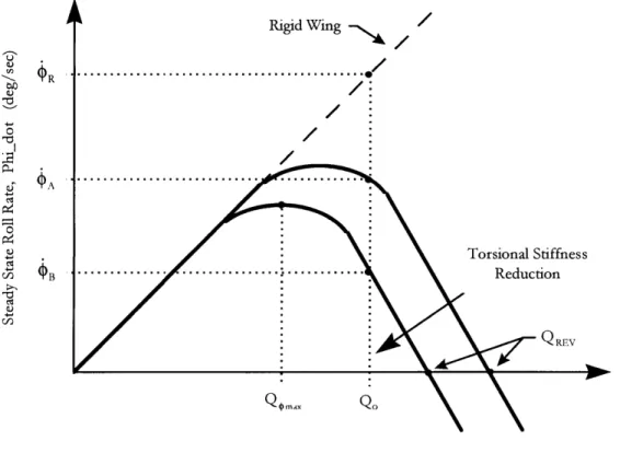
illustrations will be used. The first illustration will demonstrate the effects of speed on roll control. Figure 1.1 illustrates the steady state roll rate for a given aileron deflection as a function of speed and torsional stiffness. For a rigid wing, the roll rate is perfectly proportional to the true airspeed. For a flexible wing, this is true only at small low dynamic pressures. However, as the dynamic pressure increases, the steady state roll rate of the flexible wing becomes progressively smaller that that of the rigid wing. At a Qtmax, the maximum attainable roll rate for a given aileron deflection is achieved. Above that dynamic pressure, the roll rate decreases and eventually becomes zero at the reversal
dynamic pressure, Qev . Above the reversal dynamic pressure, a positive aileron deflection produces a negative steady state roll rate.
Reduction of the torsional stiffness reduces the reversal dynamic pressure, the maximum attainable steady state roll rate, and the speed at the maximum roll rate. The figure also characterizes the Aileron Effectiveness Ratio (AER) which is the ratio between the flexible and rigid steady state roll rates:
AER
-Thus, for a given Mach number, a reduction in the torsional stiffness results in a reduction in the AER. It is worth noting that the AER is sometimes referred to as the aileron flex to rigid ratio.
Rigid Wing /
-
Torsional Stiffness
-j
... ...
...
Reduction
QREV
Dynamic Pressure, Q (psf)
Figure 1.1 Aeroelastic Effects on Steady State Roll Rate
This figure illustrates the aeroelastic effects for variations in airspeed; what follows is a look at the
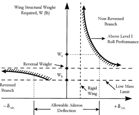
aeroelastic effects for variations in wing structural weight. Figure 1.2 illustrates the constant speed
aileron deflection required for the desired roll performance versus the wing structural weight. Note,
the required wing structural weight is composed of the structural weight required for bending
constraints and the structural weight required for torsional constraints. Additionally, structural
weight variations are directly proportional to variations in torsional constraints if the bending
stiffness constraints are held constant. The infinite structural weight corresponds to rigid body
torsional constraints, and the low mass limit corresponds to zero torsional constraints. Thus, this
representation illustrates the variations in structural weight due to the variations in torsional
constraints with the bending constraints held constant.
For a rigid wing, which has infinite weight, there exists a lower bound on the aileron deflection
required to satisfy the desired roll performance. As the structural weight decreases, the required
aileron deflection increases, and becomes infinite at the reversal weight. Below the reversal weight,
the required aileron deflection increases from negative infinity. As the structural weight decreases further, it approaches the minimum mass limit which represents a wing that is designed for bending considerations only.
Wing Structural Weight Required, W (lb) Wa I Reversal Weight Wb Reversed Branch Non-Reversed Branch Above Level I Roll Performance I I I I I I I r I I I 0 I I I I I
SRigid
nWing Low Mass Limit- 6 AILAIL Allowable Aileron
Deflection AIL
Figure 1.2 Allowable Aileron Deflection Versus Required Wing
Structural Weight for Desired Roll Performance
Figure 1.2 allows for the determination of the wing structural weight required for a desired roll performance, if the maximum aileron deflection is given. This maximum allowable aileron
deflection is the deflection before the aileron tears off the wing. For a traditional wing design, the wing weight would remain in the non-reversed branch of this figure and this corresponds a wing structural weight Wa. However, if the AFW concept is employed, the wing will be allowed to reverse and the resultant weight would be Wb. Thus, the potential weight saving due to the AFW concept is:
1.3 Thesis Overview
Chapter 2.0 details the requirements analysis that was performed on the NSA. It includes a
discussion of the Operational Requirements Document (ORD) that was provided by Lockheed.
The chapter also contains a discussion of the requirement hierarchy and the resultant extraction of
customers needs. A discussion of implicit customer needs is presented. A quality function
deployment analysis is performed on the combined explicit and implicit customer needs. The
quality functional deployment generates a prioritized list of technical requirements to satisfy the
customer needs identified in the ORD.
Chapter 3.0 defines the technical requirements for the NSA wing design. The chapter details the
NSA configuration provided by Lockheed. Then, a wing structural layout followed by materials
selection is identified. The baseline mission is identified and a single point in the flight envelope is
selected for this evaluation. For this flight point, a V-n diagram is constructed, and six resultant
design points are identified. Finally, the roll performance for the flight point is discussed.
Chapter 4.0 contains the NSA wing design and sensitivity analysis. The first section in this chapter
outlines the design process methodology used for the wing design. Following this section, the
synthesis of the wing is discussed. Finally, sensitivity analysis is performed.
Chapter 5.0 contains the conclusions, recommendations, and contributions of this AFW assessment
study, and Chapter 6.0 contains the References.
Chapter 2 Requirements Analysis
The purpose of the requirements analysis is to translate customer's words into technical requirements that are used for the physical design process. The requirements analysis for this
project is based on the Operational Requirements Document (ORD) for the New Strategic Airlifter
(NSA). The ORD is contained in Appendix A. The NSA was selected by Lockheed as the baseline
configuration for which to perform the AFW assessment study. A detailed description of the NSA
is contained in Chapter 3. The key concept of the requirement analysis that relates to the AFW
assessments is that an initial requirement analysis must be performed on the entire aircraft. Results
of this global requirement analysis are technical requirements which the design must demonstrate to
satisfy the customer's needs. From these global technical requirements, specific technical
requirements for the wing and that of AFW technology are identified.
This chapter details the extraction of derived technical requirements for the AFW wing from the
ORD. The requirements analysis procedures consisted of sequential steps which are structured to
ensure that the derived technical requirements are in concert with the customer's words. The first
step of the analysis is to construct a requirements hierarchy. The second step is to extract explicit
customer requirements from the requirements hierarchy. The third step is to generate implicit
customer needs. The final step is to compile the explicit and implicit customer needs and perform a
Quality Function Deployment (QFD). Results of the QFD are derived technical requirements
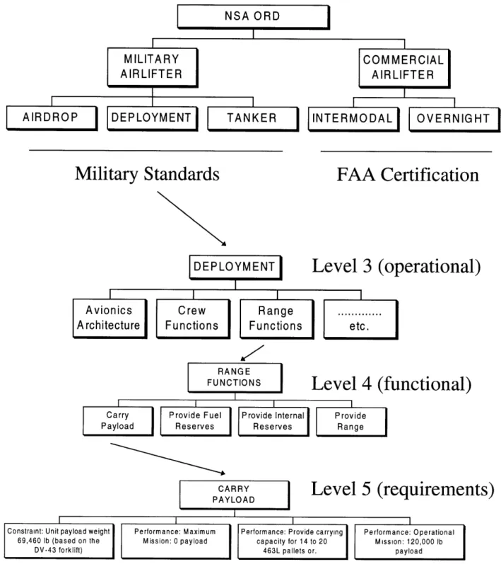
which ideally satisfy the customer's needs specified in the ORD.2.1 Requirements Hierarchy
A requirements hierarchy was constructed based on the ORD. The procedures used in constructing
the requirements hierarchy are as follows:
1. separate customer needs into mission scenarios;
2. extract operational requirement functions; and
The NSA has both military and commercial missions. For the military role, the ORD specifies a
deployment, airdrop, and a tanker mission. The commercial scenarios consist of an overnight and
an intermodal mission. Operational requirement functions are defined as operational actions or
activities needed to solve the customers needs. [Ref. 2.1] Requirement types are defined as follows:
* Performance requirement types are flexible requirements that measure how well the function
performs.
* Reliability requirement types are flexible requirements that measure how well a function
performs over time.
* Maintainability requirement types are flexible requirements that measure how well the system
can be fixed if failure occurs.
* Extensibility requirement types are flexible requirement the measure the ability of the design to
adapt to new changes or requirements.
* Constraints requirement types are non-flexible requirements that place limits on the design.
Note, constraints affect the design trades between the flexible requirements.
An example of the how the customer's words were dissected into the a requirements hierarchy
format is detailed below:
Customers Words: "Design Life of 40,000 flight hours with a maintenance man-hours per flight
hour of 20.0"
Requirement Function:
Provide Reliability/Maintainability
Requirement Types:
Reliability Requirement:
Design Life of 40, 000 Flight Hours
Maintainability Requirement:
Maintenance Man-Hour per Flight Hour of 20. 0
Through this analysis, a requirement hierarchy was constructed. An example of the requirements
hierarchy is illustrated in Figure 2.1.
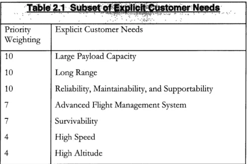
2.2 Explicit Customer Needs
The explicit customer needs were extracted from the requirements hierarchy. The basis for selection
of the explicit customer needs was dependent on the emphasis placed on the requirement in the
ORD. Due to the immense size of the requirements hierarchy and the resultant explicit customer
needs, a subset of the explicit customer needs was selected for this analysis
-
the subset reflects the
primary design drivers for the NSA. Furthermore, the subset of explicit customer needs was
prioritized, and appropriate weighting terms are illustrated in Table 2.1:
Table
2.1 Subsetofx
t C4ustomer Nee.ds
Priority
Explicit Customer Needs
Weighting
10
Large Payload Capacity
10
Long Range
10
Reliability, Maintainability, and Supportability
7
Advanced Flight Management System
7
Survivability
4 High Speed 4 High Altitude
Military Standards
DEPLOYMENT
I
FAA Certification
Level 3 (operational)
I
I
I
i
Avionics
Crew
Range
Architecture
Functions
Functions
etc.
Level 4 (functional)
RANGEFUNCTIONS
I I' I I
Carry Provide Fuel Provide Internal Provide
Payload Reserves Reserves Range
I
CARRYLevel 5 (requirements)
2.3 Implicit Customer Needs
The NSA's ORD obtained from Lockheed was primarily focused on performance requirements. As a result, the explicit customer needs identified in the previous section are only performance related. Basing the requirements analysis entirely on performance related requirements would most certainly result in unacceptable derived technical requirements. Today, cost is a critical requirement
-sometimes a constraint - in any military procurement program, and is also a primary factor in a commercial program. Thus, cost considerations must be included in the requirements analysis. This was accomplished through implicit customer needs.
To incorporate cost considerations into the requirements analysis, the concept of cost has to be quantified in terms of customer needs. Traditionally, cost is quantified in terms of Life Cycle Cost, LCC. The LCC includes the following divisions: [Ref. 2.2]
* Research, Development, Test, and Evaluation Cost
- Cost associated with conceptual, preliminary, and detailed design
* Acquisition Cost
- Cost associated with manufacturing and profit
* Operating Cost
- Cost associated with operating the airplane which includes Indirect Operation Cost and Direct Operating Cost
* Disposal Cost
- Cost associated with the disposal of an aircraft.
Based on data presented in Reference 2.2, the Operating Cost typically ranges from 50-75% of the LCC, and the Acquisition Cost ranges from 25-50% of the LCC. Thus, the Operating Cost is the primary contributor to the LCC. However, due to budgetary constraints, military procurement often weighs the Acquisition Cost equally to or above that of the Operating Cost.
The Operating Cost is typically subcategorized into Indirect Operating Cost (IOC) and Direct
Operating Cost (DOC). IOC division includes all cost that is associated with passengers, ground
operations at the gate, promotions, sales, entertainment, and general administration. Traditionally, it
is assumed that the airplane designer has little influence on this category of cost. DOC division
includes cost associated with flight hours, and is highly influenced by the designer.
At this point, the cost considerations have been quantified in terms of LCC, and the Operating Cost
has been determined to be the primary contributor to LCC. Furthermore, the Operating Cost has
to be quantified as Indirect Operating Cost and Direct Operating Cost from which it is assumed that
the designer only affects the Direct Operating Cost. Thus, the cost consideration will be expressed
in terms of Direct Operating Cost.
The objective now is to translate the DOC into tangible implicit customer needs. Due to the lack of
actual DOC data, empirical estimates of DOC were used. [Ref. 2.2] The empirical estimates for
DOC are subcategorized as follows
* Flying Cost
* Maintenance Cost
* Depreciation Cost
* Miscellaneous Cost
The Flying DOC estimate is further subcategorized to include crew, fuel and oil, and insurance
costs.
In order to use the empirical DOC estimates, an airplane preliminary design database is required.
However, a military cargo configuration database was not available. Therefore, a preliminary design
database was obtained from previous work by the author which included a DOC study of
narrow-body aircraft. [Ref. 2.3] A reproduction of the DOC study has been duplicated in Appendix B. It is
assumed that the general trends of DOC for a narrow-body commercial transport are representative
of the DOC for military cargo planes. This assumption is a necessity due to the lack of better
information.
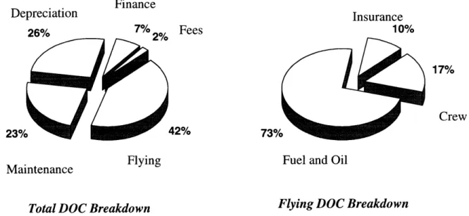
The DOC estimates were performed on three different narrow-body aircraft: MD-90-50, B737-300, and A320-200. Furthermore, DOC estimates were computed for the following ranges: 1000 NM, 1500 NM, 2000 NM, and 3000 NM missions were applicable. The key assumptions used for these calculations are referred to Appendix C. Based on the DOC estimates for the cited aircraft and missions, an average is computed. The results of which are illustrated in Figure 2.2.
Finance Depreciation Insurance 26% 7% 2% Fees 10% 17% Crew 23% 42% 73%
Maintenance Flying Fuel and Oil
Maintenance
Total
DOC
Breakdown
Flying
DOC
Breakdown
Figure
2.2 Typical DOC Breakdown for Narrow-Body Transports
The next step in determining the implicit customer needs is to select the important empirical parameters that affect the distributions presented in Figure 2.2. This is accomplished by using a relationship matrix to prioritize the parameters which influence the empirical estimates of the DOC. The relationship matrix is illustrated in Figure 2.3. The subcategorization of the DOC is included in the left column of the figure, and the weighting terms reflect the percentages illustrated in Figure 2.2. The parameters which influence the empirical estimation are listed across the top. Reference 2.2 contains a detailed description of the parameters listed. Relationship weighting terms were inserted in the matrix to reflect the importance of the parameter on the particular DOC estimate. A quadratic weighting scheme was selected for this matrix build. A weighting of 9 reflects a strong
weighting of 1 reflects a moderate effect on the estimate. No negative weighting terms are used in this matrix build. Finally, the DOC weighting estimates are multiplied across the matrix by the
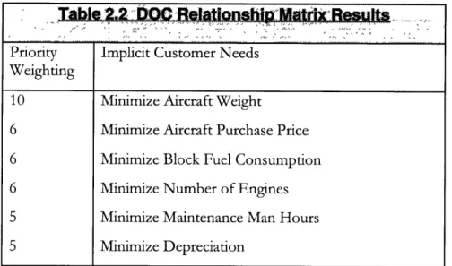
relationship weighting terms, and then summed vertically. The results of this relationship matrix are attained by normalizing the vertical summations by the maximum value, and then grouping the technical parameters. The technical parameters obtained thus represent the implicit customer needs, and the resultant normalized prioritization will serve as the implicit customer needs weighting terms. Table 2.2 illustrates the implicit customer needs and the weighting terms that were obtained from the DOC relationship matrix.
Table 2.2 V=Relatonshin Malt Results
Priority Implicit Customer Needs Weighting
10 Minimize Aircraft Weight
6 Minimize Aircraft Purchase Price 6 Minimize Block Fuel Consumption 6 Minimize Number of Engines
5
Minimize Maintenance Man Hours
5
Minimize Depreciation
Other Depreciation Maintenance Flying
Cost Cost Cost Cost
3 3 3 3
~3
3 33 3 3 3 3 3 33 oc~ M~ m> m>1>o W 2. IDc DIDcI(lD( I( D( (D cDD (0n I110 > m > CL3 3 3 0~r
-" 5" 5 5 ; 5" K , C") 1) 13 1) C :'3~_T~
_ 0! OlO'.LP _ -" 'a" -2-) -) U) U " -0o~(
ai C U0 a) 'a CDDpe, -t.
_>. o o u
-'
. {/}-
j~lolk
-WdD CD 0 n n ( o c S_. 0-0 CD cn 0 0(<o CD ' 0 D , CD6 279 1 Minimize Block Fuel Consumption
2 93 , Minimize Fuel Price
1 31 Maximize Fuel Density
1 31 Minimize Weight of Oils and Lubricants
6 258 _ CD 1W Minimize Number of Engines
2 76 c c - Minimize Annual Block Time
1 31 , Maximize Oil/Lubricant Density
1 31 Minimize Oil/Lubricant Price
1 63 I Minimize Number of Pilots/Crew
6 284 0 (0 ( - Minimize Aircraft Purchase Price
0 12 o Maximize Annual Block Time
3 110 w co o - - C Maximize Block Speed
1 25 Minimize Flight Delays
5 225
m
Minimize Maintenance Man Hours1 45 c
a
Minimize Labor Rate10 437 w __w_ W - Minimize Aircraft Weight
0 20 - Minimize Takeoff Thrust
1 60 ce Minimize Engine Purchase Price
1 60 0M aximize Time Between Engine OverhaL
5 225 rMCmm inimize Depreciation Rate
0 10 -1 Maximize Number of Engines
0 10 Maximize Engine Price
0 5 Maximize Price Of Avionics
5 225 (M0au aximize Depreciation Period
2.5 Requirements QFD Build
At this point in the requirements analysis, the explicit and implicit customer needs have been
identified. The customer needs include both performance and cost considerations, and these results
are summarized in Table 2.3. It is seen from this table that the customer needs are conveniently
categorized to cost, performance, and operational drivers. The weighting terms of the combined
customers needs reflect the weighting terms illustrated in each of the explicit and implicit builds.
However, there is one exception; the minimized aircraft purchase price from a DOC perspective
had a weighting of 6, but because of the importance of purchase price in military procurement, the
purchase price weighting was increased to a 10.
-,T.abe
1.3 EXp4 t
Istomer
.k.lit
~ad
N
eeds:
Cost Drivers:
Performance Drivers:
10 Minimize Aircraft Takeoff Weight
10 Large Payload Capacity
10 Minimize Aircraft Purchase Price
10 Long Range
7
Minimize Block Fuel Consumption
4
High Speed
7
Minimize Number of Engines
4
High Altitude
6
Minimize Maintenance Man Hours
4
Long Endurance
6
Minimize Depreciation
Operational Drivers:
10 Reliability, Maintainability, and Supportability (R, M,& S)
7
Advanced Avionics
7
Survivability
The final step of the requirements analysis is to perform a Quality Function Deployment (QFD)
analysis on the prescribed customer needs. This was accomplished by using the guidelines specified
in Reference 2.4. The relationship between the technical requirements and the customer needs is
requirements is produced by vertically summing the columns of the relationship matrix. Furthermore, conflicts between technical requirements are identified in the correlation matrix.
Given the customer needs illustrated above, a QFD matrix was constructed for the NSA, and it is illustrated in Figure 2.4. The customer needs along with their weightings are represented in the left vertical columns. The technical requirements are represented across the top of the matrix, and the
technical requirements are grouped into the following categories: * Aircraft Empty Weight,
* Aerodynamic Efficiency, * Engine Efficiency, * Engine Sizing, * Manufacturing, * Technology, and * Support.
The categorization of technical requirements was assumed by the author based on previous airplane design heritage. The intent of the list is to represent some of the primary design drivers which affect the customer needs. The list is not intended to be all inclusive.
As with the DOC relationship matrix, the QFD relationship matrix reflects the importance of the technical requirements for a particular customer need. Again, a quadratic weighting scheme was selected for this matrix build. A weighting of 9 reflects a strong positive affect on the customer need, a weighting of 3 reflects apositive affect on the customer need, a weighting of 1 reflects a moderate effect on the customer's need, and a blank reflects no effect. Additionally, negative weighting terms were included in this matrix. Note, negative weighting terms are not traditionally included in QFD matrix builds. The author decided to include them for the purpose of highlighting the conflicts between customer's needs and technical requirements, and a -3 weighting reflects a negative affect on the customer's need. The -3 was selected versus -1 or -9 because it was an intermediate value.
Support Performance Cost 0 (j o Dnvers _ C- 0-- o 00- 0 O° 34 0 K Z c M (t -"15L5CD C ) 0 Z 00 D-215 0 -Minimize Surface Area 56 m0 Clearance 108 aa O 0 a Maximize Sea-Level Thrust 93 : Maximize Wng Loading 84 Hgh Cruse Mach Number 240 Design for Manufactung 240 ..- Desgn for Assembly 108 Commercal Pracces 244 _ . Reduce Part Count 118 v ! . Number of Different Matenals 261 c AdvancOptimized ACruise Lift Distribution 150 -Advanced Manufacturng Processea 56297 Hurbine Inlet TeCmponentsue ---m0 56 1 -W w C) Tip Clearance 370252 -Minimize Number of Enginesty 150 5 Standardsximize Sea-LGround Equvel ipment 18910 c Maximize Litt Coefficient 93--- Maximize Wing Loading 84 0 6 I ow D o le, High Cruise Mach Number 240 D -Design tor Manufacturing 244 w CD w m Reduce Part Count 118 w -1 1( Number of Different Materials 261 1 0 dvanced Avionics 1501 1C C dvanced Manufacturing Process 297 CHigh Reliability Components 237 1 I C I -I Modular Design 252 :1 Systems Commonality 150 v Standards Ground Equipment
Finally, the customer's needs weighting terms are multiplied across the matrix by the relationship
weighting terms, and then summed vertically. Results of this QFD matrix are attained by
normalizing the vertical summations by the maximum value, and then grouping the technical
requirements. The technical requirements obtained thus represent the derived technical
requirements. Table 2.4 illustrates the derived technical requirements and their relative importance
(weightings) to the design of the NSA.
2.6 Conclusions
The requirements analysis was performed for the New Strategic Airlifter. Explicit customer's needs were identified from a requirements hierarchy build. Implicit (derived) customer's needs were identified based on Life-Cycle Cost. Customer needs were prioritized, and a QFD analysis was
Aircraft Empty Weight
10 Minimize Structural
6 Reduction in System and/or
COST
-
PERFORMANCE
DESIGN TRADES
R,M & S
Aerodynamic Efficiency
5
High Reliable
6 Maximize Cruise L/D
5
System Commonality
4 Maximize Aspect Ratio
4 Reduce Parts Count
4 Optimize Cruise Lift
4 Design for Manufacturing and
4 Minimize Surface Area
4 Modular Design
performed. Finally, prioritized technical requirements were extracted from the QFD. The results of
the technical prioritization are illustrated in Table 2.3. Additionally, three primary technical
requirements categories were identified: aircraft empty weight, aerodynamic efficiency, and
reliability, maintainability, and supportability (R,M&S).
The purpose of the requirements analysis was to translate customer's words into technical
requirements for which to initiate the physical design process. Given the requirements analysis for
the entire aircraft, the categorization of derived technical requirements were applied to the AFW
assessment study. The questions this study should answer in relation to the derived technical
requirements are as follows:
1. Wing Structural Weight
What are the potential weight savings with an AFW for high aspect ratio configuration?
What are the potentialpenalties
for system integration and complexity?
2. Aerodynamic Efficiency
What are the potential aerodynamic efideng benefits/drawbacks?
* Induced Drag
* Control Surface Reversal
* LoadAlleviation
* Elastic Mode Control
3. Reliability, Maintainability, and Supportability
What are the reliability, maintainabili, and supportability issues that may affect the implementation of
AFW technology?
Numerous design trade studies are needed to completely and to properly evaluate the derived
technical requirements. However, as outlined in Section 1.2, only a small fraction of the design
trades is addressed in this project. This AFW assessment study focused on the potential weight
savings, and the resultant effect of AFW on the aerodynamic efficiency. Reliability, maintainability,
and supportability issues were not addressed.
Chapter 3 Baseline Configuration and Mission
This chapter outlines the baseline configuration and mission for the AFW assessment study. In
particular, this chapter contains a general discussion of the baseline configuration of the New
Strategic Airlifter. Additionally, the baseline wing parameters, wing structural arrangement, and
material selection is presented. A flight envelope point is presented along with a V-n diagram.
Finally, the Military Specification for roll performance is reviewed. The objective of the chapter is
to outline the assumptions, constraints, and specifications for the AFW assessment.
3.1 NSA Baseline Configuration
The proposed role of the NSA is to provide a replacement for the aging C-141 Starlifter fleet. The
primary military role of the NSA will be that of deploying U.S. strategic forces throughout the world
in both times of crisis and times of peace. The NSA will also have airdrop and tanker capabilities so
as to provide multiple functionality. Additionally, due to the rapidly expanding commercial
airfreight market, the airlifter will have commercial applications ranging from overnight package
services to high priority oversized shipping.
Several NSA configurations were provided by Lockheed Martin Aeronautical Systems. [Ref. 3.1
through 3.6] These included variants with two engines and four engine with various cargo
capabilities. The particular NSA configuration selected for this assessment study is the LGA180D, which is a single stick - accommodation for only a single row of 463L pallets - twin engine concept. A three-view of the geometric configuration is provided in Figure 3.1. The attributes of
the LGA180D configuration are as follows:
TYPE: Twin Engine, Long Range Military Airlifter
LGA 180D) - 001
Wing Aiea Wing Sweep
Aspect Ratio
Cargo Box Width Range Payload Cruise Speed MTOW OWE 2 CF6 - 80C2 lEngines 3425.8 1"'**2 15.0 tleg 9.5 13 ft 3,300 inm 120,000 Ib1 0.82 M 399,330 11b 165,984 II) 61,500 Ib) ea. 318.2 m** 2 35.0 deg 9.5 4.0 mi 6,112 km 54,432 kg 0.82 M 181,136 kg 75,290 kg 27,896 kgl' 187.4 ft (57.1 in) 51.7 ft (15.8 in) -- L
LANDING GEAR: The landing gear is an underfloor storage pod configuration similar to that
used for the C-5.
POWERPLANT: Two CF6-80C2 (each 61,500 lb. static, uninstalled) high-bypass turbo-fan
engines. This engine is a major redesign of the CF6-80A1 for higher thrust and improved specific fuel consumption. The fan diameter is 93 inches, and it has a four-stage compressor and 5.5 stage turbine.
ACCOMINDATIONS: Flight crew requires two pilots and the cargo crew requires 1 loadmaster.
Up to 6 flight crew can be accommodated for extended missions. The airlifter can transport both palletized bulk and oversized cargo.
DIMENSIONS, EXTERNAL
Wing Span 180.2 ft
Wing Chord: at root 29.3 ft
at tip 8.8 ft
Wing Aspect Ratio 9.5
Wing Sweep (quarter chord) 35.00
Length Overall 187.4 ft Fuselage: Length 174.5 ft Max Diameter 17.58 ft Height Overall 51.7 ft Tailplane Span 38.5 ft DIMENSIONS, INTERNAL Floor Length 55.8 ft Floor Width 13.0 ft AREAS Wing, gross 3426. ft2 Fin 496.2 ft2 Tailplane 336.0 ft2
WEIGHTS AND LOADINGS
Basic Operating Empty Weight 165,984 lb. Max Usable Fuel 114,931 lb.
Gross T-O Weight 399,330 lb. Max Wing Loading 113.8 psf
PERFORMANCE
Max Cruise Speed 502 knots
Range 3,300 NM
Critical Field Length 7,488 ft
3.2 Wing Structural Layout
The primary function of a wing is to produce lift, and in doing so, the wing must transmit the lift forces to the fuselage. The aerodynamic functionality is provided by the airfoil, and the load transfer is accomplished by the wing's torque box.
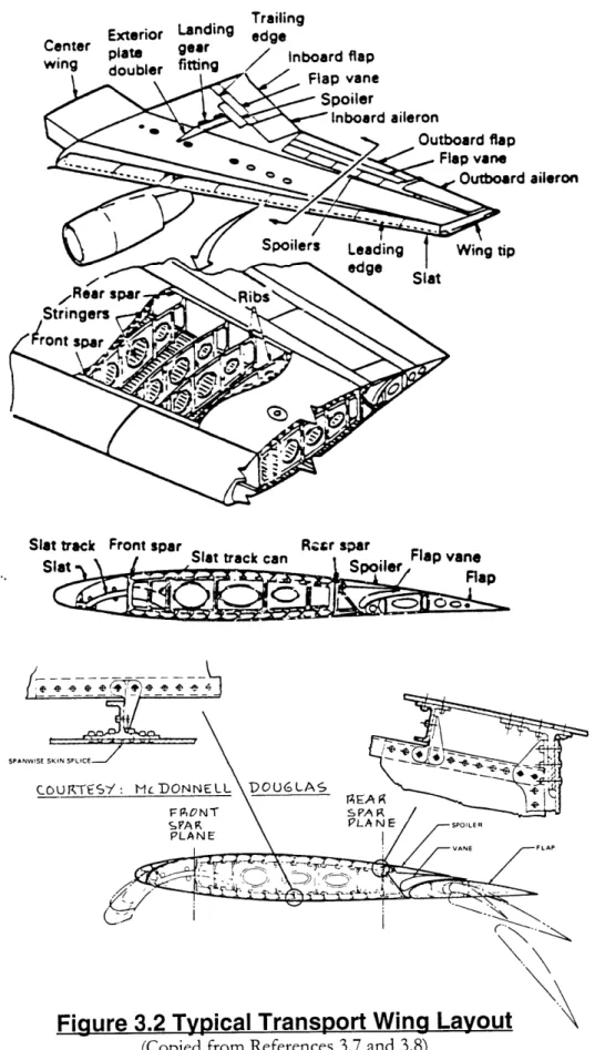
Wing structural design is based on a semimonocoque structure were the strength is derived from the skin and the skeleton structure inside the wing. The primary spanwise members of the structural skeleton are the spars, stringers, and shear webs, and the primary chordwise member is the rib. A typical transport wing is illustrated in Figure 3.2. Of particular interest in Figure 3.2 is the primary structural elements that are identified in the figure. Spar caps, which define the corners of the wing's torque box, are structural members whose primary function is to provide bending stiffness both in-plane and out-of-plane. In-plane bending is produced primarily from lift, and out-of-plane bending is generated from the drag, the engine thrust, and the lift in high angle of attack conditions. Shear webs, which bridge the gap between the upper and lower spar caps, are structural members that transmit shear loads generated by the in-plane bending loads to the fuselage.
Trailing
Exterior Landing edge
Center a,, er / Inboard flap wing doubler fitting nbar fap Flap vane Spoiler Inboard aileron Outboard flap ---. ~ ,,Flap vane o Outboard aileron SPANWISE SKIN
Figure
3.2 Typical Transport Wing Layout
The skin of the aircraft provides dual functionality. The primary function of the skin is to provide torsional stiffness. Furthermore, the skin provides bending stiffness in both directions. Like the spar caps, the skin is located the greatest distance from the centroid of the torque box, and this results in a significant contribution to the bending stiffness. Due to the dual functionality, the skin transmits both bending and torsional loads to the fuselage. Another structural member illustrated in Figure 3.2 is the stringer. Stringers are attached to the upper and lower skins, and serve the primary function of transmitting in-plane bending moments to the fuselage; thus, relieving the skin of its bending stiffness functionality. Additionally, stringers prevent local buckling of the skin. Nui, Reference 3.7, suggests that a stringer area to skin area ratio of about 1.7. Thus, for a skin-stringer panel, the stringers provide most of the bending stiffness and the skin provides most of the torsional
stiffness. The net effect of this combination is a lighter weight structure.
Finally, the primary function of the ribs is to maintain the airfoil external shape along the chord of the wing without appreciable distortions. Ribs also transmit the sectional chordwise loads to the spar caps and shear webs.
Considering the structural functionality prescribed above, a baseline structural arrangement was selected for the assessment study. The NSA wing planform parameters were provided by Lockheed Martin Aeronautical Systems, Ref. 3.1 through 3.6, which serve as a basis for the structural layout. The NSA wing planform parameters are as follows:
WING PLANFORM DATA
Span 180.2 ft Taper 0.3 A.25Cbar 350 Root Chord 29.3 ft Tip Chord 8.80 ft MAC 20.9 ft Area 3,425.8 ft2 AR 9.5 Anhedral 20 Twist -30 @ tip
t/c: @ wing/body 16.3%
t/c: @ .95bbar/2 12.0%
OUTBOARD AILERON DATA
Chord: 75%-100% Cbar
Span: 70%-90% bbar/2
FLAP DATA
Type: Single-Slotted Fowler
Chord: 70%-100% Cbar
Span: Wing/Body-65% bbar/2
High-Lift Chord 70%-110% Cbar
High-Lift Deflection 450
SPOILER DATA
Chord: 70%-80% Cbar
Span: Wing/Body-65% bbar/2
In addition to the wing planform illustrated above, an inboard aileron was added to this
configuration. The need for the inboard aileron came about because of the inability to model the spoilers for the analysis presented in Chapter 4. The primary functionality of spoilers is to provide roll control power at high speeds; thus, considering that the objective is roll performance at high speeds, the inboard aileron was substituted for this assessment study. It is important to note that inboard ailerons, also known as high speed ailerons, are common for transports. Typically, when the high-lift system becomes a dominant design driver and limits the available space for the inboard aileron, a designer resorts to the use of spoilers for high speed roll control power.
The inboard aileron was sized such that the rigid wing aileron control power derivative of the inboard aileron was equal to that of the outboard aileron. Based on this sizing, the planform parameters for the inboard aileron are as follows:
INBOARD AILERON DATA
Chord: 75%-100% Cbar
The structural arrangement of the wing was assumed based on conventional standards presented in
References 3.7 and 3.8. There are two spars with the front spar located at
15%
of the chord and the
rear spar located at
65%
of the chord. As specified by Reference 3.5, the wing is a root-root
attachment. The wing's configuration is a straight tapered wing versus a cranked wing due to the
fact that the concept is a high wing configuration and that the landing gear is fuselage mounted. Rib
spacing was assumed to be 24 inches. The rib spacing was altered at various spanwise stations to
account for the engine integration and flight control surface attachment points. No leading edge
devices were included. The stringer spacing was assumed to be 12 inches. In accordance with
design for manufacturing and assembly considerations, the stringers and the ribs are oriented parallel
and perpendicular to the rear spar respectively.
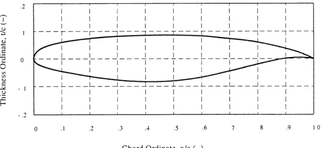
To finalize the structural arrangement, a generic supercritical airfoil was used for the baseline wing
configuration. The airfoil is representative of the airfoil used on the Boeing 777, Reference 3.9, and
it is illustrated in Figure 3.3.
S . .2 .3 .4 .5 .6 7 8 .9 10
Chord Ordinate, x/c (-)
Figure 3.3 Supercritical Airfoil Ordinates
Considering the selected structural disposition and airfoil, a 3-dimensional schematic of the
structural arrangement was generated, and the half-span layout is illustrated in Figure 3.4. The four lines that traverse the span of the wing illustrate spar caps, and the shear webs are symbolically represented as the structural sheets between the top and bottom spar caps. The non-highlighted lines that transverse the span between the front and rear spars illustrate the stiffeners. The ribs are illustrated by the sectional airfoil shapes that transverse the span. Finally, the shaded surface represents the top and bottom skin.
In addition to the basic structural layout, the aileron, flap, engine pylon, and the engine were included in this layout representation. The utility of this model will become evident with the
3.3 Wing Material Selection
The material selection for the wing is based on typical transport wing data presented in References 3.7 and 3.8. An all metallic wing is assumed for this assessment study. Trade studies should be performed to assess the impact of metallic and non- metallic wing structure on the AFW concept, and this is recommended for future investigations.
The wing's upper skin and stringers are designated to be AL-7075-T6 which has desirable compression characteristics The wing's lower surface, stringers, spar caps, and shear webs are assumed to be AL-2024-T3 due to its desirable strength characteristics and corrosion resistance. The material properties, illustrated in Table 3.1, were obtained from the military handbook, MIL-HDBK-5E.
"+-"-l 31&'m
+ t i---
i i
san---Material/Form AL-7075-T6 Sheet AL-2024-T3 Sheet AL-2024-T3 Bar Specification QQ-A-250/12 QQ-A-250/4 QQ-A-200/3 Thickness/Areas .040-.125 in .010-.128 in .750-1.50 in2 Ft, ksi 78 64 65 Fty, ksi 70 47 46 Fcy, ksi 69 39 41 Fsu, ksi 47 39 33 E, 10 ksi 10.3 10.5 10.8 Ec, 10 3ksi 10.5 10.7 11.0 G, 103 ksi 3.9 4.0 4.1 11 .33 .33 .33
(0,
lb. in3 .101 .101 .101Note, all properties correspond to the A Basis and L direction were applicable.
--3.4 Baseline Missions and Design Point Selection
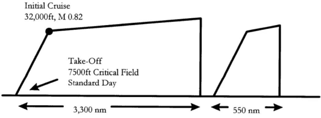
The NSA ORD specifies two baseline missions in terms of range and payload. The operational mission consists of a 3300 NM range and a payload of 120,000 lb. The maximum mission consists of a 6000 NM range with no payload. For both missions, the range is specified as the distance from departure to the intended landing field with no refueling and no wind. Both missions are to take-off from a 7500 x 86 foot, level, dry paved runway, standard day, at sea level with no obstacles. The initial cruise is specified to be 32,000 ft at 0.82 Mach, and the maximum cruise altitude is 39,000 ft. Additionally, the maximum airspeed is either 350 KEAS or 0.86 Mach. This breakpoint in
maximum airspeed occurs at approximately 24,000 ft in a standard atmosphere. Finally, both missions must have enough fuel reserves to fly an additional 550 NM to an alternative landing field. The baseline mission profile is illustrated in Figure 3.5.
Operation Deployment Mission: 120,000 lbs Payload
Initial Cruise 32,000ft, M 0.82
Take-Off
7500ft Critical Field
A0*
Standard Day3,300 nm
)
550 nmFigure
3.5 NSA Baseline Operation Mission
The initial cruise point in the operational mission is selected for the AFW assessment study because the point represents the heaviest weight and highest dynamicpressure combination. Recall that
* aeroelastic effects are more prominent at high dynamic pressures; * heavy weight translates to larger wing loading; and
heavy weight translates to a larger rolling moment of inertia (unburned fuel is in the wing) which inhibits rolling performance.
Ideally, the assessment study would investigate the entire flight envelope including take-off and landing load cycles.
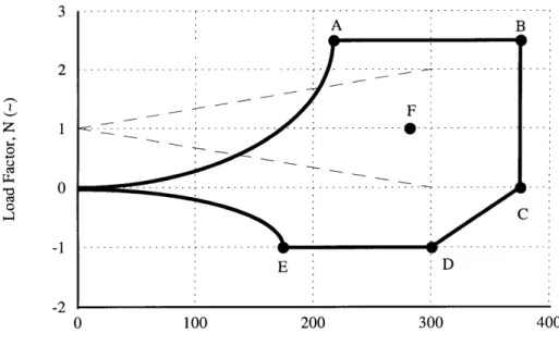
3.5 V-n Diagram for Selected Design Point
Given the design point
on MIL-A-8861 (ASG),
selection, a V-n diagram was constructed. The V-n diagram build was based and the parameters that were used for this build are contained in Table 3.2.
Altitude
Initial Cruise Weight Wing Area
Positive CLMAX CD
@
Positive CLMAxNegative CLMAX CD @ Negative CLMA Positive Load Factor, nLIMIT
Negative Load Factor, nLIMIT
Mean Geometric Chord CLa Maximum Speed
32,000 ft
380,000 lb.
3426 ft21.5
0.1123
-1.125
0.0710
2.5
-1.0
20.83 ft
6.20 rad
-1239.1 KEAS
The initial cruise weight of 380,000 lb. was determined by assuming a 5% mass credit for the taxi, take-off, and climb segments of the mission profile. The gross take-off for the operational mission is 399,330 lb.. The CLMAx for cruise was provided by Lockheed, Reference 3.10. The CD at the
CLMAx was calculated based on empirical methods based in Reference 3.11, and the drag polar was
determined to be:
CD = 0.0180 + 0.0419 CL2
The negative CLMAX was assumed to be 75% of the positive CLMAx. The CL, was determined through empirical estimates contained in Reference 3.11. The load factors were based on
specifications for a medium cargo/transport in MIL-A-8861(ASG). Finally, the maximum cruise speed corresponding to M 0.86 at 32,000 ft was determined to be 239.1 KEAS based on standard atmosphere.
The results of the V-n diagram build are as follows: * 2.5 g Stall Speed: 239.1 KEAS * 2.5 g - 0.0 g Dive Speed: 370.1 KEAS * -1.0 g Max. Speed: 296.1 KEAS * -1.0 g Stall Speed: 174.6 KEAS
Additionally, it was determined that the initial operational cruise point is not gust critical. Figure 3.5 illustrates the V-n diagram.
It is important to note that corners of the V-n diagram represent the worst case scenarios for the wing structural design for the given design point in the flight envelope. Imagine an aircraft at an initial altitude of 32,000 ft. in a straight level flight, and the pilot pushes the yoke forward to perform a push-over maneuver. The push-over maneuver is performed at a constant -1.0 g load factor; thus, the pilot initiates the maneuver by commanding maximum negative Clmax, and then trades negative angle of attack for speed to maintain the desired load factor. In doing so, the aircraft transitions into a dive, and eventually reaches a terminal velocity (steady state dive speed). As the aircraft plunges towards the ground, the pilot pulls back the yoke at about 20,000 ft to perform a pull-up maneuver. The pull-up is performed at a constant 2.5 g; thus, the pilot trades speed for angle of attack, or as the speed decreases, the angle of attack increases to maintain 2.5 g's. After the pull-up maneuver, the pilot proceeds with a straight and level flight at an altitude below 20,000 ft and
f F 1< C C E D -2 0 100 200 300 400
Equivalent Airspeed, V (KEAS)
Figure 3.5 V-n Diagram for Initial Operational Cruise Point
(h=32,000 ft, M=0.82, W=380,000 lb.)
hopefully above the ground. The maneuver just described is illustrated in Figure 3.8 through the boundary points from points E through A. Points E to D represent the push-over maneuver, and Points D to C represent the transition from horizontal flight to a steady state vertical flight
trajectory. Points C through B represent the steady state dive from 32,000 ft to 20,000 ft. Points B to A represent the pull-up maneuver.
It is important to note that the maneuver prescribed above is a longitudinal maneuver only, and lateral maneuvers should be considered in the wing structural design. The lateral directional maneuver is performed about point F in the flight envelope. Ideally, the wing design should be performed with coupled longitudinal and lateral maneuver such as a rolling pullout; however, the computational analysis presented in Chapter 4 can only perform uncoupled maneuvers. The details of the lateral maneuver will be detailed in the next section.
Considering the longitudinal and lateral maneuvers described above, the six design points were obtained from the n diagram, and these points are detailed in Table 3.3. A further tutorial of a