M A S S A C H U S E T T S I N S T I T U T E O F T E C N O L O G Y 1 3 . 4 1 3
P R O J E C T I N N A V A L S H I P C O N V E R S I O N S P R I N G 2 0 0 3
ADVANCED GUN SYSTEM
(AGS) BACKFIT
DD-988 N
AVAL
G
UNFIRE
S
UPPORT
S
HIP
C
ONVERSION
L T J U L I E H I G G I N S L T J A S O N R H O A D S L T M I C H A E L R O A C H
EXECUT IVE SUMMARY
Installation of the AGS in USS THORN can be accomplished while retaining most of the baseline capabilities of the platform. The outcome of the analysis of alternatives indicated that placement of AGS mount aft, in place of Mount 52 and the NATO Sea Sparrow Missile system, as the preferred alternative. Among the reasons for its selection was the 304 round capacity of its magazine, the retention of more major war-fighting capabilities, and the minimization of cost and baseline ship impact. This configuration results in degradation of the AAW self-defense capability of the modified USS THORN, due to the loss of the NSSMS. However, with the full preservation of the baseline strike and anti-submarine capabilities, the ship remains a viable war-fighting platform.
The modified USS THORN exhibits structural characteristics largely unaffected by the installation of AGS. Electrical and auxiliary systems are seen to be capable of accommodating the gun system, although slight doctrine changes such as placing additional pumps online or splitting the electrical bus may be necessary. The electrical system will experience an increase of 719kW under battle conditions, best configured by splitting the bus to prevent the electrical draw of the gun from tripping other systems offline. The fire main system experiences an increased demand of 2438gpm, mostly due to a very high flow magazine sprinkling system, with the installation of the AGS. Placing additional fire pumps online can accommodate this increased demand. The chilled water system experiences an increase in demand of 31gpm, also correctable by placing additional chilled water pumps online if necessary.
Stability and seakeeping characteristics of the modified USS THORN are seen to differ only slightly from the baseline configuration. Further, all requirements of AAO-AA-SPN-010/Gen-Spec, DDS 100-1, 2, 4, 5, 6, 7, DDS 079-1 and DDS 079-2 are met by the modified USS THORN.
EXECUTIVE SUMMARY ...II
1.0 -- MISSION NEED ...1
1.1 -- NATIONAL GUIDANCE AND POLICY...2
1.2 -- CURRENT CAPABILITY ASSESSMENT...2
1.2.1 -- Anti-Submarine Warfare ...4
1.2.2 -- Anti-Surface ...4
1.2.3 -- Anti-Air ...4
1.2.4 -- Communications and Tactical Information...5
1.2.5 -- Engineering...5
1.3 -- MISSION NEED...5
2.0 -- DESIGN REQUIREMENTS AND PLAN ...7
2.1 -- REQUIRED OPERATIONAL CAPABILITY...7
2.2 -- CONCEPT OF OPERATIONS/OPERATIONAL SCENARIOS...7
2.3 -- GOALS, THRESHOLDS, CONSTRAINTS, AND STANDARDS...8
2.4 -- RECOMMENDED ALTERNATIVES...9
2.5 -- DESIGN PHILOSOPHY...9
3.0 -- CONCEPT EXPLORATION ...11
3.1 – OPTION 1: FORWARD MOUNT AT FRAME 70 ...11
3.1.1 – War-Fighting Capabilities Assessment...11
3.1.2 – Weight and Stability Analysis ...12
3.2 – OPTION 2: AFT MOUNT AT FRAME 440 WITH STANDARD MAGAZINE...13
3.2.1 – War-Fighting Capabilities Assessment...14
3.2.2 – Weight and Stability Analysis ...14
3.3 – OPTION 3: AFT MOUNT AT FRAME 440 WITH EXTENDED MAGAZINE...15
3.3.1 – War-Fighting Capabilities Assessment...16
3.3.2 – Weight and Stability Analysis ...16
3.4 – FINAL BASELINE CONCEPT DESIGN...17
4.0 – FEASIBILITY STUDY AND ASSESSMENT ...19
4.1 – DESIGN DEFINITION...19
4.1.1 – Principal Ship Characteristics Summary...19
4.1.2 – Arrangement ...19
4.1.3 –Electrical and Auxiliaries ...22
4.1.4 – Structural Design...25
4.1.5 – Weights, Stability and Margins...25
4.1.6 – Survivability...26
4.2 – PERFORMANCE ANALYSIS (MISSION/OPERATION SCENARIOS)...27
4.2.1 – Mission...27
4.2.2 – Seakeeping ...27
4.2.3 – Underway Replenishment ...27
4.3 – COST...28
4.3.1 – Total Estimated Cost...28
5.0 -- DESIGN CONCLUSIONS...29
5.1 – SUMMARY OF FINAL CONCEPT DESIGN...29
5.2 – FINAL CONCEPT DESIGN ASSESSMENT AND CONCLUSIONS...29
5.3 – AREAS OF FURTHER INVESTIGATION...29
LIST OF REFERENCES...30
APPENDIX A – MISSION NEED STATEMENT FOR INSTALLATION OF THE ADVANCED GUN
SYSTEM ON SPRUANCE CLASS DESTROYERS ...31
APPENDIX B – OPTION 1 DETAILS...33
APPENDIX C – OPTION 2 DETAILS ...40
APPENDIX D – OPTION 3 DETAILS ...45
APPENDIX E – STRUCTURAL ANALYSIS ...51
APPENDIX F – STABILITY ANALYSIS ...58
APPENDIX G – PERMEABILITY ...83
APPENDIX H -- SEAKEEPING...85
1. 0 -- MISS IO N N EED
The purpose of this study is to design and evaluate the installation of the Advanced Gun System (AGS), designed for the DD(X) class of ship, on a Spruance-class destroyer as a “technology shake-down” platform. By testing and evaluating the performance of the AGS prior to lead-ship installation in the DD(X) program, significant risk mitigation can be accomplished. Therefore, this early technology insertion is essential to the success of a major weapon system in the DD(X) program. This feasibility-level investigation represents the groundwork for at-sea testing of the AGS on an existing Spruance-class platform. As a follow-on to the Arleigh Burke-class program, the Navy is evaluating concepts for a new generation of surface combatants that is expected to provide the future fleet with the necessary capabilities and to be built in sufficient quantities to provide the required number of ships for overseas presence and war-fighting missions. The DD(X) will initially replace older ships of the Spruance-class (DD-963) and Oliver Hazard Perry-class (FFG-7).
The DD(X) program encompasses a family of three surface combatant ships: a destroyer, a cruiser, and a smaller littoral operations craft. The DD(X) family will support the National Security and Military Strategies, which require the Navy to provide forces to support the major missions of Conventional and Strategic Deterrence: Land Attack, Theater Air Defense, Sea Control, Forward Presence, and Strategic Sealift. Required capabilities delineated in the Mission Needs Statement (MNS) include: Power Projection; Battlespace Dominance; Command, Control and Surveillance; Joint Force Sustainment; Non-combat Operations; and Survivability / Mobility.
The DD(X) program will provide a baseline for spiral development of the DD(X) and the future cruiser or "CG(X)" with emphasis on common hullform and technology development. The Navy will use the advanced technology and networking capabilities from DD(X) and CG(X) in the development of the Littoral Combat Ship with the objective being a survivable, capable near-land platform to deal with threats of the 21st century. The intent is to innovatively combine the transformational technologies developed in the DD(X) program with the many ongoing R&D efforts involving mission-focused surface ships to produce a state-of-the art surface combatant to defeat adversary attempts to deny access by U.S. forces.
The scope and complexity of the design work, which includes development and integration of new hull and ship systems as well as advanced combat systems, is unprecedented for a U.S. Navy surface combatant. To mitigate the risk associated with this project, Engineering Development Models (EDMs) are to be built and tested in parallel for key systems such as the integrated power system (IPS), the advanced gun system (AGS), and an integrated radar suite. Land-based and selected at-sea testing of the EDMs will be performed with the results engineered into the total ship system design. This feasibility-level investigation represents the groundwork for at-sea testing of the AGS EDM on an existing Spruance-class platform.
The AGS is a 155mm Gun Weapon System planned for installation in the DD(X) destroyers to provide high-volume, sustainable gunfire in support of amphibious operations and joint land battles. AGS is a fully integrated gun weapon system that will include at least one gun system for each DD(X) warship. The gun system will be capable of firing up to 12 rounds per minute from an automated magazine storing as many as 600 rounds. The 155mm rounds are about 6.1 inches in diameter, versus the 127mm diameter of the standard 5-inch projectile. The AGS ammunition is equivalent to the USMC M198 155mm Howitzer in firepower. The AGS program also includes development of a 155mm version of the Long Range Land Attack Projectile (LRLAP) as the first of a family of AGS munitions capable of
hitting targets accurately up to a distance of 100 nautical miles. Efforts are underway to achieve as much commonality as possible with U.S. Army 155mm projectiles.
The developer and manufacturer of the AGS is United Defense Limited Partnership, Minneapolis, Minnesota. United Defense began the design of the AGS in 1999 under a Section 845 Agreement with Bath Iron Works, the lead contractor for the DD 21 Shipbuilding Alliance. During 1999 United Defense conducted detailed analysis and trade studies for the AGS and recommended using a conventional single-barrel 155-mm naval gun. With the approval of the Shipbuilding Alliance and the Navy, United Defense began preliminary design of the AGS in November 2000.
With fully automated magazines and LRLAPs, the AGS in DD(X) will radically influence future naval gun developments. The vision for a littoral warfare strategy requires a system capable of providing effective and sustained Naval Surface Fire Support (NSFS) for amphibious operations and joint land battles. AGS will provide the needed accuracy, range, responsiveness, and volume of fire to fully meet the Navy's NSFS requirements.
As a result of this new gun technology, rigorous field and operational testing of the AGS is essential to the success of its installation on the DD(X) class of platforms. By installing AGS on Spruance-class destroyers in the near-term, at-sea evaluations can be conducted while simultaneously enhancing the war-fighting capabilities of a current, operational naval combatant.
1.1 -- NATIONAL GUIDANCE AND POLICY
Technical Instruction (TI) #6 of NAVSEA Contract Number N00024-02-C-2302 authorized engineering studies of ship’s structure, support systems, combat system, and self-defense and stability requirements to determine the feasibility of installing and integrating the DD(X) Advanced Gun System (AGS) and its automated ammunition magazine on a Spruance-class (DD-963) ship. Northrop Grumman Ship Systems (NGSS) and United Defense LP (UDLP) subsequently executed a feasibility-level study (released in November 2002) to assess a rapid prototype gun installation concept that is also available for contingency operations.
The NGSS/UDLP analysis presumed removal or inactivation of numerous DD-963 systems assessed as not essential for self-defense, routine ship operations, or execution of the AGS Naval Gun Fire mission in order to provide necessary volume and weight allowance for AGS installation and reduce overall ship manning, operations and support (M, O&S) costs. New systems were added only to the extent necessary to sustain Naval and Joint interoperability or to facilitate execution of Naval Gun Fire. The converted ship was to retain a self-defense system capability comparable to planned upgrades for the amphibious ship force.
The resulting conversion provided a focused fire support ship that, in contingency operations, is capable of executing Naval Gun Fire missions envisioned for the AGS. As compared to an unmodified ship, the removal or inactivation of DD-963 systems enables a significant reduction in shipboard manning and an attendant reduction in overall ownership cost, but at the expense of creating a single mission NSFS platform.
Given the Navy's desire to incorporate the AGS into a Spruance-class ship with the minimum reduction in war-fighting capability, the present study was executed as an independent data point to assess the feasibility of integrating the AGS while maintaining balanced combat capabilities.
1.2 -- CURRENT CAPABILITY ASSESSMENT
Thirty-one Spruance-class destroyers were developed for the primary mission of anti-submarine warfare, including operations as an integral part of carrier taskforces. They have completed a long-term
modernization program during which they received SH-60B helicopters, Tomahawk missiles, and the Phalanx weapon system. Adding the Tomahawk suite has greatly expanded the Spruance’s role in strike warfare. These expansions were made possible by the relatively large size of the Spruance-class ships. The Spruance-class destroyers are more than twice as large as a World War II destroyer and as large as a World War II cruiser.
The DD-963-class is expensive to maintain because of its age and large crew size and provides only marginal war-fighting capability due to the ship's older and more focused mission combat system. As of early 2002, the Navy had decided to decommission the 19 remaining Spruance-class destroyers by fiscal year 2006. The NGSS/UDLP conversion study investigated four of these platforms scheduled for decommissioning within the next 18 months to determine the best candidate for installation of the AGS. The study used nine factors to gage their decisions:
1. Scheduled decommissioning date and scheduled dockside maintenance periods. 2. Primary ship alteration mix.
3. Maintenance availability history and available growth margin. 4. Present displacement and KG status.
5. Port engineer recommendation/input. 6. Corrosion control input.
7. On-Site Tech Rep (OSTR) input. 8. Hull integrity/catastrophic event history. 9. 2-KILO maintenance item history. The four platforms investigated were:
1. USS RADFORD (DD-968) 2. USS THORN (DD-988) 3. USS DEYO (DD-989) 4. USS BRISCOE (DD-977)
This extensive and thorough investigation led to the identification of USS THORN (DD-988) as the best candidate for installation of the AGS. The present conversion feasibility study accepts USS THORN as the preferred platform for AGS installation.
Built with future growth in mind, the Spruance design is modular in nature, allowing for easy installation of entire subsystems within the ship. Space and power margins were included to accommodate future weapons and electronics systems as they were developed. But displacements have risen considerably as equipment has been added; they were originally intended to displace under 7,000 tons in the full load condition. DD-988 displaces approximately 8741 long tons in the full load condition in its current configuration.
USS THORN had an earlier modernization with the introduction of the Vertical Launch System (VLS), which extended the combat system life beyond 20 years. The ship provides additional war-fighting capabilities with two MK45 5in/54cal guns and an Anti-Submarine Warfare (ASW) suite.
1.2.1 -- ANTI-SUBMARINE WARFARE
Anti-submarine warfare (ASW) capabilities include a sonar suite that contains one of the most advanced underwater detection and fire control systems on a surface platform. ASW weapons include two triple-barrel Mk 32 torpedo tubes and the Vertical Launch ASROC missile. In addition, the ships can embark two SH-60B LAMPS Mk III helicopters to extend the range of the ship's weapons and sensors. Ultimately fitted with the integrated SQQ-89 sonar system, incorporating the SQS-53B active bow sonar and the SQR-19 TACTASS and with twin hangars for LAMPS Mk III helicopters, USS THORN represents the forefront of the surface Navy’s defense against submarine attacks.
1.2.2 -- ANTI-SURFACE
USS THORN received a 61-cell Mk 41 vertical-launch group in place of the deck-mounted ASROC launcher; the nominal load-out is 45 Tomahawk cruise missiles and 16 Vertical Launch ASROC, with Tomahawk launch performed by the Advanced TOMAHAWK Weapons Control System (ATWCS) launch system. This system enables USS THORN to engage shore- based and naval surface targets at long range. In its strike platform role, modernization makes this ship a formidable platform for offensive strikes against targets of military significance deep in enemy territory. State-of-the-art computer and satellite technology allow the ship to launch up to 61 precision-guided TOMAHAWK cruise missiles from its Mk 41 VLS at land targets as far away as 700 nautical miles.
USS THORN has had a major role in Naval Surface Fire Support (NSFS) for troops ashore, employing Harpoon anti-ship missiles and two 5-inch guns (also used for air defense and shore bombardment). The Harpoon Missile System is proven effective in engaging shipping at intermediate ranges. Fitted with two MK 45 lightweight 5in/54cal guns when built, the main battery can propel a projectile over 12 miles with a firing rate of 20 rounds per minute. The 5in/54cal gun represented a major step forward in medium-caliber ordnance for the U.S. Navy. The result is a weapon that allows a single man in a control center to fire a salvo of 20 shells without manual reloading of the 5-inch gun.
1.2.3 -- ANTI-AIR
Air defense capabilities include the NATO Sea Sparrow surface to air missile system, two 20mm Phalanx Close-In-Weapons Systems, the RAM system and the SLQ-32 Electronic Counter Measures system. NATO Sea Sparrow Point Defense Missile System (NSSMS), also know as Sea Sparrow, is a close-in air defense system employing the RIM-7M Sparrow Missile. The system is designed to counter the threat of enemy aircraft and anti-ship cruise missiles. In 1998, the Navy had assessed the ship self-defense capability of the whole class as being moderate relative to meeting the near-term threat requirement and low relative to meeting the mid-term threat requirement.
USS THORN has a capable self-defense system, with adequate low-altitude flyer detection source Mk 23 Target Acquisition System (TAS)/NSSMS Fire Control RADAR (FCR) in sector search. It provides moderate field-of-fire blockage zones for NSSMS off port/starboard bow. However, the missile range is short, and the long-range air search radar is 2D. The ship must be within 1.5nm of the High Value Unit (HVU) and on the threat axis to provide realistic area defense.
1.2.4 -- COMMUNICATIONS AND TACTICAL INFORMATION
The radio equipment aboard USS THORN enables transmission and receipt of messages from any part of the world. Communicating within a battle group for tactical purposes is accomplished through the Naval Tactical Data Systems (NTDS). All combat detection, tracking and fire control systems are integrated through the ship's digital Naval Tactical Data System Computer, providing the ships with fast and accurate processing of tactical information. Using high-speed computer-to-computer data links, NTDS assimilates the processing capabilities and sensors (RADAR, SONAR, etc.) of each of the individual units in company, presenting a complete tactical picture.
USS THORN has the NATO Link 11 data-sharing system. ASW is handled by the Mk 116 fire-control system. The Mk 91 Mod 0 fire-fire-control system for Sea Sparrow uses a single radar director. In addition to the Cooperative OUTBOARD Logistics Update (COBLU) Phase I Signals Exploitation System, USS THORN has a SLQ-32 electronic warfare sensor, which provides tactical detection and analysis of enemy electronic emissions.
The AN/SYQ-17 RAIDS (Rapid Anti-ship Missile Integrated Defense System) system serves as a rule-based planning aid to coordinate the use of the ship’s defensive systems and uses target input from the Phalanx CIWS RADAR. USS THORN also has four Super Rapid Blooming Off-board Chaff (SRBOC) Launchers and four SLQ-49 decoy launchers to confuse and decoy enemy homing missiles.
1.2.5 -- ENGINEERING
The Spruance-class ships were the first class of ships in the US Navy to have complete gas turbine propulsion and electrical generation power. The four General Electric LM-2500 engines are marine versions of the TF39 turbofan used on DC-10 and C-5A aircraft. Rated at 20,000 shaft horsepower each, the four main engines are similar to those found in modern jet aircraft and allow the ship to reach speeds in excess of 30 knots. Full speed can be reached from 12 knots in only 53 seconds. All propulsion machinery is under the control of a single operator in a central control station (CCS). Each of the three ship's service gas turbine generators produces 2,000 kilowatts of power. With two engines per shaft, the two shafts are each driven by locked train, double reduction and double helical reduction gears. Twin controllable-reversible pitch propellers provide the ship with a degree of maneuverability unique among warships of its size. The controllable-pitch propellers are 15ft in diameter and rotate at 168rpm at 30 knots.
1.3 -- MISSION NEED
The objective of this feasibility-level study is to determine the feasibility of installing and integrating the DD(X) AGS and automated ammunition magazine on a DD-963 class ship with minimal war-fighting degradation. This is conducted in accordance with the "Mission Need Statement for Installation of the Advanced gun System on Spruance Class Destroyers" (Appendix A). As a minimum, the feasibility studies shall include:
1. Engineering analyses of ship weight, moment, draft, speed, and stability for the installation concept.
2. Analyses of ship's services requirements for all AGS gun weapon system operating modes including but not limited to: electric power generation, power switching, power distribution, and chilled water.
3. Assessment of AGS impact on the ship's primary war-fighting mission areas (i.e. ASUW, ASW, etc.)
4. Analysis of magazine capacity with respect to Long Range Land Attack Projectiles (LRLAP).
5. Analysis of underway and vertical replenishment system and equipment to accommodate AGS palletized ammunition.
2.0 -- DESIGN REQUIREMENTS AN D PLAN
The overarching design philosophy of this conversion study is to augment an existing Spruance-class destroyer, in this case USS THORN, with the addition of the Advanced Gun System. This is to be accomplished while minimizing the degradation of the original war-fighting capabilities. The goal is to produce a multi-mission U.S. Navy warship with enhanced NSFS capabilities that meets all requisite U.S.N. combatant standards.
2.1 -- REQUIRED OPERATIONAL CAPABILITY
The Required Operational Capability of the converted USS THORN shall maintain a maximum of the existing ship capabilities while adding extended range NSFS to the ship. Table 1 lists the Required Operational Capabilities of the unmodified baseline USS THORN, and serves as a tool by which to measure the impact of possible system alterations.
Table 1 -- Required Operational Capabilities of Unmodified USS THORN ROC’s Description
AAW 1.2 Provide unit self-defense
AMW 6 Conduct day and night helicopter operations AMW 6.4 Serve as a helo hangar
AMW 14 Support/conduct Naval Surface Fire Support (NSFS) against designated targets in support of an amphibious operation
ASU 1 Engage surface threats with anti-surface armaments
ASW 1 Provide ASW defense against submarines for surface forces, groups and units C4I 3 Provide own unit’s C4I functions
SEW 2 Conduct Sensor and ECM operations SEW 3 Conduct sensor and ECCM operations FSO 6 Conduct SAR operations
INT 1 Conduct intelligence collection
MIW 4 Conduct mine countermeasures (avoidance)
MOB 1 Steam to design capability in most fuel efficient manner MOB 3 Prevent and control damage
MOB 5 Maneuver in formation
MOB 7 Perform seamanship, airmanship and navigation tasks (navigate, anchor, mooring, scuttle, life boat/raft capacity, tow/be-towed)
MOB 10 Replenish at sea
MOB 12 Maintain health and well-being of crew NCO 3 Provide upkeep and maintenance of own unit NCO 19 Conduct maritime law enforcement operations
2.2 -- CONCEPT OF OPERATIONS/OPERATIONAL SCENARIOS
The Concept of Operations and Operational Scenarios of the converted USS THORN with the AGS are essentially the same as those of unmodified Spruance-class destroyers with similar weapons system configurations, but with the added mission capability of extended NSFS. This configuration should allow the modified USS THORN to retain its utility as a Carrier Battle Group (CBG) or Amphibious Ready Group (ARG) asset in a traditional destroyer role of ASW, ASUW, Command, Control, Communication
Computers and Information (C4I), and Maritime Interdiction Operations (MIO) when the capabilities of the AGS are not required.
When the capabilities of the AGS with LRLAP are required, USS THORN will act as a Fire Support Ship. The Fire Support capability of USS THORN will be used mainly for direct NSFS of Marine Corps beach landing assaults. A secondary mission capability of the AGS could be the limited tactical bombardment of targets close to the shore. Table 2 depicts the probable NSFS scenario encountered by the modified USS THORN.
Table 2 - Probable Scenario of Action for Modified USS THORN Day
1-6 Transit with ARG from forward base to area of hostilities
7-8 Before arrival, detach from ARG. Proceed independently to within 25 nm of amphibious assault point.
8 Avoid/neutralize enemy diesel submarine attack. Prosecute, engage and kill enemy submarine.
9-12 Receive targeting information and perform cruise missile strike.
13-16 Conduct EM, visual and radio reconnaissance.
17-18 Conduct Helo surveillance of enemy targets at assault point.
17 Detect, engage and kill incoming cruise missile salvo on own unit.
18-20 Rejoin and escort ARG.
19-20 Continue Helo operations in support of landing operations.
19-20 Continue NSFS operations in support of landing operations.
19 Engage and destroy enemy patrol craft using missiles.
20-22 Escort ARG to forward base for rearming and embarking.
22 Rearm missiles at forward base.
2.3 -- GOALS, THRESHOLDS, CONSTRAINTS, AND STANDARDS
The goal of the conversion project is to add the Advanced Gun System to USS THORN while maintaining its utility as a USN combatant. Because of the size and weight of the AGS hardware, it is anticipated that some current systems and installed hardware may be removed to accommodate this need for space and weight allowance. This not only entails balancing such parameters as overall displacement, center of gravity, ship’s trim, electrical power and auxiliary services, but also the mix of war-fighting tools on the modified platform.
Measuring the performance of any possible conversion configurations of USS THORN with respect to the traditional naval architectural parameters such as displacement and trim is best conducted using the system of standards already in place. For the purposes of this conversion study, the following U.S. Navy standards will be addressed:
1. General Specifications for Ships of the United States Navy, NAVSEA (AAO-AA-SPN-010/Gen-Spec)
2. Structural Strength: Design Data Sheet (DDS) 100-1, 2, 4, 5, 6, 7 3. Stability and Buoyancy: DDS 079-1
The performance of the modified USS THORN, as a function of the combat systems mix, can also best be measured by an existing system. To scale the possible mixes of combat systems and hardware on all candidate configurations of the modified USS THORN, the standards established in the Ships Operational Readiness and Training System (SORTS) for the unmodified Spruance-class platform will be used as the baseline. Any permutation of combat system configuration on the modified USS THORN will be considered the functioning systems on a baseline Spruance for purposes of measuring the operational readiness (or M-Rating) of that configuration. For example, a combat systems combination may forgo the NATO Sea Sparrow Missile System (NSSMS) to accommodate the AGS. The M-Rating of this configuration would be determined by finding the M-Rating of a baseline Spruance with an inoperable NSSMS. Hence, the combat systems mix that retains a higher M-Rating represents a superior multi-mission capability.
Aside from limitations imposed by the standards adopted above, additional designer imposed limitations are also considered in this conversion feasibility study. A limiting threshold of the conversion project is to use no more than 50 to 75 percent of the available margins in each respective area. That is, any modified USS THORN configuration should utilize no more than three-quarters of the available weight margin, KG margin, et cetera.
2.4 -- RECOMMENDED ALTERNATIVES
Three alternatives are considered for the Spruance-AGS conversion. The first option is to place the AGS forward in place of the forward 5in/54 gun mount (Mount 51) and VLS launcher. A variation of this option was previously studied by Northrop Grumman Ship Systems (NGSS) and United Defense LP (UDLP). This study places the AGS forward and utilizes two magazines: one forward beneath the AGS mount and one aft in the existing mount 52 spaces with an ammunition transfer system along the main deck. The remaining two options involve placing the AGS system in the aft portion of the ship in place of the NSSM launcher and the aft 5in/54 gun mount (Mount 52). One of the aft alternatives replaces the two aft decks under the (removed) 5in/54 mount with automated magazine spaces and places a smaller primary magazine under the AGS mount located where the NSSM is removed. The second aft alternative is a modification of the above arrangement with an additional magazine space located on the main deck in an extension built out from the NSSM deck, over the original location of the 5in/54 mount.
A fourth possible alternative is to add AGS gun mounts both forward and aft, in place of Mounts 51 and 52. While this option may seem to be the most attractive from the view point of NSFS power projection, the electrical power requirements of the two AGS mounts (approximately 800 kW per mount) eliminates this option as not viable without significantly altering the electrical generating capacity of the ship. These alterations are considered well beyond the scope of this feasibility-level study. Therefore, this configuration is considered unfeasible with no further concept development.
Each of the alternatives assessed encompasses a variety of arrangements on a more detailed scale, including different magazine and track layouts, and elevator alignments. For the scope of the analysis of alternatives, a representative arrangement for each alternative is chosen for comparison purposes. An initial assessment of the various designs is performed to indicate the most feasible design in conjunction with the minimalist design philosophy described below. The quantitative details of the analysis of alternatives and trade-off study are presented in Chapter 3 of this report.
2.5 -- DESIGN PHILOSOPHY
The design philosophy of this conversion study is to add the Advanced Gun System to the ship while minimizing the impact to the ship and its remaining systems. Minimizing significant changes to the ship system as a whole minimizes both crew impact and construction costs. Maintaining most of the ship’s
original capabilities while adding extended range NSFS allows for lower conversion costs, shorter conversion timeline, and lower risks during the conversion project.
3.0 -- CONCEPT EX PLORATION
A feasibility-level study was completed comparing the three major alternatives presented in the previous chapter. Each alternative was analyzed by calculating the anticipated Ships Operational Readiness and Training System (SORTS) Material Readiness Rating (M-rating) and by calculating the naval architectural features of the modified ship. By calculating the individual weights as well as the vertical and horizontal centers of gravity of each element added or removed from the ship, the modified ship’s stability, trim, and survivability features were identified and compared. Once a “best” alternative among these three concepts was chosen, an analysis of the ideal detailed arrangements for that installation was conducted.
Each of the options examined had unique advantages and disadvantages. Based on the design philosophy adopted for this study, the first priority was to retain the highest level of war-fighting capabilities. Once the overall ship capabilities were determined, the options were analyzed for feasibility based on naval architectural and cost concerns. The quantitative determination of the feasibility of each option was made using the naval architectural assessments conducted. Factors of cost, relative among the options, although secondary in priority in the overall decision making process, provided a great deal of further guidance in choosing the “best” option overall. The three options are presented in the sections below, including their major features and comparative analyses.
3.1 – OPTION 1: FORWARD MOUNT AT FRAME 70
The first option explored involves removing the forward 5in/54cal gun mount, including its associated equipment and magazines, and removing the forward Vertical Launch System (VLS). Removing these two major systems provides the necessary space and weight allowance for a magazine of 320 rounds.
This magazine is divided into four compartments to maintain transverse watertight bulkheads for survivability considerations. The resulting magazine arrangement fills the main deck and first platform between frame 58 and frame 127 with a watertight bulkhead retained at frame 94. A two-level primary magazine exists under the AGS mount between frame 58 and frame 94. A secondary magazine occupies the space between frame 94 and frame 127, also on the main deck and first platform. The deck layouts for the main deck and first platform between frame 58 and frame 127 are shown in Appendix B.
3.1.1 – WAR-FIGHTING CAPABILITIES ASSESSMENT
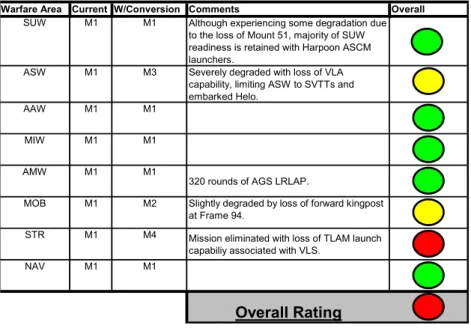
The war-fighting capabilities of USS THORN, modified as described above, are analyzed via a SORTS-based M-rating. Table 3 shows the ratings of each of the major warfare areas for USS THORN. The effect of adding the Advanced Gun System is not factored into this rating, since each of the alternatives involves installing the AGS and hence would alter each variant’s M-rating equally. Each system removed to facilitate the AGS installation is modeled as “not operational,” affecting the overall capabilities retained for that warfare area. The standard Navy reporting procedures are used. In this system, a rating of M-1 is represented as green. A rating of M-2 or M-3 is represented as yellow, or degraded. A rating of M-4 is represented as red, indicating that no significant capabilities are retained in that area. The overall rating of the ship is based on the lowest rating of any single warfare area.
The loss of the Tomahawk weapon system by removing the VLS automatically degrades the strike warfare readiness to a minimum. In addition, the loss of the VLS eliminates the Vertical Launch ASROC (VLA) from the ship’s arsenal. Removing VLA capabilities degrades the anti-submarine warfare (ASW)
readiness significantly, leaving only over-the-side Surface Vessel Torpedo Tubes (SVTTs) and the embarked LAMPS III helicopter for anti-submarine weapons. Further, this arrangement eliminates the forward retractable kingpost near frame 94, degrading the ship’s mobility (MOB) rating. Since ASW is a major warfare focus of the Spruance-class destroyers, the degradation in this area is significant. By eliminating an entire warfare area and degrading a major focus of the platform’s capabilities, this conversion option significantly degrades the versatility of the ship system as a whole.
Warfare Area Current W/Conversion Comments Overall
SUW M1 M1 Although experiencing some degradation due to the loss of Mount 51, majority of SUW readiness is retained with Harpoon ASCM launchers.
ASW M1 M3 Severely degraded with loss of VLA capability, limiting ASW to SVTTs and embarked Helo.
AAW M1 M1
MIW M1 M1
AMW M1 M1
320 rounds of AGS LRLAP.
MOB M1 M2 Slightly degraded by loss of forward kingpost at Frame 94.
STR M1 M4 Mission eliminated with loss of TLAM launch capabiliy associated with VLS.
NAV M1 M1
Overall Rating
Table 3 -- Option 1 - Mount 61 forward, replacing MT51 and VLS This readiness comparison is prepared using Ships Operational Readiness and Training System (SORTS) guidelines establishing material readiness levels WRT warfare area. The warfare areas included are: SUW - Surface Warfare, ASW - Anti-Submarine Warfare, AAW - Anti-Air Warfare, MIW - Mine Warfare, AMW - Amphibious Warfare, MOB - Mobility, STR - Strike Warfare, NAV - Navigation and Safety. The overall M-Rating is color coded with the accepted USN method for brief reporting of readiness: RED -- M-4,
3.1.2 – WEIGHT AND STABILITY ANALYSIS
The displacement of USS THORN as a result of this conversion is reduced by approximately 156LT. Table 4 shows a summary of the weight additions and losses used to balance the new ship arrangement. The weight added includes the total gun system weight, the weight of the structural components necessary to rebuild the decks in the area of the removed VLS space, and 40 pallets (8 binary rounds per pallet) of ammunition in the magazine spaces. The details of the individual component weights and centers used to develop this balance are presented in Appendix B in the form of an accounting spreadsheet tracking each component of the overall AGS system. The weight removed includes all components and the magazine contents of the forward 5in/54 caliber gun mount (Mount 51). In addition, the components and missiles of the VLS and Tomahawk systems are subtracted from the ship’s displacement.
As a result of the above-mentioned weight accounting, the total displacement of USS THORN is reduced by 156LT, to approximately 8585LT total. The ship’s mean draft is therefore reduced by approximately 3 inches, as determined from the ship’s curves of form. The resulting change in trim will be approximately 1.32 feet by the stern. Therefore, if the ship normally trims on an even keel, the converted ship will trim by the stern. This change in trim can be reduced by removing a portion of the 153.6LT of ballast added to the aft portion of the ship as part of the VLS installation modifications. Therefore, no major weight or stability issues are introduced as a result of this conversion installation option.
Component Weight (LT) VCG LCG AGS Gun Assembly 78.64 49.5 187.2 Ammo Handling System 128.34 25 170.5
Cooling Skid 1.29 18 170.5
Core Gun System 208.27 34.21 176.81
Deck-over VLS 30 33.21 159.78
Ammo 100.00 33.6 171.3
338.27 33.94 173.67
MT 51 Drum & Foundation 2.24 42.37 195.08 MT 51 Gun Assembly 22.35 50.16 194.92
5in Ammo 28.08 22.22 187.91
5in/54cal Gun System 52.67 34.93 191.19
VLS & TWCS Systems 275.56 29.92 150.77
Missiles 165.9 32.96 152.74
VLS Missile Assy. 441.46 31.06 151.51
494.13 31.47 155.74
Baseline Displacement 8741 LTON
Altered Disp. 8585.14 LTON
Baseline Draft 20.5 ft TPI 51.55 LTON/in Altered Draft 20.25 ft LCG -42.5 ft MT1" 1565 ft-LTON Change in Draft -0.25 ft Change in Trim 15.87 in 1.32 ft ADDED WEIGHTS REMOVED WEIGHTS TOTAL ADDED
Table 4 -- Option 1 - Mount 61 forward, replacing MT51 and VLS
116.83 TOTAL REMOVED
TOTAL CHANGE IN WEIGHTS -155.86 26.13 CHANGE IN TRIM
By the Stern
3.2 – OPTION 2: AFT MOUNT AT FRAME 440 WITH STANDARD MAGAZINE
The second option explored involves removing the aft 5in/54 caliber gun mount, its associated equipment and magazines, as well as removing the NATO Sea Sparrow Missile System (NSSMS). The AGS mount is placed on the O-1 level at frame 440, where the NSSM launcher is removed. The aft 5in/54 caliber gun mount is removed and decked over, and the spaces immediately below the mount are used as magazines. The fantail can be used as a vertical replenishment location for reload of the AGS magazines. Removing these two major systems provides the necessary space and weight allowance for a magazine of 304 rounds.
Again, this magazine is divided into four compartments to maintain transverse watertight bulkheads for floodable length considerations. The resulting magazine arrangement occupies the main deck between frame 426 and frame 464, the first platform between frame 426 and frame 506, and the second platform between frame 464 and frame 506, with a watertight bulkhead retained at frame 464. A two-level primary magazine exists under the AGS mount between frame 426 and frame 464. This primary magazine resides on the main deck and the first platform; the load drum assemblies (port and starboard) extend down into the second platform space directly below the gun at frame 440. A secondary magazine occupies the space between frame 464 and frame 506 on the first and second platforms. To move ammunition between the two magazines, the existing ammunition elevator is retained just aft of frame 464 to transport ammunition from the aft magazine to the main deck level, where the ammunition can be loaded into the AGS mount. The deck layouts for the main deck, first platform, and second platform between frame 426 and frame 506 are shown in Appendix C.
3.2.1 – WAR-FIGHTING CAPABILITIES ASSESSMENT
The war-fighting capabilities of USS THORN, modified as described above, are analyzed via a SORTS-based M-rating in Table 5. Again, the effect of adding the Advanced Gun System itself is not factored into this rating, since each of the alternatives involves installing the AGS. Each system removed to facilitate the AGS installation is modeled as “not operational,” affecting the overall capabilities retained for that warfare area.
The removal of the NSSM system degrades the anti-air unit self defense area by eliminating one of the mid-range self-defense weapons. USS THORN still retains the Rolling Airframe Missile (RAM) system, but does experience a degradation of the total air-warfare self-defense system. This degradation can be eliminated with the integration of the Enhanced NATO Sea Sparrow Missile System (ENSSMS), which utilizes the existing NSSMS RADAR and fire control equipment, and launches Sea Sparrow missiles from the VLS. All other warfare areas are retained and fully capable with this arrangement, including all elements of the ASW suite. Therefore, there is only a minor degradation of the overall war-fighting capabilities of the ship as a result of this conversion option. There is, however, slight degradation to the area of mobility (MOB). This configuration necessitates removal of the aft kingpost, near frame 434, reducing the connected replenishment capabilities of the ship.
Warfare Area Current W/Conversion Comments Overall
SUW M1 M1 Although experiencing some degradation due to the loss of Mount 52, majority of SUW readiness is retained with Harpoon ASCM launchers.
ASW M1 M1
AAW M1 M3/M1 Potential degradation of unit self defense with elimination of NSSMS can be corrected with ESSMS in VLS.
MIW M1 M1
AMW M1 M1 304 rounds of AGS LRLAP.
MOB M1 M2 Slightly degraded by loss of aft kingpost at Frame 434.
STR M1 M1
NAV M1 M1
Overall Rating
Table 5 -- Option 2 - Mount 62 replacing MT52 and NSSM This readiness comparison is prepared using Ships Operational Readiness and Training System (SORTS) guidelines establishing material readiness levels WRT warfare area. The warfare areas included are: SUW - Surface Warfare, ASW - Anti-Submarine Warfare, AAW - Anti-Air Warfare, MIW - Mine Warfare, AMW - Amphibious Warfare, MOB - Mobility, STR - Strike Warfare, NAV - Navigation and Safety. The overall M-Rating is color coded with the accepted USN method for brief reporting of readiness: RED -- M-4, YELLOW -- M-2 or 3, GREEN -- M-1.
3.2.2 – WEIGHT AND STABILITY ANALYSIS
The displacement of USS THORN as a result of this conversion is increased by approximately 237LT. Table 6 shows a summary of the weight additions and subtractions used to balance the new ship arrangement. The weight added is composed of the total gun system weight and the weight of the 38 pallets (8 binary rounds per pallet) of ammunition in the magazine spaces. The details of the individual component weights and centers used to develop this balance are presented in Appendix C in the form of an accounting spreadsheet tracking each component of the overall AGS system. The weight removed
includes all components and the magazine contents of the aft 5in/54 caliber gun mount (Mount 52). In addition, the launcher components and missiles for the NSSM system are subtracted from the ship’s displacement. The NSSMS RADAR illuminators and fire control equipment are retained to facilitate the possible future integration of ENSSMS.
As a result of the above-mentioned weight accounting, the total displacement of USS THORN is increased by 237LT to approximately 8978LT total. The ship’s mean draft is therefore increased by approximately 4.6 inches. The resulting change in trim will be 1.93 feet by the stern. Therefore, if the ship normally trims on an even keel, the converted ship will trim by the stern. Again, this change in trim can be reduced by removing a portion of the 153.6LT of ballast added to the aft portion of the ship as part of the VLS installation modifications. Therefore, no major weight or stability issues are introduced as a result of this conversion installation.
Component Weight (LT) VCG LCG
AGS Gun Assembly 78.64 46 -185.5 Ammo Handling System 129.54 24.75 -198.5
Cooling Skid 1.29 18 -211.5
Core Gun System 209.47 32.69 -193.70
Ammo 95.00 24.75 -209.6
304.47 30.21 -198.66
MT 52 Drum & Foundation 2.24 30.4 -223.92 MT 52 Gun Assembly 22.35 37.27 -223.92
5in Ammo 27.47 20.43 -226.89
5in/54cal Gun System 52.06 28.09 -225.49
Launcher Assy. 4.45 46 -185.5
Missiles in Launcher Assy. 1.61 48 -185.5 Missiles in Mag. 9.09 44.93 -143.8
NSSMS Assy. 15.15 45.57 -160.48
67.21 32.03 -210.83
Baseline Displacement 8741 LTON Altered Disp. 8978.26 LTON
Baseline Draft 20.5 ft TPI 51.55 LTON/in Altered Draft 20.88 ft LCG -42.5 ft MT1" 1565 ft-LTON Change in Draft 0.38 ft Change in Trim 23.15 in 1.93 ft
Table 6 -- Option 2 - Mount 61 aft, replacing MT52 and NSSM
-195.21 TOTAL REMOVED
TOTAL CHANGE IN WEIGHTS 237.26 29.69 ADDED WEIGHTS
REMOVED WEIGHTS TOTAL ADDED
CHANGE IN TRIM
By the Stern
3.3 – OPTION 3: AFT MOUNT AT FRAME 440 WITH EXTENDED MAGAZINE
The third option explored is an extension of the second option described above in section 3.2. The AGS mount and magazine installations are identical, but an additional magazine space is included on the main deck in a new “shed” structure covering the original Mount 52 area. The AGS mount is still placed on the O-1 level at frame 440, where the NSSM launcher is removed. The aft 5in/54 caliber gun mount is removed, decked over, and a 22ft wide housing is built extending the O-1 level weather deck to frame 506. The spaces immediately below the mount are also used as magazines. The extension of the main deck allows an additional 12 pallets of binary rounds, increasing the total magazine capacity to 50 pallets
or 400 rounds. The deck layout for the main deck between frame 426 and frame 506 is shown in
Appendix D. The first and second platform arrangements are identical to those shown in Appendix C
for the second conversion option.
3.3.1 – WAR-FIGHTING CAPABILITIES ASSESSMENT
The warfare capabilities of USS THORN in this arrangement are identical to those of the arrangement presented in section 3.2 except that the AGS has enhanced capabilities due to the extended magazine capacity. Since the war fighting enhancements due to the AGS are not considered for this report, the resulting M-rating for this arrangement is identical to that for the second configuration described. This rating analysis is shown in Table 7. There is only a minor degradation of the overall war-fighting capabilities of the ship as a result of this conversion option
Warfare Area Current W/Conversion Comments Overall
SUW M1 M1 Although experiencing some degradation due to the loss of Mount 52, majority of SUW readiness is retained with Harpoon ASCM launchers.
ASW M1 M1
AAW M1 M3/M1 Potential degradation of unit self defense with elimination of NSSMS can be corrected with ESSMS in VLS.
MIW M1 M1
AMW M1 M1 400 rounds of AGS LRLAP.
MOB M1 M2 Slightly degraded by loss of aft kingpost at Frame 434.
STR M1 M1
NAV M1 M1
Overall Rating
Table 7 -- Option 3 - Mount 62 aft with extended magazine This readiness comparison is prepared using Ships Operational Readiness and Training System (SORTS) guidelines establishing materiel readiness levels WRT warfare area. The warfare areas included are: SUW - Surface Warfare, ASW - Anti-Submarine Warfare, AAW - Anti-Air Warfare, MIW - Mine Warfare, AMW - Amphibious Warfare, MOB - Mobility, STR - Strike Warfare, NAV - Navigation and Safety. The overall M-Rating is color coded with the accepted USN method for brief reporting of readiness: RED -- M-4, YELLOW -- M-2 or 3, GREEN -- M-1.
3.3.2 – WEIGHT AND STABILITY ANALYSIS
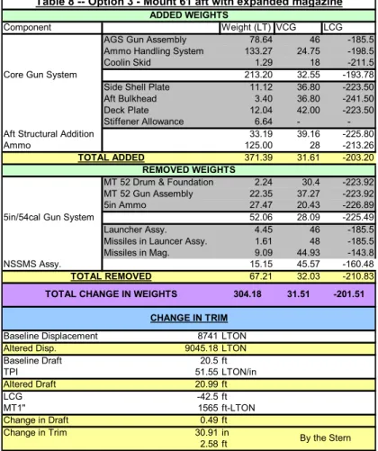
The displacement of USS THORN as a result of this conversion is increased by approximately 303LT. Table 8 shows a summary of the weight additions and subtractions used to balance the new ship arrangement. The weight added is similar to that shown in section 3.2, but also includes the structural components of the main deck extension constructed for the expanded magazine. The details of the individual component weights and centers used to develop this balance are presented in Appendix D in the form of an accounting spreadsheet tracking each component of the overall AGS system. The removed weight is identical to the weight accounting for option two.
As a result of the above-mentioned weight accounting, the total displacement of USS THORN is increased by 303LT to approximately 9044LT total. The ship’s mean draft is therefore increased by approximately 6 inches. The resulting change in trim will be 2.58 feet by the stern. This trim is slightly more than can be corrected by removing the 153.6LT of ballast added to the aft portion of the ship as part of the VLS installation modifications. The significant weight increase, due to the 12 additional
pallets of ammunition and the added “shed” structure, and the trim issues introduced limit the feasibility of this option.
Component Weight (LT) VCG LCG
AGS Gun Assembly 78.64 46 -185.5 Ammo Handling System 133.27 24.75 -198.5 Coolin Skid 1.29 18 -211.5 Core Gun System 213.20 32.55 -193.78 Side Shell Plate 11.12 36.80 -223.50 Aft Bulkhead 3.40 36.80 -241.50 Deck Plate 12.04 42.00 -223.50 Stiffener Allowance 6.64 - -Aft Structural Addition 33.19 39.16 -225.80
Ammo 125.00 28 -213.26
371.39 31.61 -203.20 MT 52 Drum & Foundation 2.24 30.4 -223.92 MT 52 Gun Assembly 22.35 37.27 -223.92 5in Ammo 27.47 20.43 -226.89 5in/54cal Gun System 52.06 28.09 -225.49 Launcher Assy. 4.45 46 -185.5 Missiles in Launcer Assy. 1.61 48 -185.5 Missiles in Mag. 9.09 44.93 -143.8
NSSMS Assy. 15.15 45.57 -160.48
67.21 32.03 -210.83
Baseline Displacement 8741 LTON Altered Disp. 9045.18 LTON Baseline Draft 20.5 ft TPI 51.55 LTON/in Altered Draft 20.99 ft LCG -42.5 ft MT1" 1565 ft-LTON Change in Draft 0.49 ft Change in Trim 30.91 in 2.58 ft By the Stern CHANGE IN TRIM -201.51 TOTAL REMOVED
TOTAL CHANGE IN WEIGHTS 304.18 31.51 ADDED WEIGHTS
REMOVED WEIGHTS TOTAL ADDED
Table 8 -- Option 3 - Mount 61 aft with expanded magazine
3.4 – FINAL BASELINE CONCEPT DESIGN
From the results of the trade-off studies conducted, option two, the aft AGS mount alternative with the 304 round magazine was chosen as the “best” alternative for this application due to the retention of more major war-fighting capabilities while minimizing cost and impact on the ship and its crew. The forward mount alternative (option 1) was eliminated due to the loss of the Vertical Launch System. Retaining the VLS is a very attractive proposition to maintain a well-rounded war-fighting platform. The aft mount with the extended magazine (option 3) is shown to lead to both weight and trim concerns.
In addition, the relative costs of the three options must be considered. All three options involve the installation of the gun, the rails and automated magazine systems, and at least one ammunition strike-down elevator. The first option would include the construction costs for re-building the decks in the former VLS space. It also requires the installation of two strike-down elevators, one on either side of the transverse watertight bulkhead separating the magazine spaces.
Both of the aft options only require one additional strike-down elevator to be built since the existing elevator just aft of frame 464 can be re-used for moving ammunition between the secondary magazine and the gun mount. The third option involves the additional construction costs of building the main
deck extension for the expanded magazine. Therefore, from a qualitative perspective, the second option is also the lowest cost option, in alignment with the stated design philosophy.
For warfare capability, feasibility, and cost considerations, the second option is identified as the “best” option of those analyzed. Further details of the arrangements, system interfaces, and behaviors of the converted ship for this option are presented in Chapter 4 of this report.
4.0 – FEAS IB ILITY STUDY AN D ASS ES S MEN T 4.1 – DESIGN DEFINITION
The chosen design alternative from Chapter 3 was used to complete a more detailed, feasibility-level study of the installation of the AGS on USS THORN. Assessment of the structural integrity, stability characteristics, electrical and auxiliary system impacts, and overall arrangement modifications of the converted ship were completed and are described below.
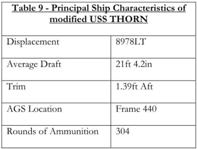
4.1.1 – PRINCIPAL SHIP CHARACTERISTICS SUMMARY
Although the modified USS THORN remains essentially similar in principal characteristics to a baseline Spruance-class destroyer, the major differences are listed in Table 9. There is a slight increase in both displacement and draft as a result of the conversion. In addition, a small trim by the stern is introduced, that can be corrected with the removal of lead ballast in the aft portion of the ship. The most obvious modification to the platform is the addition of the AGS mount and its ammunition.
Table 9 - Principal Ship Characteristics of modified USS THORN
Displacement 8978LT Average Draft 21ft 4.2in
Trim 1.39ft Aft
AGS Location Frame 440
Rounds of Ammunition 304
4.1.2 – ARRANGEMENT
The placement of the AGS on USS THORN was accomplished with a conscious effort to minimize the impact on the existing ship's arrangement. In this manner, transverse watertight bulkheads are unaltered, and existing deck layouts are used (with slight modifications) to the greatest extent possible. Additionally, the existing aft 5-inch ammunition-handling elevator is retained for use in the automated ammunition handling system of the AGS.
4.1.2.1 – Mission Payload/Layout
The AGS trunion ring and mount are installed in the modified USS THORN at frame 440. In this location, the AGS mount replaces the existing NATO Sea Sparrow Missile (NSSM) launcher. The associated ammunition magazine and automated ammunition handling system extend below decks into five watertight compartments:
1. 1-426-0 - displacing the Deck Gear Storeroom #3 434-0), the NSSMS Equipment Room (1-448-0), and the aft connected replenishment (CONREP) kingpost.
2. 2-426-0 - displacing the Flammable Liquids Storeroom (2-426-0), and the Physical Fitness Room (2-436-0).
3. 2-464-0 - displacing the Ship's Stores Room (2-464-01), the Mount 52 Loader Drum (2-482-0), the Crew Baggage Storeroom (2-494-1), and the Hobby Shop (2-494-0).
4. 3-426-0 - displacing the Ship's Clothing Storeroom and Issue (3-426-0) and the Chemical Warfare Storeroom (3-446-0).
5. 3-464-0 - displacing the Mount 52 Ammunition Pallet Staging Room (3-464-01), the Mount 52 5in. Projectile Magazine (3-482-0), and the Mount 52 Powder Magazine (3-494-0).
Many of the spaces displaced by the installation of the AGS ammunition handling system and magazine are no longer necessary as a result of the conversion and have no impact on the overall arrangement of the modified USS THORN. These include the spaces associated with the NSSMS and Mount 52. Other spaces can be absorbed into other existing spaces elsewhere in the ship. For example, the Flammable Liquids Storeroom can be combined with the Paint Mixing and Issue room to consolidate the two functions in the modified ship.
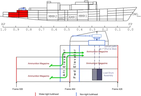
4.1.2.2 – Inboard Profile
The placement of the AGS on USS THORN is illustrated in Figure 1. The location of the AGS and its associated magazine and ammunition handling spaces are highlighted in the top portion of the figure. A detailed diagram of the ammunition magazine, automated ammunition handling system and ammunition pallet transfer path between the two magazine sections is provided in the lower portion of Figure 1.
AMR2 AMR1 MMR1
MMR2 DWL
1.0 0.9 0.8 0.7 0.6 0.5 0.4 0.3 0.2 0.1 0.0
AP FP
Frame 506 Frame 464 Frame 426 Water-tight bulkhead Non-tight bulkhead
Load Drum Assembly Upload paths (Port & Stbd) Af t E lev a to r Fw d E le v a t o r Ammunition Magazine Ammunition Magazine Ammunition Magazine Ammunition Magazine
Figure 1 -- Inboard Profile and Ammunition Flow Path
4.1.2.3 – Deck Plans
The detailed arrangements of the five below-decks AGS spaces, including the ammunition handling track and the ammunition pallet layouts, are included in Figures 2, 3, and 4. Figure 2 shows the
arrangement of the main deck, including the locations of both ammunition strike-down elevators. The download and upload hoists of the AGS mount are delineated by the rectangular-shaped area at frame 440. The bulkhead at frame 464 (represented by the dashed line) is non-tight, containing the pass-through doors between the two ammunition strike-down elevators. With this pass-pass-through design, both the primary and the secondary ammunition magazines may be re-loaded from the vertical replenishment area on the main deck where Mount 52 was removed. The elevator aft of frame 464 is also used to hoist ammunition from the aft magazines on the first and second platforms (shown in Figures 3 and 4) to the main deck for use in the AGS.
0 50 FT SCALE FR 464 FR 426 EL EL FR 440 Chemical Warfare Equipment Storeroom
Inert Gas and
Spare CO2 Cylinder Storeroom Paint Mixing and Issue Room
Figure 2 -- Main Deck Magazine Layout
Figure 3 shows the magazine arrangements on the first platform. The magazine space forward of the transverse watertight bulkhead at frame 464 is automated to allow direct ammunition loading into the AGS upload paths. Ammunition pallets from the aft magazines are loaded into the aft elevator, hoisted to the main deck, and enter the upload path from the pass-through at frame 464.
0 SCALE 50ft EL FR 464 FR 506 FR 426 EL
Figure 3 -- First Platform Magazine Layout
Figure 4 shows the magazine arrangements on the second platform. The aft magazine continues onto this level aft of frame 464. Again, ammunition pallets from this magazine are hoisted to the main
deck for entry into the AGS upload path. The two load drum assemblies reside on the second platform forward of frame 464. These ram assemblies receive the ammunition from the magazines and upload the rounds to the gun mount. Two assemblies exist, one port and one starboard, to facilitate clear passage down the centerline of each magazine level for the automated ammunition handling carts.
SCALE OMR1 0 50 FT EL FR 464 FR 426 FR 506
Figure 4 -- Second Platform Magazine Layout
4.1.3 –ELECTRICAL AND AUXILIARIES
4.1.3.1 – Electrical Power and Distribution
Since much of the AGS system is still in the development stages, the electrical powering requirements of the system can only be approximately estimated. The manufacturers of the gun system estimate that the peak load of the system in operation will be approximately 800kW. Hence, the electrical load analysis of installing the AGS on USS THORN is based on this estimate.
Further, there are many possible power distribution configurations with respect to the AGS that will require further development by the gun system manufacturer. For purposes of this feasibility study, the AGS was analyzed with a direct feed of shipboard 450V(AC), 60Hz, 3-phase power. To determine the existing electrical load of USS THORN, two sources were consulted: the Joint NGSS/UDLP feasibility study and the Chief Engineer of USS THORN. In light of the uncertainty regarding the AGS required loads, the more conservative of the two electrical loads was used for the purposes of this analysis.
The maximum generation capacity of USS THORN is 3600kW, 90% of two paralleled 2000kW generators with a third 2000kW generator as a backup. All loads, either added or removed, including the AGS system, were calculated for battle conditions on a 10º-Celsius day using a battle demand factor. A 10º-Celsius day represents the worst case loading for the generation system.
Table 10 represents the electrical load analysis of the modified USS THORN. The most conservative baseline battle condition load was taken to be 2743kW, and the final electrical load of the modified USS THORN was estimated to be 3462kW. This altered load can be accommodated by the current electrical generation system, but at a drastic reduction in the electrical load margin.
Component Cruise Load (kW) Core Gun System 800
TOTAL ADDED 800
5in/54cal Gun System 36.6 NSSMS Missile Assy. 31.1 TOTAL REMOVED 67.7 Generation Capacity Baseline Load Altered Load Baseline Electrical Load Margin
Altered Electrical Load Margin
ADDED ELECTRICAL LOADS
50.2 31.1
Table 10 -- Electrical Load Breakdown
81.3 Battle Load (kW)
800 800
REMOVED ELECTRICAL LOADS
TOTAL CHANGE IN
ELECTRICAL LOAD 732 719
ELECTRICAL LOAD DETAILS
138 3600 2743 3462 857
With this reduced electrical load margin in mind, the recommended power distribution configuration of the AGS is illustrated in Figure 5. This configuration requires the installation of one 400A breaker on L/C 31 and one 800A breaker on 2SB for primary power and one 400A and 800A breaker on L/C 42 for back-up power. Such a configuration makes it possible to split the ship’s electrical plant. A majority of ship’s systems can then be powered from generators one and three on the forward bus, and the AGS can be isolated on the aft bus, powered by number two generator. Such a configuration may provide the most stable power conditions.
2SA (1) 400A A B T 2S 2SB (1) 400A 1SB 1 Blnk 1600 1S 1SA (1) 400A 3SA 1 Blnk 1600 3S 3SB 2SG 3SG 1SG L/C 31 L/C 12 (1) 800 A L/C 41 (1) 400A L/C 11 (1) 800A L/C 42 (1) 400A A B T New 1600 A 450 Vac 3Ø, 800 Ampere 450 Vac 3Ø, 400 Ampere 1S Normal/ 2S Alternate 3S Normal/ 1S Alternate AGS Gun Mount AGS Gun Magazine
Figure 5 -- Electrical Distribution Connections
4.1.3.2 – Fire Main
USS THORN fire main system consists of six electrically driven fire pumps, supplying seawater through risers to a primary main located on the damage control deck. Each pump is capable of supplying 1100gpm of seawater to the fire main at 150psi. The main distribution loop is capable of being segregated
into three independent sections, each serviced by two pumps. Under normal operations, the segregation points are opened to form a single main loop. Seawater is supplied to damage control equipment and other systems from this primary loop.
Component Flow (gpm) AGS Mag. Sprinkling 3947 AGS Secondary Cooling 285
TOTAL ADDED 4232
5in/54cal Projectile Mag 280 5in/54cal Powder Mag 150 5in/54cal Loader Drum Room 561 5in/54cal Pallet Staging Room 353 NSSMS Missile Mag. 450
TOTAL REMOVED 1794
Table 11 -- Fire Main System Requirements
REMOVED FIRE MAIN REQUIREMENTS
2438 TOTAL CHANGE IN FIRE MAIN
REQUIREMENTS
ADDED FIRE MAIN REQUIREMENTS
The AGS requires magazine sprinkling for fire suppression. Table 11 illustrates the impact of the AGS installation on the fire main system of the modified USS THORN. Although the existing equipment can accommodate this large net increase in demand on the fire main system in a single loop configuration, it represents a large increase in demand on the two fire pumps associated with the aft fire main section in the segregated loop configuration. Therefore, in the event of a magazine sprinkler light-off, the main fire main loop must be opened to provide adequate flow and pressure throughout the system. This doctrine change should be incorporated into the ship’s damage control procedures to prevent system failure.
4.1.3.3 – Chilled Water
USS THORN’s chilled water system consists of three 150-ton air conditioning plants, three expansion tanks, three 540gpm chilled water pumps, and the associated supply and return piping to vital and non-vital users. Air conditioning plants numbers 1 and 2, along with their associated pumps and expansion tanks, are located in Auxiliary Machinery Room No. 1 (5-220-0-E). Air conditioning plant number 3 is located in Pump Room No. 2 and Air Conditioning and Chilled Water Machinery Room (3-398-0-Q). Each air conditioning plant is operated as an independent plant with a cross-connect capability. The air conditioning plants make use of a centrifugal-type compressor to supply chilled water at approximately 44 degrees F to fan coils, cooling coils, gravity coils, electronic cooling water heat exchangers, hydraulic oil coolers, and condenser filters.
Component Flow (gpm) AGS Assy. 88
TOTAL ADDED 88
5in/54cal Projectile Mag 2 5in/54cal Powder Mag 1.5 5in/54cal Loader Drum Room 45 NSSMS Missile Mag. 3
TOTAL REMOVED 51.5
Table 12 -- Chilled Water System Requirements
REMOVED CHILLED WATER REQUIREMENTS
37 TOTAL CHANGE IN CHILLED WATER
REQUIREMENTS
Installation of the AGS on the modified USS THORN would have a large impact on the chilled water system. Table 12 shows the overall impact of AGS on the chilled water system. The additional draw on the chilled water system is within the capacity of the installed system. Strenuous conditions such as extreme warm weather operations will require close monitoring of the chilled water system to ensure proper operations.
4.1.4 – STRUCTURAL DESIGN
The structural arrangement of the modified USS THORN remains identical to the baseline configuration. Since the details of the ship’s scantlings are classified, a representative amidships section was used to model USS THORN using the POSSE program for structural analysis. Through a detailed analysis of the bending moments produced at the amidships section, the existing design is seen to be sufficient to accommodate the inclusion of the AGS on USS THORN. While it is believed that the model constructed in POSSE is close to the actual ship conditions, there is some amount of uncertainty with this analysis. Since the model in POSSE was believed to be approximately correct, all analysis performed in POSSE was completed using the original, unmodified model before the AGS installation. The analysis was then repeated for the modified models for all cases studied so that relative changes could be determined.
4.1.4.1 – Strength Curves
Through a comparison of the structural characteristics of the modified USS THORN with the baseline configuration, the bending moments are seen to change insignificantly, well within the structural limits of the ship. Detailed computations can be seen in Appendix E.
4.1.5 – WEIGHTS, STABILITY AND MARGINS
Since the exact weights and weight distribution of the Navy’s POSSE files for USS THORN are classified, a representative POSSE model of the ship’s weight and distribution was determined from unclassified sources. These sources include ASSET program “match runs” from the original Spruance-class baseline ship and the CG-52 Ticonderoga Spruance-class cruiser, and, most influentially, the actual draft of USS THORN. The combination of this information yielded a POSSE modeled full load displacement of USS THORN at approximately 8741LT. From this model, POSSE was used to add point loads for the AGS modification. Minimum operating conditions were also modeled per the specifications of DDS 079-1. In POSSE the seawater-compensated fuel tanks at the minimum operating condition were modeled as full with a liquid having a specific gravity weighted for 1/3 fuel and 2/3 seawater. While it is believed that the model constructed in POSSE is close to the actual ship conditions, there is some amount of uncertainty with this analysis. Since the model in POSSE was believed to be approximately correct, all analysis performed in POSSE was completed using the original, unmodified model before the AGS installation. The analysis was then repeated for the modified models for all cases studied so that relative changes could be determined.
4.1.5.1 – Full Load
As detailed in Appendix F, the full load displacement of the modified USS THORN is approximately 8977LT, a net change of 236LT.
4.1.5.1.1 – Weight Summary
Appendix C summarizes the added weights associated with the AGS as well as the removed weights of the corresponding displaced systems. This change in displacement and weight distribution results in a change in draft of approximately 2.8in and a change in trim of 1.93ft The resulting trim is approximately 1.93ft by the stern.
4.1.5.1.2 – Intact and Damaged Stability
As shown in Appendix F, the intact and damaged stability of the modified USS THORN is essentially unchanged from the baseline configuration. All requirements delineated in DDS 079-1 are met.
4.1.7.2 – Minimum Operating
As detailed in Appendix F, the minimum operating displacement of the modified USS THORN is 8916LT, a net change of -61LT from the full load case, and 175LT greater than the baseline displacement.
4.1.5.2.1 – Weight Summary
Appendix F summarizes the change in weights associated with the minimum operating condition. This change in displacement and weight distribution results in a change in draft of approximately –2in from the full load condition, a change of less than 1in from the baseline condition, and a change in trim of .72ft by the stern from the full load condition, to become 2.11ft by the stern.
4.1.5.2.2 – Intact and Damaged Stability
As shown in Appendix F, the intact and damaged stability of the modified USS THORN is essentially unchanged from the baseline configuration. All requirements delineated in DDS 079-1 are met.
4.1.6 – SURVIVABILITY
By retaining the configuration of watertight transverse bulkheads in the region of the AGS and magazine it can be seen that the modified USS THORN meets damage and flooding requirements in accordance with DDS 079-1. Figure 6 displays the floodable length curve of the modified USS THORN. As the figure shows, 15% of the length of the ship may be damaged without crossing the 75% permeability curve.