HAL Id: hal-00415724
https://hal.archives-ouvertes.fr/hal-00415724
Submitted on 17 Sep 2009
HAL is a multi-disciplinary open access
archive for the deposit and dissemination of
sci-entific research documents, whether they are
pub-lished or not. The documents may come from
teaching and research institutions in France or
abroad, or from public or private research centers.
L’archive ouverte pluridisciplinaire HAL, est
destinée au dépôt et à la diffusion de documents
scientifiques de niveau recherche, publiés ou non,
émanant des établissements d’enseignement et de
recherche français ou étrangers, des laboratoires
publics ou privés.
Molecular engineering to improve the charge carrier
balance in single-layer silole-based OLEDs
Laurent Aubouy, Nolwenn Huby, Lionel Hirsch, Arie van der Lee, Philippe
Gerbier
To cite this version:
Laurent Aubouy, Nolwenn Huby, Lionel Hirsch, Arie van der Lee, Philippe Gerbier. Molecular
en-gineering to improve the charge carrier balance in single-layer silole-based OLEDs. New Journal of
Chemistry, Royal Society of Chemistry, 2009, 33, pp.1290. �10.1039/b900780f�. �hal-00415724�
Molecular engineering to improve the balance of charge carrier in
single-layer silole-based OLEDs.
Laurent Aubouy,
aNolwenn Huby,
bLionel Hirsch,*
bArie van der Lee,
cand Philippe Gerbier*
a5
We report a molecular engineering study on optical, structural and electrical properties of seven silole derivates aiming at enhancing the balance of charge carrier in single-layer devices. By functionalizing two hole-transporting groups, dipyridylamine or anthracene, on the silole ring, we have investigated the influence of both entity types on the hole current. We have concluded that in contrast to dipyridylamine groups, anthracene groups decrease the balance of charge carrier since
10
the latter groups not only increase the hole current but also electron contribution. Doubling the number of hole transporting groups lead the silole D to become a very efficient emissive layer exhibiting threshold voltage below 3 V and luminous efficiency Le = 0.8 cd/A at 7 V.
Introduction
15
Organic light-emitting diodes (OLEDs) using small molecules or polymers have been intensively pursued after the initial works by Tang, Van Slyke and Burroughes1, 2 because
of their enormous potential in flat, flexible panels lighting and displays. The search for efficient and stable new emitting
20
materials with appropriate emission spectrum remains as one of the most active areas of these studies. Different strategies have been developed to enhance the efficiency of the devices such as the assisted singlet-triplet internal conversion and the balance of charge carriers in the emissive zone. Among them,
25
the approach involving the incorporation of heavy metal complexes has attracted a great attention since it allows to obtain both very high efficiencies and white emission.3-8 On
the other hand, the balance of charge carriers in the emissive zone has attracted much less attention due to the development
30
of multilayer structures as a response to this issue.9, 10 Indeed,
in organic semi-conductors, one of both charge-carriers presents a higher mobility compared to the other one. This leads to several drawbacks such as, for instance, the location of the recombination zone close to an electrode, leading to a
35
huge quenching of excitons. Therefore it is possible to overcome this problem by using PIN OLEDs structures11.
Nevertheless, this approach suffers of some drawbacks due to a large number of interfaces and/or segregation phase apparition.The main text of the article should appear here.
40
Headings and subheadings should be formatted using the
relevant button from the “Styles” toolbar.
a Université Montpellier 2, Institut Charles Gerhardt de Montpellier –
UMR 5253. CC 007, Place Eugène Bataillon ; 34095 Montpellier cedex 5, France. Fax: (+)33.(0)4.67.14.38.52 ; E-mail: gerbier@univ-montp2.fr
b Université Bordeaux 1, Laboratoire d’Intégration du Matériau au
Système (IMS) – UMR 5218. Ecole Nationale Supèrieure de Chimie et de Physique de Bordeaux, 16, Avenue Pey Berland ; 33607 Pessac Cedex, France. Fax: (+)33.(0)5.40.00.66.31 ; E-mail: lionel.hirsch@ims-bordeaux.fr
c Université Montpellier 2, Institut Européen des Membranes - UMR 5635
CC 047, Place Eugène Bataillon; 34095 Montpellier cedex 5, France. Fax (+)33(0)4.67.14.38.52. E-mail: avderlee@univ-montp2.fr
Si Ph Ph Si Ph Ph Ar Ar Si Ph Ph ClZn ZnCl Ar Br N N N N N N N N N N N N N N N O O i, ii iii A Ar = B C D A' B' 1 2
Scheme 1. Tamao’s synthetic route to 2,5-difunctionnalized siloles: i) 4 equiv. LiNp,
The aim of this paper is to design a fluorescent molecule able to transport both charge carriers. In this way, we
45
focussed on silole derivatives since they appear to possess all the requirements to achieve single-layer OLEDs. The siloles 12-15 or silacyclopentadienes are a group of five-membered
silacycles that possess σ*-π* conjugation arising from the interaction between the σ* orbital of two exocyclic σ bonds
50
on the silicon atom and the π* orbital of the butadiene moiety.16 As a consequence, the calculated LUMO level of a
silole ring is lower than those of other heterocyclopentadienes, such as pyrrole, furan, and thiophene. Moreover, thanks to its nonaromatic character the π-system of
55
the silole ring is more prone to allow electron delocalization when compared with its thiophene cousins.17, 18 From a
structural point of view, because of the non-coplanar structure of 2,3,4,5-tetraarylsiloles, the distances between silole cores of any two adjacent molecules, even in the solid state, are far
60
from the normal π–π interaction distance (ca. 3–4 Å).19 This
gives rise to a very interesting photophysical property called aggregation-induced photoluminescence (PL) emission (AIE).20, 21 Because of the AIE characteristics,
2,3,4,5-tetraphenylsiloles can show extremely high PL quantum
65
yields (up to 100%), even in a crystalline form.22, 23 Thereby,
2,3,4,5-tetraphenylsiloles are excellent emitters in the fabrication of electroluminescence (EL) devices, an external
quantum efficiency (ηEL) up to 8%, close to the theoretical
limit for a singlet emitter, was realized with such derivatives
70
in the emissive layer.24, 25 Finally, siloles exhibit very high
electron mobility, exceeding the well-known tris-(8-hydroxyquinoline) aluminum (Alq3), and have been utilized as the electron-transporting layer for EL devices.26-28
The results presented in this paper follow previous reports
75
concerning the silole A (Scheme 1).25, 27 This molecule is
based on a silacyclopentadiene core, which acts both as emissive and electron-transporting component, and two dipyridylamino functionalities grafted on each side, which act as hole-transporting groups.29, 30 By associating those two
80
functionalities, we have achieved a sufficient balance of charge to make light from single-layer OLEDs. However, the temperature dependence and the electron injection barrier dependence investigations have highlighted the weak hole contribution in hole-only devices that is only three orders of
85
magnitude lower than the electron one.27 Since it may be
expected that a better balance of charge should improve greatly the efficiency of the devices, we have designed the siloles shown in Schemes 1 and 3 with increasing their hole-transporting properties. On the one hand, the dipyridylamino
90
hole-transporting groups were changed by anthracenyl ones that are well known as good hole-transporting group in molecular films (siloles B and B’).31, 32 On the other hand, we
changed the hole-carriers to electron-carriers ratio that is 1:1 for silole E, 2:1 for siloles A, A’, B, B’ and 4:1 for siloles C
95
and D. The effect of the conjugation between electron- and hole-transporting moieties was also studied by inserting a disrupting ether bridge between the two (siloles A vs A’ and B
vs B’). Optical and structural properties are systematically
correlated to the device performances in order to highlight the
100
influence of the number of hole-transporting group on the balance of charge carriers.
Results and Discussion
Br Br Br Br N N N N N N N N NH Br Br O Br O Br Br O Br N N N O Br Br O Br iii 5 i, ii 3 4 6
Scheme 2. Syntheses of the hole-transporting functionalities: i) 1 equiv. nBuLi, ii)
MeOH, HCl 6 M, iii) K2CO3, CuSO4.5H2O.
O O Br N N N O OH N N N OH N N N O H Br N Br N N + i 8 10 ii iii 7 9 Scheme 3. Synthesis of 10: i) nBuLi, ii) 2 equiv. 1-bromo, 4-lithiobenzene, iii)
(i) Syntheses
The siloles A-D were conveniently prepared by the method
105
described by Tamao and Yamaguchi33 that involves the
one-pot reductive intramolecular cyclization of bis(phenylethynyl)silane and the subsequent Pd(0)-catalyzed cross-coupling reaction with the desired arylbromide (Scheme 1). The synthesis of (4-bromophenyl)-anthracene 3 and
9-110
[4-(4-Bromo-phenoxy)-phenyl]anthracene 4 was achieved starting from anthrone by using the procedure described by Murphy et al..34 3,5-bis(2,2’-dipyridylamino)-bromobenzene 5
and [4-(4-bromo-phenoxy)-phenyl]di-pyridyn-2-yl-amine 6 were synthesized through a modification of the original
115
Ullman’s reaction.35, 36 The preparation of the asymmetrically
9,10-diarylanthracene 10 was achieved through an adaptation of the procedure described by Smet et al..37, 38 It involves
firstly the lithiation of the compound 725, 39 followed by the
addition of the resulting lithio derivative on anthraquinone to
120
afford the monoadduct 8 in 43% yield. To this compound, a two-fold excess of 4-bromophenyllithium was added yielding the diol 9. The excess of 4-bromophenyllithium was necessary to react with the OH group present in the monoadduct 8. Reduction of the latter using NaH2PO2 and KI in refluxing
125
acetic acid afforded 10 as a light yellow solid in 20% yield. The synthesis of silole E involves firstly the preparation of the bis-silole derivative 11 through the Tamao-Yamaguchi’s
reaction between the dizincic intermediate 2 and 1.5 equiv. of
130
1,4-dibromobenzene. The bis(bromophenyl)silole 12 which is formed along with 11 is easily isolated by column chromatography and will serve as starting material for other syntheses. The subsequent Suzuki coupling between 11 and the boronic acid derivative 1339 afforded the expected
bis-135
silole E in good yield. (ii) Geometries of siloles
The determination of the conformational preferences of these molecules is of outmost importance for the
140
understanding of their electronic behaviour. Since crystals suitable for a X-ray structure determination could only be obtained for A,40 B,41 and 11, we turned to density functional
theory (DFT) calculations with the B3LYP functional to obtain information about the molecular conformations for the
145
rest of siloles.42 Due to the size of the molecules, geometry
optimizations without symmetry constrains were performed with the 6-31G basis set to the standard convergence criteria as implemented in Gaussian98.43 Such calculations were
followed by single point runs using a 6-31+G* basis to obtain
150
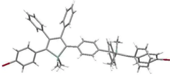
accurate energies. Structurally characterized siloles, dipyridylamines, and diphenylethers served as benchmarks to test how well the experimentally determined geometry is reproduced by the calculations, and some relevant torsion angles are collected in Table 1.19 As exemplified with A
155
(Figure 1), all compounds have a propeller-like arrangement of the four phenyl rings, as found in the crystal structures, while the two methyl substituents on the silicon atom are nearly perpendicular to the mean plane of the SiC4 ring. The
torsion angles of the substituted phenyl rings at the 2- and
5-160
positions of the central silole ring (ϕ1) are in the range of what
is usually observed with tetraarylsiloles (ca. 30-60°).
Si Ph Ph Br Br Si Ph Ph Br Si Br Ph Ph Si Ph Ph Si Ph Ph N N N N N N N B OH OH N N Br Br i + 7 ii, iii iv 2 + 11 12 13 E
Scheme 4. Synthesis of E: i) PdCl2(PPh3)2, ii) 1 equiv. nBuLi, B(OMe)3, iii) H20, NH4Cl, iv) Pd(PPh3)4, K2CO3.
Si
N N
ϕ1 ϕ2 ϕ3
Scheme 5. Location of the torsion angles reported in table 1.
Table 1. Torsion angles [°] in silolesa
Ab Bb C Db,d E
ϕ1[c] 43.4 (44.7) 49.1 (58.4) 38.6 47.8 43.5 (45.1)
ϕ2[c] 45.4 (34.3) --- 46.8 50.8 (50.4) 55.5
ϕ3[c] --- 77.0 (68.5) --- 71.6 (74.2) ---
a Average values. b Values from crystal structures (see text) are between
The torsion angles between the anthracene main plane and the adjacent phenyl ring (ϕ3) fall as well in the range of what
165
is usually observed with related molecules (ca. 70°). This is expected to induce a strong reduction of the conjugation between the electron-transporting silole ring and the lateral hole-transporting groups. The same is expected when an ether bridge is inserted between the two electroactive components
170
since the plain planes of the phenyl ring on both sides of the oxygen atom are nearly perpendicular (see figure 1). Though no crystal suitable for X-ray diffraction were obtained for the bis-silole E, we were able to solve the structure of its precursor 11. This compound crystallizes along with one
175
CH2Cl2 molecule in the C2/c space group. As seen in Figure 2,
the molecule possesses an axis of symmetry that passes through the middle of the central phenyl ring. The torsion angles ϕ1 between this ring and the two adjacent siloles have a
value of 45.14°. As a result, the two silole rings are nearly
180
perpendicular, which contrasts very strongly with the thiophene analogues that are nearly planar. This situation is also encountered in the optimized geometry of silole E.
(iii) Optical and electronic properties
185
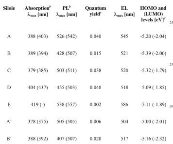
The UV-visible absorption, photoluminescence (PL) spectra have been measured both in solution and thin films. Electroluminescence (EL) spectra were obtained from single layer devices with a structure: ITO/PEDOT:PSS/ silole 50 nm/ Ca. The most relevant data obtained from these spectra are
190
collected in Table 2. Figures 3 and 4 are representative of the two behaviours that are encountered in this series of molecules. As it is seen in figure 3, compound A, A’, C or E display a broad absorption band in the range of 368 nm and 389 nm which is characteristic of the π → π* transition in the
195
silole ring.33 However, as it is seen in Figure 4, in the
compounds B, B’ or D, this transition is overlapped by the well recognizable pattern of phenylanthracenes. The comparison of Figures 3 and 4 reveals that the siloles without anthracene side groups behave differently than those bearing
200
ones. In the first family (siloles A, A’, C and E) all the emission spectra are nearly superimposable whatever the excitation mode or the physical state (solution vs thin film). The most important deviation is found with silole C in which a shift of ca. 9 nm is found between the PL and the EL spectra
205
(Table 2). In the second family (siloles B, B’ and D), the PL and EL spectra show differences both in the position of their emission maxima and in their shape, as exemplified in figure 4 with silole D. In solution, the anthracene moieties appear to Figure 1. DFT-optimized (B3LYP-6/31G) molecular structures of siloles A (top) and
B’ (bottom).
Figure 2. X-ray structure of silole 11. The CH2Cl2 crystallization molecule has been removed for sake of clarity.
Figure 4. Normalized UV-visible (), photoluminescence (in solution: } and thin
film: ) and electroluminescence (⎯) spectra of silole D.
Figure 3. Normalized UV-visible (), photoluminescence (in solution: } and thin
210
be mainly responsible of the emission, as attested by the vibronic coupling seen on the curves. Moreover, it is worthy to note that the Stocke’s shift that is observed with this second family (ca. 20-50 nm) is substantially smaller than with the first one (ca. 120-140 nm). As usually observed for the
215
2,3,4,5-tetraphenylsiloles, the quantum yields in solution are rather low (Table 2), the lowest value being found with E in which two silole rings are presents in the structure. This behaviour likely originates from resonant photon absorption phenomenon, since there is a substantial overlap between the
220
absorption and the emission spectra. Moreover this observation, which indicates that the two siloles rings behave independently, is in good agreement with their perpendicular arrangement in the molecular structure (see above). Interestingly, the presence of either 9-phenylanthracene or
225
9,10-diphenylanthracene highly fluorescent subunits (see below) in the molecular structures of siloles B, B’ and D has no positive effect on their quantum yields. Along with what is observed in the fluorescence spectra, this indicates that a large amount of energy is transferred from the anthracene
230
chromophores to the silole and then released via non-radiative processes. Finally, semi-quantitative measurements of the fluorescence quantum yields on thin films have been also performed. The following sequence have been found: B ≈ B’ > D > A > A’> C > DPA > Perylene ≈ E where DPA
(9,10-235
diphenylanthacene, φem (solution) = 1.00) and P Perylene (φem
(solution) = 0.94)45 are given for comparison. On account to
the AIE phenomenon,20, 21 the siloles display a very strong
fluorescence in the solid state that exceeds both DPA and Perylene which possess nearly quantitative quantum yields in
240
solution.
To better understand the optical data, we now turn to a description of the main characteristics of the HOMO and LUMO levels as calculated at the DFT level. The analysis of
the HOMO and LUMO wave functions shown for siloles A
245
and B in Figure 5 show the typical pattern of tetraphenylsiloles.46, 47 The HOMO wavefunctions show a
very similar spatial distribution with an antibonding character between the silole ring and the phenyl rings located at the 2,5-positions. The same similarity is found with the LUMO
250
wavefunctions in which bonding character is observed between the silole ring and the adjacent phenyl rings. The energies of the HOMO and LUMO orbitals (Table 2), which do not vary on a large extend upon modification of the substituents, are in the range of what is usually reported for
255
tetraarylsiloles. The examination of the wavefunctions calculated for siloles A’ and B’ (Figure 6 for B’) show a nearly identical orbital distribution on the tetraphenylsilole core. However, in contrast to their parents A and B, very few electron probability density is found on either the
260
dipyridylamino or the phenylanthracene moieties. This illustrates the expected disruption of the conjugation brought about by the diphenylether bridges, and the reason why the emission maximum of these two molecules is blue-shifted of 20 nm when compared with their parents A and B.
265
(iv) Electroluminescence properties and balance of charge carriers
In order to study the EL properties, single layer devices have been investigated, with the following structure: ITO/PEDOT:PSS/ silole 50 nm/ Ca. The electroluminescent
270
spectra are shown in Figure 7. As observed during the photoluminescence studies, only the silole ring contributes to the emission and device based on molecule A is 20 nm Table 2. Main values of the optical properties (UV-Visible and
fluorescence spectra) in solution and in thin films.a
Silole Absorptionb λmax [nm] PLb λmax [nm] Quantum yieldc EL λmax [nm] HOMO and (LUMO) levels [eV]d A 388 (403) 526 (542) 0.040 545 -5.20 (-2.04) B 389 (394) 428 (507) 0.015 521 -5.39 (-2.00) C 379 (385) 503 (511) 0.038 520 -5.32 (-1.79) D 404 (437) 455 (503) 0.040 518 -5.09 (-1.85) E 419 (-) 538 (557) 0.002 586 -5.11 (-1.89) A’ 378 (375) 505 (505) 0.006 504 -5.00 (-2.01) B’ 388 (392) 407 (507) 0.020 517 -5.16 (-2.32)
a The values recorded with thin solid films are between parentheses. b
Measured in CH2Cl2. c Measured in solution, quantum yield relative to
perylene (φem = 0.94). d From B3LYP-6/31G* DFT calculations.
Figure 5. B3LYP/6-31G*-calculated highest occupied (HOMO) and lowest
unoccupied (LUMO) molecular orbitals for siloles A and B.
Figure 6. B3LYP/6-31G*-calculated HOMO and LUMO molecular orbitals for silole B’.
redshift compared to the others. All the emissions correspond to the yellow-green domain on the chromatic diagram of the
275
Commission Internationale de l’Eclairage. Their
corresponding current density–voltage and luminance–voltage are presented in figure 3 (a) and figure 3 (b) respectively. When compared with the calculated HOMO and LUMO energy levels of the siloles (see Table 2), the high work
280
function of the anode ITO/PEDOT:PSS (-5.2 eV) and the low one of the calcium cathode (-2.9 eV) are suitable to favour the injection of both charge-carriers in the active layer. As a consequence, threshold voltage values generally below 4V are necessary to start of detection of luminance of the device
285
(Table 3). Moreover, with the exception of siloles C and E, all the molecules presented here display quite good luminous efficiencies (Le) for single-layer devices. In terms of
performances, D exhibits the best values with a threshold voltage below 3 V and a luminous efficiency Le of 0.75 cd/A
290
at 7 V. At the opposite, C and E are weakly electroluminescent. Indeed, these molecules need high applied voltages to reach the same order of current density than with A, B or D.
To better understand the origin of these different
295
behaviours and to try to outline the relationships that may exist between the molecular structure and the balance of charge-carriers in this series of molecules, one has to consider the factors that determine the efficiency of an OLED. Actually, this may approximately be calculated by the
300
following equation:48, 49
η
external= γ.η
recomb.η
ST.η
optical.Φ
PL(1)
where ηexternal is the total power efficiency of the device, γ305
is the balance of charge-carrier, ηrecomb represents the
recombination probability of injected holes and electrons, ηST
is the ratio of singlet and triplet excitons contributing to the
radiative recombination, ηoptical is the efficiency of the optical
outcoupling from the device, and ΦPL is the quantum yield of
310
fluorescence of the emissive material. By spin statistics, ηST,
which is the ratio of singlet to triplet excitons, should be ηST =
0.25, since parallel spin pairs will recombine to triplet excitons while antiparallel spin pairs will recombine to singlet and triplet excitons. Thus, for fluorescent emitters, we find
315
ηST = 0.25, which is a severe limitation of quantum efficiency
of an OLED. Concerning the optical outcoupling efficiency, a simple estimation regarding the OLED as classical optics device shows that a flat device with typical refractive index of the organics layers of 1.7, deposited on ITO/glass, achieves
320
approximately 20% outcoupling. Therefore, the first factor that defines the efficiency of an OLED on which we can play
from a molecular engineering point of view is the balance of charge-carrier (γ).
To analyze the result of molecular engineering on the
325
silole core in terms of balance of charge carriers, one has still to take into account both the charge transport processes and the quantum yield of fluorescence in the solid state of each molecule. Concerning the first issue, at least two parameters have to be taken into consideration: the orbital energy levels
330
and the organization of the molecules in the thin film.27, 41, 50, 51 In previous works we have studied the transport properties
of siloles A and B.41
Actually, they have a very close behaviour on account to their similarities both in terms of molecular organization (they form amorphous films) and in
335
terms of energy levels and orbital distribution (see above).27, 41, 50 Therefore, it seems reasonable to set the factor η
recomb in
Eq. 1 to a same arbitrary value for all the series of molecules studied here. In this way, the comparison of the luminous efficiencies corrected by the relative solid-stateΦ PL value
340
should allow to estimate the effect of molecular engineering on the balance of charge carriers.
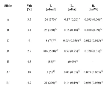
Table 3. The luminance (L), luminous efficiency (Le) and energetic efficiency (Re)
of siloles operating in ITO/PEDOT:PSS/Silole/Ca OLEDs.a
Silole Vth [V] L [cd/m²] Le [cd/A] Re [lm/W] A 3.5 26 (370)b 0.17 (0.20) b 0.095 (0.06)[b] B 3.1 25 (350)[b] 0.16 (0.18)[b] 0.100 (0.09)[b] C 9 8 (74)[c] 0.05 (0.036)[c] 0.012 (0.015)[c] D 2.9 80 (1550)[c] 0.52 (0.75)[c] 0.320 (0.35)[c] E 4.5 - (86)[c] - (0.09)[c] - A’ 18 5 (5)[b] 0.03 (0.03)[b] 0.003 (0.003)[b] B’ 4.2 21 (290)[c] 0.14 (0;19)[c] 0.060 (0.060)[c]
a Values measured at a current density of 20 mA/cm². b Value between
parentheses measured at 100 mA/cm². c Value between parentheses
measured at 200 mA/cm². 0 0.2 0.4 0.6 0.8 1 1.2 400 450 500 550 600 650 700 750 800 A B C D E No rm al iz ed EL In te n s it y ( a rb . u n it s ) Wavelength (nm)
From semi-quantitative measurements we have found the following sequence for the solid- state photoluminescence quantum yield ΦPL : B ≈ B’ > D > A > A’> C > E. By using
345
the procedure of normalization described in the experimental part, we have found that the photoluminescence intensity of B is ca. 1.5 times higher than the one of D, ca. 2.3 times higher than the one of A, ca. 2.8 times higher than the one of A’ and more than 20 times higher than the one of C (the value for E
350
is not given since it is of the same order than the error on the measurement). Therefore, the ratio Le over ΦPL, should give a
good indication on the correlation between the balance of charge carriers in the device and the hole carrier moieties (h+:
dipryridylamino or anthracenyl side-groups) over the electron
355
carrier moieties (e-: silole ring) present in the molecular
structure (Table 4).
From the examination of Table
4, it appears that the
360
major trend is that the more the h+ /e- ratio is
high, the more the balance of charges appears to be
365
improved. This result is well in line with the fact that the silole ring possesses an exceptional electron
370
carrier ability 26-28
that widely exceeds the hole carrier ability of the organic groups grafted to it. As a
375
consequence a large number of hole-transporting groups are needed to correct the balance of charge. Therefore, the silole D in which the h+ /e
-ratio is equal to 4 displays the best luminous efficiency. In the case of the silole C, in spite of a similar ratio, the
380
performances are disappointing since luminance and efficiencies (see table 2) are one order of magnitude lower than A and B at 20 mA/cm2. Moreover the current density is
considerably lowered than the one observed with the other molecules at a considered applied voltage. This phenomenon
385
may be attributed to two main reasons: i) this silole posses a weak solid-state ΦPL when compared to D, and ii) the four
dypirydilamino groups generate a strong steric hindrance which disfavours the electron transfert between the silole rings in the device.
390
The comparison of siloles A and B allows in which the h+ /e- ratio is equal to 2 allows us to estimate the relative ability
of the side-group to transport holes. They are both equivalently efficient in OLEDs but A is characterized by a Le
395
/ΦPL ratio of 0.39 whereas the one of B that is 0.16. In other
words, the dipyridylamino groups appear to be more efficient than anthracenyl ones as hole carriers to correct the balance of charges in silole-based devices. This may originates from the fact that anthracene entities not only enhance the holes current
400
compared to the dipyridylamine ones, but also increase the electron current, leading to a smallest correction of the balance of charge carriers. The comparison of siloles A, A’, B and B’ allows us now to evaluate the importance of the conjugation between both the charge carriers since the
405
presence of the diphenyl bridge has been shown to isolate both the moieties from an electronic point of view (see above). The disruption of the conjugation in silole A’ is accompanied by a marked decrease of the efficiency when compared to A, while the solid-state ΦPL of both are close
410
enough. In contrast to that, the same modification only weakly affects the efficiency of the devices based on siloles B and B’.
Conclusions
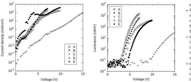
10-5 10-4 10-3 10-2 10-1 100 101 102 103 0 5 10 15 A B C D E C u rr e n t d e n s it y (m A /cm² ) Voltage (V) 10-2 10-1 100 101 102 103 104 0 5 10 15 A B C D E Lu m in a n c e ( c d/ m ²) Voltage (V)Figure 8. (a) Current-density-voltage characteristics for devices based on /PEDOT:PSS/Silole (50 nm)/Ca, and (b) Corresponding
luminance-voltage characteristics.
Table 4.. The luminous efficiency (Le), relative solid-state PL quantum
yield (ΦPL) and the hole carrier to the electron carrier formal ratio (h+/e-)
of siloles operating in ITO/PEDOT:PSS/Silole/Ca OLEDs. Silole Le a [cd/A] Relative solid-state ΦPL Le/ΦPL [cd/A] h+ /e-b A 0.17 0.44 0.39 2 B 0.16 1.00 0.16 2 C 0.05 <0.05 >1.00 4 D 0.52 0.67 0.78 4 E - - - 1 A’ 0.03 0.36 0.08 2 B’ 0.14 1.00 0.14 2
a Values measured at a current density of 20 mA/cm². b A silole ring
accounts for 1 e- whereas either an anthracenyl or a dipyridylamino
In this paper we showed that the balance of charge carriers can be improved by assembling different entities. The central silole ring
415
has been functionalized by hole transporting groups. Two solutions have been investigated. On the one hand, dipyridylamino have been compared to anthracene groups. Performances had not been improved due to enhancement of both charge carriers transport. On the other hand, two new molecules
420
have been synthesized containing four hole transporting groups for one silole ring. Finally, the energetic efficiencies have been enhanced by a factor six using the same device structure using suited hole transporting groups and appropriate grafted positions.
Experimental
425
General methods and device performance measurements Solvents were distilled prior to use. THF and ether were dried over sodium/benzophenone, and distilled under Argon. All the reactions were carried out under argon atmosphere. 1H, 13C and 29Si NMR spectra were recorded on a Bruker Advance
430
200 DPX spectrometer, the FT-IR spectra on a Thermo Nicolet Avatar 320 spectrometer, the UV-visible spectra on a Secomam Anthelie instrument and the MS spectra on a Jeol JMS-DX 300 spectrometer. I-V characteristics were recorded with a Keithley 2400 Sourcemeter, L-V with a photodiode
435
placed under the OLED and coupled to an HP multimeter. Electroluminescence spectra were measured using an Ocean Optics PC2000 CCD spectrometer. All electroluminescent devices were kept are characterized in a glove box under nitrogen. Fluorescence spectra in thin film were recorded with
440
a Edinburgh Instruments Ltd spectrofluorimeter. Absorption spectra in thin film were realized with an UV-visible SAFAS Monaco 190 DES spectrometer. Current-voltage (I-V) characteristics were recorded using a Keithley 4200 Semiconductor analyser and luminance-voltage (L-V) with a
445
photodiode calibrated with a Minolta CS-100 luminancemeter. Electroluminescence (EL) spectra were measured using an Ocean Optics HR2000 CCD spectrometer. All electroluminescent devices were fabricated and characterized in a glove box under nitrogen with [02] and [H2O] less than
450
0.1 ppm. The semi-quantitative solid state quantum yields have been measured on evaporated films of the same thickness and corrected by the corresponding absorption coefficient at the excitation wavelength (380 nm). In order to compare materials, cares have been taken for experimental
455
conditions. Spectrofluorimetre parameters were kept unchanged from a sample to another, thickness of the thin films were the same and the fluorescence spectrum of each molecule has been corrected by the corresponding absorption coefficient at the excitation wavelength. An excitation
460
wavelength at 380 nm has been selected, since all maxima absorption bands are localized in this domain.
X-ray diffraction
The diffraction intensities for silole 11 were collected at
465
the joint X-ray Scattering Service of the Institut Charles Gerhardt and the Institut Européen des Membranes of the University of Montpellier II, France, at 175 K using an Oxford Diffraction Xcalibur-I diffractometer. The structure
was solved by ab-initio (charge-flipping) methods using
470
SUPERFLIP52 and refined by least-squares methods on F
using CRYSTALS,53 against |F| on data having I>2σ(I);
R-factors are based on these data. Hydrogen atoms were located from difference Fourier synthesis. The CH2Cl2 crystallization
molecule was found to be heavily disordered. Two carbon
475
positions and seven chlorine position were found. The total site occupancy of the carbon positions were strongly restrained to 1 and that of the chlorine positions to 2. Restraints were also put on the Uiso parameters of carbon and
chlorine in order to have them approximately equal. No
480
attempts were made to place the proton sites for the two solvent carbon atoms. Basic structural data for silole 11 (C27H22BrSi,CH2Cl2; two solvent hydrogens not placed):
a=13.8694(8) Å, b=14.3213(8) Å, c=26.3741(14) Å, α=90°,
β=98.256(4)°, γ=90°, V=5184.4(5) Å3, space group C2 1/c,
485
50775 reflections measured, 3634 independent reflections with I>2σ(I) used for refinement with 307 parameters and two restraints. R=0.0391. wR= 0.0383. Full details can be found in the accompanying cif-file.
Device fabrication
490
Devices of ca. 10 mm2 were fabricated on ITO-coated
glass substrates (Merck, thickness ≈ 115 nm, sheet resistance ρ ≈ 17 Ω/□). After the cleaning process in trichloroethylene, ethanol and deionised water, an UV-ozone treatment was performed during 15 min. Then, a 50 nm-thick layer of
495
PEDOT-PSS was spun coated at 5000 rpm on top of ITO and baked at 80 °C for about 1 hour. PEDOT-PSS is a conducting polymer, acting as a buffer, in reducing short circuit problems induced by the ITO roughness. It weakly increases the work-function of the anode and acts as a barrier to oxygen and
500
indium diffusion from ITO.54 On the PEDOT-PSS layer, the
organic compounds as well as the cathodes were thermally evaporated under secondary vacuum (10-6 mbar). The
deposition rate of the silole layer was set at about 1 nm/s with a thickness of 50 nm measured in situ using a quartz balance
505
and ex situ using a Tencor AS-IQ profilometer. Finally, a 80 nm-thick calcium layer capped by 100 nm thick aluminium layer were evaporated through a shadow mask on top of the silole derivative. Each step of their preparation and characterization took place in glove box under inert
510
atmosphere.
Preparation of 9-[4-(4-Bromo-phenoxy)-phenyl]anthracene (4)
A solution of n-BuLi 2.5 M in hexane (7.7 mL, 19 mmol)
515
was added to an ethereal solution (70 mL) of 4,4’dibromodiphenylether (6.25 g, 19 mmol) cooled at –78 °C. The reaction mixture was left under stirring for 0.5 h at this temperature and anthrone was added by small portions (3 g, 15 mmol). This mixture was left under stirring for 3 h at
-520
78°C and the temperature is allowed to reach slowly the room temperature. An aqueous solution of HCl (0.5 M) was then added to the reaction mixture until a pH of 4-5 was reached and extracted with Et2O. After the usual processing, the
resulting residue was subjected to a silicagel column
525
white-yellow solid (yield : 50 %). Mp: 149 °C. 1H NMR (CDCl3, δ, ppm) : 8.54 (s, 1H), 8.09 (d, 3J(H,H) = 8, 2H), 7.75 (d, 3 J(H,H) = 8 Hz, 1H), 7.60-7.37 (m, 8H), 7.23 (d, 3J(H,H) = 9 Hz, 2H), 7.12 (d, 3J(H,H) = 9 Hz, 2H).13C NMR (CDCl 3, δ, 530 ppm) : 158.81, 156.71, 136.56, 134.35 133.27, 133.15, 131.79, 130.79, 128.83, 127.13, 127.07, 125.86, 125.55, 121.33, 119.01, 116.45. . HRMS (FAB+, m-nitrobenzyl alcohol matrix) m/z : calcd for [M+H]+ C
26H17BrO : 424.0463; found : 424.0456. 535 Preparation of [4-(4-bromo-phenoxy)-phenyl]di-pyridyn-2-yl-amine (6) A mixture of 4,4’-dibromodiphenylether (7.14 g, 21.7 mmol), di-2-pyridylamine (1.50 g, 8.70 mmol), K2CO3 (1.40
g, 10.4 mmol) and CuSO4.5H2O (0.217g, 0.87 mmol) in water
540
(20 mL) and CH2Cl2 (100 mL) was stirred well and
evaporated to dryness in vacuum. The mixture was ground in a mortar and 3-5 drops of CH2Cl2 were added to this mixture.
The mixture was heated in a schlenk tube at 210 °C for 6 h. After being cooled at room temperature, the mixture was
545
dissolved in CH2Cl2 (100 mL) and water (100 mL) and
extracted. After evaporation of the solvent, the residue was subjected to column chromatography CH2Cl2/THF (95/5) to
afford compound 6 as a white solid (yield: 80%).%). Mp: 102 °C. 1H NMR (CDCl 3, δ, ppm) : 8.33 (dd, 3J(H,H) = 6, 3J(H,H) 550 = 2 Hz, 2H), 7.62 (td, 3 J(H,H) = 7, 3J(H,H) = 2 Hz, 2H ), 7.47 (d, 3J(H,H) = 9 Hz, 2H), 7.21 (d, 3J(H,H) = 6 Hz, 2H), 7.00-6.81 (m, 8H).13C NMR (CDCl 3, δ, ppm) : 157.99, 156.17, 154.50, 148.50, 148.47, 140.33, 137.63, 128.92, 120.82, 119.84, 118.15, 116.71, 115.95. HRMS (FAB+, m-nitrobenzyl 555
alcohol matrix) m/z: calcd for [M+H]+ C22H16BrN3O :
418.0550; found: 418.0547.
Preparation of [4-(di-pyridin-2-yl-amino)-phenyl]-10-hydroxy-anthracen-9-one (8)
A solution of n-BuLi 2.5 M in hexane (10.5 mL, 26 mmol)
560
was added to a THF solution (100 mL) of 4-(2,2’-dipyridylamino)bromobenzene 725, 39 (7 g, 21 mmol) THF cooled at –78 °C. The reaction mixture was left under stirring for 1 h at this temperature. A THF solution (150 mL) of anthraquinone (8.73 g, 42 mmol) was then added to this
565
mixture and left under stirring for 8 h while allowing the temperature reach slowly the room temperature. An aqueous solution of HCl (1 M) was then added to the reaction mixture until a pH of 4-5 was reached and extracted with Et2O. After
the usual processing, the resulting residue was subjected to a
570
silicagel column chromatography (CH2Cl2/THF gradient: 97/3
to 90/10) to give 8 as a light yellow powder (yield: 43 %). Mp: 265-267 °C. 1H NMR (CDCl 3, δ, ppm) : 8.35-8.09 (m, 4H), 7.77 (dd, 3J(H,H) = 8, 3J(H,H) = 1 Hz, 2H), 7.62 (td, 3 J(H,H) = 7, 3J(H,H) = 2 Hz, 2H ), 7.58-7.48 (m, 4H), 7.37 (d, 575 3 J(H,H) = 9 Hz, 2H), 7.10 (d, 3J(H,H) = 9 Hz, 2H), 7.00-6.89 (m, 4H), 2.93 (s, 1H).13C NMR (CDCl 3, δ, ppm) : 182.32, 151.40, 148.71, 147.94, 138.45, 134.53, 130.75, 130.36, 128.71, 128.60, 127.37, 127.21, 126.65, 118.83, 117.04, 116.57, 73.5. HRMS (FAB+, m-nitrobenzyl alcohol matrix)
580
m/z: calcd for [M+H]+ C30H22N3O2 : 455.5227; found:
456.1704.
Preparation of (4-[10-(4-Bromo-phenyl)-anthracen-9-yl]-phenyl)di-pyridin-2-yl-amine (10)
A solution of n-BuLi 2.5 M in hexane (10 mL, 25 mmol)
585
was added to a THF solution (50 mL) of 1,4-dibromobenzene (5.92 g, 25 mmol) cooled at –78 °C. The reaction mixture was left under stirring for 1 h at this temperature and added via a cannula to a THF solution (100 mL) of 8 (3.26 g, 7.1 mmol) also cooled at –78 °C. This mixture was left under stirring for
590
8 h while allowing the temperature reach slowly the room temperature, then treated with aqueous HCl (1 M) to pH 4-5 and extracted with ether. The combined organic layers are dried over MgSO4 and evaporated under vacuum to afford
compound 9 as a viscous oil. The residue was then dissolved
595
in glacial acetic acid (60 mL), treated with NaH2PO4 (8.44 g,
95 mmol) and KI (4.22 g, 25 mmol), and heated to reflux for 20 min. After cooling, the reaction mixture was treated with cold water (300 mL) and extracted with CH2Cl2. After the
usual processing, the resulting residue was subjected to a
600
silicagel column chromatography (CH2Cl2/MeOH: 99/1) to
give 10 as a light yellow powder (yield: 20 %). Mp: 267 °C.
1H NMR (CDCl 3, δ, ppm) : 8.42 (dd, 3J(H,H) = 6, 3J(H,H) = 2 Hz, 2H), 7.93-7.62 (m, 8H), 7.53-7.39 (m, 10H), 7.21 (d, 3 J(H,H) = 7 Hz, 2H), 7.08 (td, 3J(H,H) = 7, 3J(H,H) = 2 Hz, 605 2H). 13C NMR (CDCl 3, δ, ppm) : 158.66, 148.85, 144.99, 138.46, 138.05, 136.04, 135.86, 133.49, 132.73, 132.06, 130.31, 130.16, 127.39, 127.07, 126.95, 125.73, 125.59, 122.05, 118.86, 117.81, 116.41. HRMS (FAB+, m-nitrobenzyl alcohol matrix) m/z: calcd for [M+H]+ C
36H24N3Br : 577.5097; 610 found: 578.1204. Preparation of 2-[4-(5-(4-bromo-phenyl)-1,1-dimethyl-3,4- diphenyl)silol-2-yl)phenyl)-5-(4-bromo-phenyl)-1,1-dimethyl-3,4-diphenyl-silole (11)
A mixture of lithium (0.055 g, 8 mmol) and naphthalene
615
(1.03 g, 8 mmol) in THF (15 mL) was stirred at room temperature under argon for 5 h to form a deep green solution of lithiumnaphthalenide. To the this mixture was added bis(phenylethynyl)dimethylsilane 1 (0.50 g, 2 mmol) in THF (10 mL). After stirring for 10 min, the reaction mixture was
620
cooled to 0 °C and [ZnCl2(tmen)] (tmen =
N,N,N',N'-tetramethylenediamine) (2.01 g, 8 mmol) was added, followed by an addition of THF (20 mL). After stirring for an hour at room temperature, a solution of 1,4-dibromobenzene (0.80 g, 34 mmol) in THF (20mL) and [PdCl2(PPh3)2] (0.10 g, 0.13
625
mmol) were successively added. The mixture was heated under reflux and stirred for 20 h. After hydrolysis by water, the mixture was extracted with Et2O. After evaporation of the
solvents, the resulting residue was subjected to a silicagel column chromatography (pentane/CH2Cl2 : 95/5) to yield 11
630
and the silole 12 as separate solids. The siloles were each recrystallized from a hexane/ CH2Cl2 mixture to give 11 as
dark yellow crystals (yield: 30 %) and 12 as light yellow crystals (yield: 20 %). Characterizations of silole 11: Mp: 310 °C. UV-Visible (λmax, nm, log ε): 255 (5.46), 399 (5.20). 1H
635 NMR (CDCl3, δ, ppm) : 7.15 (d, 3J(H,H) = 9 Hz, 4H), 6.96-6.86 (m, 12H), 6.74-6.64 (m, 12H ), 6.58 (s, 4H), 0.35 (s, 1H).13C NMR (CDCl 3, δ, ppm) : 155.14, 153.86, 142.14, 140.60, 139.26, 139.15, 138.84, 137.38, 131.46, 130.82, 130.32, 130.25, 128.93, 127.92, 127.82, 126.77, 126.63, 640
119.72, -3.31. 29Si NMR (CDCl
3, δ, ppm) : 8.09. HRMS
(FAB+, m-nitrobenzyl alcohol matrix) m/z: calcd for [M+H]+
C54H44Br2Si2 : 906.1348; found: 906.1330. Characterizations
of silole 11: the synthesis of this compound was previously described starting from 1-bromo, 4-iodobenzene.55 Mp: 224
645
°C. UV-Visible (λmax, nm, log ε): 250 (5.54), 361 (5.23). 1H
NMR (CDCl3, δ, ppm) : 7.28 (d, 3J(H,H) = 9 Hz, 4H),
7.10-7.02 (m, 6H), 6.81-6.75 (m, 8H ), 0.47 (s, 1H).13C NMR
(CDCl3, δ, ppm) : 154.90, 141.17, 139.04, 138.57, 131.56,
130.78, 130.24, 128.02, 126.94, 119.95, -3.52. 29Si NMR
650
(CDCl3, δ, ppm) : 8.23. HRMS (FAB+, m-nitrobenzyl alcohol
matrix) m/z: calcd for [M+H]+ C30H18Br2Si : 571.9996; found:
571.9985.
Preparation of 2,5-[Bis-(4-antrhracen-9-yl-phenyl)]-1,1-dimethyl-3,4-diphenyl-silole (B)
655
A mixture of lithium (0.055 g, 8 mmol) and naphthalene (1.03 g, 8 mmol) in THF (15 mL) was stirred at room temperature under argon for 5 h to form a deep green solution of lithiumnaphthalenide. To the this mixture was added bis(phenylethynyl)dimethylsilane 1 (0.50 g, 2 mmol) in THF
660
(10 mL). After stirring for 10 min, the reaction mixture was cooled to 0 °C and [ZnCl2(tmen)] (tmen =
N,N,N',N'-tetramethylenediamine) (2.01 g, 8 mmol) was added, followed by an addition of THF (20 mL). After stirring for an hour at room temperature, a solution of
9-(4-bromophenyl)-665
anthracene 334(1.59 g, 4.8 mmol) in THF (20mL) and
[PdCl2(PPh3)2] (0.10 g, 0.13 mmol) were successively added.
The mixture was heated under reflux and stirred for 20 h. After hydrolysis by water, the mixture was extracted with Et2O. After evaporation of the solvents, the resulting residue
670
was subjected to a silicagel column chromatography (pentane/CH2Cl2 : 85/15) and recrystallized from an hexane/
CH2Cl2 mixture to give B as a yellow crystalline powder
(yield: 35 %). Mp : 333 °C. UV-Visible (λmax, nm, log ε): 254 (6.37), 352 (5.22), 368 (5.43), 386 (5.50). 1H NMR 675 (CDCl3, δ, ppm): 8.51 (s, 2H), 8.07 (d, 3J(H,H) = 8 Hz, 4H), 7.72 (d, 3 J(H,H) = 8 Hz, 4H), 7.53-7.37 (m, 8H), 7.28-7.00 (m, 18H), 0.77 (s, 6H).13C NMR (CDCl 3, δ, ppm): 155.02, 146.18, 142.73, 139.58, 139.39, 137.53, 135.22, 133.80, 131.31, 130.62, 130.55, 129.18, 128.72, 127.90, 127.33, 680 126.81, 125.61, 125.47, -3.07. 29Si (CDCl 3, δ, ppm): 2.80. MS
(FAB+, m-nitrobenzyl alcohol matrix) m/z: 766 [M]+. Analysis calcd for C58H42Si : 90.82 %C, 5.52 %H ; found:
89.94 %C, 5.64 %H. Preparation of Silole A’
685
Same procedure as for silole B, using a solution of p-2,2’dipyridylaminophenyl-4-bromophenylether 650 (1.87 g,
4.4 mmol) in THF (20mL). After evaporation of the solvents, the resulting residue was firstly subjected to a silicagel column chromatography (MeOH/CH2Cl2 : 3/97) followed by
690
an alumina column (THF/CH2Cl2 : 5/95 to give A’ as a bright
yellow powder (yield: 42 %). Mp: 128 °C. UV-Visible (λmax, nm, log ε) : 277 (5.70), 377 (5.20). 1H NMR (CDCl 3, δ, ppm) : 8.35 (dd, 3 J(H,H) = 6, 3J(H,H) = 2 Hz, 4H), 7.58 (td, 3J(H,H) = 7, 3J(H,H) = 2 Hz, 4H), 7.16 (d, 3J(H,H) = 9 Hz, 4H), 7.14-695 6.86 (m, 30H), 0.52 (s, 6H).13C NMR (CDCl 3, δ, ppm) : 158.13, 155.05, 154.67, 153.77, 148.47, 140.48, 139.84, 138.88, 137.50, 135.11, 132.16, 132.06, 128.86, 127.53, 126.28, 119.69, 118.68, 117.98, 116.66, -3.60. 29Si NMR
(CDCl3, δ, ppm) : 7.87. MS (FAB+, m-nitrobenzyl alcohol
700
matrix) m/z: 937 [M+H]+. Analysis calcd for C
62H48N6O2Si: 79.46 %C, 5.16 %H, 8.97 %N ; found : 78.18 %C, 5,34 %H, 8.81 %N. Preparation of 2,5-Bis-[4-(4-anthracen-9-yl-phenoxy)-phenyl]1,1-dimethyl-3,4-diphenyl-silole (B’) 705
Same procedure as for silole B, using a solution of 4 (2.04g, 4.8 mmol) in THF (20mL). After evaporation of the solvents, the resulting residue was firstly subjected to a silicagel column chromatography (pentane/CH2Cl2 : 80/20)
and recrystallized from hexane/CH2Cl2 to give B’ as a yellow
710
powder (yield: 89 %). Mp: 264 °C. UV-Visible (λmax, nm, log ε) : 257 (6.47), 350 (4.95), 362 (5.13), 385 (5.10). 1H NMR (CDCl3, δ, ppm) : 8.54 (s, 2H), 8.09 (d, 3J(H,H) = 8 Hz, 4H), 7.76 (d, 3 J(H,H) = 8 Hz, 4H), 7.55-7.38 (m, 12H), 7.24 (d, 3J(H,H) = 8 Hz, 4H), 7.12-76.90 (m, 18H), 062 (s, 6H).13C 715 NMR (CDCl3, δ, ppm) : 157.18, 155.30, 154.27, 140.97, 139.39, 136.84, 135.57, 133.75, 132.95, 131.81, 130.83, 130.77, 130.44, 128.79, 128.00, 127.21, 127.01, 126.73, 125.79, 125.53, 119.21, 118.94, -3.10. 29Si NMR (CDCl 3, δ,
ppm) : 7.99. MS (FAB+, m-nitrobenzyl alcohol matrix) m/z:
720
951 [M+H]+. Analysis calcd for C
70H50O2Si: 88.39 %C, 5.30
%H; found : 86.69 %C, 5,48 %H.
Preparation of [5-(1,1-dimethyl-3,4-diphenyl-silol-2,5-yl)]bis(N,N,N’,N’-tetra-pyridin-2-yl-benzene-1,3-diamine) (C)
Same procedure as for silole B, using a solution of
3,5-725
bis(2,2’-dipyridylamino)bromobenzene36 5 (1.43 g, 4.4 mmol)
in THF (20mL). After evaporation of the solvents, the resulting residue was subjected to a silicagel column chromatography (MeOH/CH2Cl2 :10/90) and recrystallized
from an hexane/ CH2Cl2 mixture to give C as a bright yellow
730
powder (yield: 28 %). Mp: 135-137 °C. UV-Visible (λmax, nm, log ε) : 282 (5.80), 303 (5.79), 379 (5.10). 1H NMR (CDCl3, δ, ppm) : 8.31 (dd, 3J(H,H) = 6, 3J(H,H) = 2 Hz, 8H), 7.53 (td, 3 J(H,H) = 7, 3J(H,H) = 2 Hz, 8H), 6.92-6.82 (m, 22H), 6.72-6.66 (m, 6H), 6.51 (d, 3 J(H,H) = 2 Hz, 4H), 0.27 735 (s, 6H).13C NMR (CDCl 3, δ, ppm) : 157.56, 154.46, 148.20, 145.25, 142.38, 141.19, 138.25, 137.76, 120.51, 127.41, 126.16, 123.49, 121.87, 118.33, 117.24, -4.11. 29Si NMR
(CDCl3, δ, ppm) : 8.67. MS (FAB+, m-nitrobenzyl alcohol
matrix) m/z: 1091 [M+H]+. Analysis calcd for C
70H54N12Si: 740 77.03 %C, 5.16 %H, 15.40 %N ; found : 76.56 %C, 5.37 %H, 15.99 %N. Preparation of (10-[4-(1,1-Dimethyl-3,4-diphenyl-silol-2,5-yl)phenyl]-anthracen-9-yl)-bis-(dipyridin-2-yl-amine) (D) :
Same procedure as for silole B, using a solution of 10
745
(2.76 g, 4.8 mmol) in THF (20 mL). The residue was purified by silicagel column chromatography (CH2Cl2/THF gradient :
80/20 to 70/30) and crystallized from an hexane/CH2Cl2
mixture to afford D as a yellow solid (yield: 15 %). Mp: 376 °C. UV-Visible (λmax, nm, log ε) : 268 (6.30), 389 (5.57),
750
407 (5.63). 1H NMR (CDCl3, δ, ppm) : 8.45 (dd, 3J(H,H) = 6, 3
J(H,H) = 2 Hz, 4H), 7.91-7.86 (m, 4H), 7.77-7.86 (m, 8H),
7.05-7.02 (m, 8H), 0.88 (s, 6H). 13C NMR (CDCl 3, δ, ppm) : 159.81, 159.33, 155.16, 148.90, 144.84, 141.53, 139.74, 755 139.29, 138.57, 137.56, 136.75, 136.29, 135.81, 133.48, 130.80, 130.42, 130.33, 129.50, 128.82, 127.85, 127.23, 127.03, 125.26, 125.14, 119.73, 118.37, 117.15, -4.54. 29Si NMR (CDCl3, δ, ppm) : 8.27. MS (FAB+, m-nitrobenzyl
alcohol matrix) m/z: 1257 [M+H]+. Analysis calcd for
760 C90H64N6Si : 85.95 %C, 5.09 %H, 6.68 %N; found : 85.12 %C, 5.27 %H, 6.56 %N. Preparation of (4-[5-((1,1-Dimethyl-3,4-diphenyl)silol-2,5- yl)phenyl)-1,1-dimethyl-3,4-diphenyl-silol-2-yl)]-biphenyl-4-yl)-bis-(di-pyridin-2-yl-amine) (E) 765
A mixture of bisilole 11 (0.40 g, 0.44 mmol), Pd(PPh3)4
(0.05 g, 0.044 mmol), and toluene (50 mL) was stirred for 10 min. The boronic acid 1339 (0.76 g, 26 mmol) in 20 mL of EtOH and NaOH (0.18 g) in 20 mL of H2O were subsequently
added. The mixture was stirred and refluxed for 72 h and
770
allowed to cool to room temperature. The water layer was separated and extracted with CH2Cl2. The combined organic
layers were dried over MgSO4, and the solvents were
evaporated under reduced pressure. Purification of the crude product was carried out by silicagel column chromatography
775
(CH2Cl2/THF : 85/15) followed by the recrystallization of the
solid from a CH2Cl2/pentane mixture to afford E as a dark
yellowsolid in 86% yield. %). Mp: 334 °C. UV-Visible (λmax, nm, log ε ) : 284 (5.77), 311 (5.79), 419 (5.65). 1H NMR (CDCl3, δ, ppm) : 8.41 (dd, 3J(H,H) = 6, 3J(H,H) = 2 Hz, 4H), 780 7.66-7.57 (m, 8H), 7.39 (d, 3 J(H,H) = 8.5 Hz, 4H), 7.24 (d, 3 J(H,H) = 8.5 Hz, 4H), 7.07-6.96 (m, 24H), 6.88-6.83 (m, 4H), 6.72 (s, 4H), 0.53 (s, 12H). 13C NMR (CDCl 3,δ, ppm) : 157.62, 154.31, 153.68, 148.18, 141.58, 140.80, 139.04, 139.01, 138.96, 138.01, 137.14, 137.05, 129.98, 129.96, 785 129.37, 128.56, 128.13, 127.51, 127.41, 127.36, 126.36, 126.23, 126.15, 118.30, 116.95, -3.45. 29Si NMR (CDCl 3, δ,
ppm) : 7.95. MS (FAB+, m-nitrobenzyl alcohol matrix) m/z: 1241 [M+H]+. Analysis calcd for C
86H68N6Si2 : 83.18 %C,
5.51 %H, 6.78 %N; found : 82.43 %C, 5.66 %H, 6.78 %N.
790
Aknowledgements
We would thanks the French ANR (PSICO project # ANR-07-BLAN-0281-01) and the Région Languedoc-Roussillon for their financial support and for the award of a BDI thesis.
References
795
1. C. W. Tang and S. A. VanSlyke, Appl. Phys. Lett., 1987, 51, 913. 2. J. H. Burroughes, D. D. C. Bradley, A. R. Brown, R. N. Marks, K.
Mackay, R. H. Friend, P. L. Burns and A. B. Holmes, Nature, 1990, 347, 539.
3. D. F. O'Brien, M. A. Baldo, M. E. Thompson and S. R. Forrest, Appl.
800
Phys. Lett., 1999, 74, 442.
4. M. A. Baldo, S. Lamansky, P. E. Burrows, M. E. Thompson and S. R. Forrest, Appl. Phys. Lett., 1999, 75, 4.
5. S. Lamansky, P. Djurovich, D. Murphy, F. Abdel-Razzaq, H. E. Lee, C. Adachi, P. E. Burrows, S. R. Forrest and M. E. Thompson, J. Am.
805
Chem. Soc., 2001, 123, 4304.
6. S. Welter, K. Brunner, J. W. Hofstraat and L. De Cola, Nature, 2003, 421, 54.
7. C. Borek, K. Hanson, P. I. Djurovich, M. E. Thompson, K. Aznavour, R. Bau, Y. Sun, S. R. Forrest, J. Brooks, L. Michalski and
810
J. Brown, Angew. Chem. Int. Ed., 2007, 46, 1109.
8. M. Cocchi, J. Kalinowski, D. Virgili, V. Fattori, S. Develay and J. A. Williams, J. Appl. Phys., 2007, 90, 163508.
9. A. Fischer, S. Chénais, S. Forget, M.-C. Castex, D. Adès, A. Siove, C. Denis, P. Maisse and B. Geffroy, J. Phys. D : Appl. Phys., 2006,
815
39, 917.
10. G. Gu, G. Parthasarathy and S. R. Forrest, Appl. Phys. Lett., 1999, 74, 305.
11. J. Birnstock, J. Blochwitz-Nimoth, M. Hofmann, M. Vehse, G. He, P. Wellmann, M. Pfeiffer and K. Leo, IDW Proceedings, 2004, 1265.
820
12. J. Dubac, C. Guerin and P. Meunier, in The Chemistry of Organic
Silicon Compounds, eds. Z. Rappoport and Y. Apeloig, Wiley,
Chichester, 1998, vol. 2, pp. 1961-2036.
13. J. Dubac, A. Laporterie and G. Manuel, Chem. Rev. , 1990, 90, 215. 14. S. Yamaguchi and K. Tamao, J. Chem. Soc., Dalton Trans., 1998, 22,
825
3693-3702.
15. J. Chen and Y. Cao, Macromol. Rapid Commun., 2007, 28, 1714. 16. S. Yamaguchi and K. Tamao, Bull. Chem. Soc. Jpn, 1996, 69, 2327. 17. N. Roques, P. Gerbier, U. Schatzschneider, J.-P. Sutter, P.
Guionneau, J. Vidal-Gancedo, J. Veciana, E. Rentschler and C.
830
Guérin, Chem. Eur. J., 2006.
18. N. Roques, P. Gerbier, J.-P. Sutter, P. Guionneau, D. Luneau and C. Guérin, Organometallics, 2003, 22, 4833.
19. CSD, Cambridge Structural Database (CSD), (2003).
20. J. Chen, C. C. W. Law, J. W. Y. Lam, Y. Dong, S. M. F. Lo, I. D.
835
Williams, D. Zhu and B. Z. Tang, Chem. Mater., 2003, 15, 1535-1546.
21. Y. Ren, Y. Dong, J. W. Y. Lam, B. Z. Tang and K. S. Wong, Chem.
Phys. Lett., 2005, 402, 468.
22. H. Murata, Z. H. Kafafi and M. Uchida, Appl. Phys. Lett., 2002, 80,
840
189.
23. J. Chen, B. Xu, K. Yang, Y. Cao, H. H. Y. Sung, I. D. Williams and B. Z. Tang, J. Phys. Chem. B., 2005, 109, 17086.
24. H. Y. Chen, W. Y. Lam, J. D. Luo, Y. L. Ho, B. Z. Tang, D. B. Zhu, M. Wong and H. S. Kwok, Appl. Phys. Lett., 2002, 81, 574.
845
25. L. Aubouy, P. Gerbier, N. Huby, G. Wantz, L. Vignau, L. Hirsch and J.-M. Janot, N. J. Chem., 2004, 28, 1086.
26. H. Murata, G. G. Malliaras, M. Uchida, Y. Shen and Z. H. Kafafi,
Chem. Phys. Lett., 2001, 339, 161-166.
27. N. Huby, G. Wantz, L. Hirsch, L. Vignau , A. S. Barrière, L. Aubouy
850
and P. Gerbier, J. Appl. Phys., 2006, 99, 084907.
28. G. Yu, S. Yin, Y. Liu, J. Chen, X. Xu, X. Sun, D. Ma, X. Zhan, Q. Peng, Z. Shuai, B. Tang, D. Zhu, W. Fang and Y. Luo, J. Am. Chem.
Soc., 2005, 127, 6335.
29. J. Pang, Y. Tao, S. Freiberg, X.-P. Yang, M. D'Iorio and S. Wang, J.
855
Mater. Chem., 2002, 12, 206.
30. J. Lee, Q.-D. Liu, D.-R. Bai, Y. Kang, Y. Tao and S. Wang,
Organometallics, 2004, 23, 6205.
31. K. Danel, T. H. Huang, J. T. Lin, Y. T. Tao and C. H. Chuen, Chem.
Mat., 2002, 14, 3860.
860
32. P. Raghunath, M. A. Reddy, C. Gouri, K. Bhanuprakash and V. J. Rao, J. Phys. Chem. A, 2006, 110, 1152-1162.
33. S. Yamaguchi, T. Endo, M. Uchida, T. Izumizawa, K. Furukawa and K. Tamao, Chem. Eur. J., 2000, 6, 1683-1692.
34. S. Murphy, X. Yang and G. B. Schuster, J. Org. Chem., 1995, 60,
865
2411.
35. F. Kong, X. L. Wu, G. S. Huang, R. K. Yuan, C. Z. Yang, P. K. Chu and G. G. Siu, Appl. Phys. A, 2006, 84, 203-206
36. W.-L. Jai, D.-R. Bai, T. McCormick, Q.-D. Liu, M. Motala, R.-Y. Wang, C. Seward, Y. Tao and S. Wang, Chem. Eur. J. , 2004, 10,
870
994.
37. M. Smet and W. Dehaen, Molecules, 2000, 5, 620.
38. M. Smet, J. Van Dijk and W. Dehaen, Tetrahedron, 1999, 55, 7859. 39. W.-L. Jia, D. Song and S. Wang, J. Org. Chem., 2003, 68, 701. 40. J. Lee, Q.-D. Liu, M. Motala, J. Dane, J. Gao, Y. Kang and S. Wang,
875
Chem. Mat., 2004, 116, 1869-1877.
41. N. Huby, L. Hirsch, L. Aubouy, P. Gerbier, A. van der Lee, F. Amy and A. Kahn, Phys. Rev. B, 2007, 75, 115416.
42. C. Lee, W. Yang and R. G. Parr, Phys. Rev. B, 1988, 37, 785. 43. R. A. Gaussian 98, M. J. Frisch, G. W. Trucks, H. B. Schlegel, G. E.
880
Scuseria, M. A. Robb, J. R. Cheeseman, V. G. Zakrzewski, J. A. Montgomery, Jr., R. E. Stratmann, J. C. Burant, S. Dapprich, J. M.
Millam, A. D. Daniels, K. N. Kudin, M. C. Strain, O. Farkas, J. Tomasi, V. Barone, M. Cossi, R. Cammi, B. Mennucci, C. Pomelli, C. Adamo, S. Clifford, J. Ochterski, G. A. Petersson, P. Y. Ayala, Q.
885
Cui, K. Morokuma, D. K. Malick, A. D. Rabuck, K. Ragha-vachari, J. B. Foresman, J. Cioslowski, J. V. Ortiz, A. G. Baboul, B. B. Ste-fanov, G. Liu, A. Liashenko, P. Piskorz, I. Komaromi, R. Gomperts, R. L. Mar-tin, D. J. Fox, T. Keith, M. A. Al-Laham, C. Y. Peng, A. Nanayakkara, M. Challacombe, P. M. W. Gill, B. Johnson, W. Chen,
890
M. W. Wong, J. L. Andres, C. Gonzalez, M. Head-Gordon, E. S. Replogle, and J. A. Pople, Gaussian, Inc., Pittsburgh PA, 1998., (1998).
44. L. Aubouy, N. Huby, L. Hirsch, A. Van der Lee and P. Gerbier, To
be published., 2008.
895
45. H. Du, R. A. Fuh, J. Li, A. Corkan and J. S. Lindsey, Photochem.
Photobiol., 1998, 68, 141.
46. S. Yamaguchi and K. Tamao, Bull. Chem. Soc.Jpn., 1996, 69, 2327. 47. C. Risko, G. P. Kushto, Z. H. Kafafi and J. L. Brédas, J. Chem.
Phys., 2004, 121, 9031.
900
48. Y. Shirota and H. Kageyama, Chem. Rev., 2007, 107, 953.
49. K. Walzer, B. Maennig, M. Pefeiffer and K. Leo, Chem. Rev., 2007, 107, 1233.
50. L. Aubouy, P. Gerbier, C. Guérin, N. Huby, L. Hirsch and L. Vignau,
Synth. Met., 2007, 157, 91.
905
51. V. Coropceanu, J. Cornil, D. A. da Silva Filho, Y. Olivier, R. Silbey and L.-L. Bredas, Chem. Rev., 2007, 107, 926.
52. L. Palatinus and G. Chapuis, J. Appl. Cryst., 2007, 40.
53. P. W. Betteridge, J. R. Carruthers, R. I. Cooper, K. Prout and D. J. Watkin, J. Appl. Cryst., 2003, 36, 1487.
910
54. A. V. Dijken, A. Perro, E. A. Meulenkamp and K. Brunner, Organic
Electronics, 2003, 4, 131-141.
55. F. Wang, J. Luo, J. Chen, F. Huang and Y. Cao, Polymer, 2005, 46, 8422.
![Table 1. Torsion angles [°] in siloles a](https://thumb-eu.123doks.com/thumbv2/123doknet/14295889.493287/4.892.74.395.101.488/table-torsion-angles-in-siloles-a.webp)