HAL Id: hal-02440149
https://hal-enac.archives-ouvertes.fr/hal-02440149
Submitted on 15 Jan 2020
HAL is a multi-disciplinary open access
archive for the deposit and dissemination of
sci-entific research documents, whether they are
pub-lished or not. The documents may come from
teaching and research institutions in France or
abroad, or from public or private research centers.
L’archive ouverte pluridisciplinaire HAL, est
destinée au dépôt et à la diffusion de documents
scientifiques de niveau recherche, publiés ou non,
émanant des établissements d’enseignement et de
recherche français ou étrangers, des laboratoires
publics ou privés.
Modal Analysis of Cylindrical Waveguides with 2D
Metamaterial Wall
Lucille Kuhler, Gwenn Le Fur, Luc Duchesne, Nathalie Raveu
To cite this version:
Lucille Kuhler, Gwenn Le Fur, Luc Duchesne, Nathalie Raveu. Modal Analysis of Cylindrical
Waveg-uides with 2D Metamaterial Wall. META 2018 9th International Conference on Metamaterials,
Pho-tonic Crystals and Plasmonics, Jun 2018, Marseille, France. �hal-02440149�
META 2018 CONFERENCE, ROUND-TRIP MARSEILLE CRUISE, JUNE 24 – JULY 1, 2018
Modal Analysis of Cylindrical Waveguides with 2D Metamaterial
Wall
Lucille Kuhler
1,2,3,*, Gwenn Le Fur
2, Luc Duchesne
3, Nathalie Raveu
11University of Toulouse, INPT, CNRS, Laplace, 2 rue Charles Camichel, Toulouse, France 2CNES, antennas department, 18 avenue Edouard Belin, Toulouse, France
3MVG Industries, 17 avenue de Norvege, Villebon Sur Yvette, France *corresponding author, E-mail: [email protected]
Abstract
In this article the Modal Expansion Theory (MET) is developed for 2D metamaterial cylindrical waveguides. A new code based on 2D Finite Element Method (FEM) is implemented to compute conformal surface impedances. The MET using this FEM code is successfully applied to waveguides with different 𝜃 -invariant metamaterials. For such cases, computation time is at least 30 times faster than the commercial software HFSS.
1. Introduction
In the space industry, the launch cost of spacecraft is a constraint. In order to lower it, the size and the weight of the used devices are reduced. Metamaterials in waveguides or horn antennas could be used in this purpose [1] - [4]. Thanks to their structuration electromagnetic properties which are not available in natural materials, can be created [5]. With metamaterials, it is possible to obtain a relative permittivity and/or permeability lower than one or less than zero [6] - [8]. In research, metamaterials are mostly defined by characterizing both permittivity and permeability. However another method consists in computing their surface impedances at any given volume height [9].
In [10], metamaterials are characterized with a new method called the Modal Expansion Theory. This method aims at studying waveguides [10] - [12]. With the MET, it is possible to characterize the dispersion properties of rectangular or cylindrical waveguides with constant anisotropic surface impedances. In [13], a 2D FEM code has been added to the MET and allows the characterization of dispersion properties of rectangular waveguides with metamaterial walls. Surface impedances are defined at any given volume height and vary with the frequency and incidence angle of the electromagnetic wave.
In this article, 2D metamaterial waveguides are characterized with the cylindrical MET. Thanks to the 𝜃- invariance of the structure, this new code is using a 2D FEM computation of the surface impedances deduced from the 3D FEM simplification. Conformal surface impedances are computed with this code. As in [13], the surface impedances are dependent on the frequency and incidence angle. The validation of the MET with this new 2D FEM code (for
conformal impedances) is presented. Hence the MET is applied on three different 2D metamaterial waveguides to obtain their dispersion diagrams. Results are compared to the dispersion diagrams obtained with HFSS. By using the MET, the computation time is drastically reduced to obtain equivalent results.
2. Characterization principles
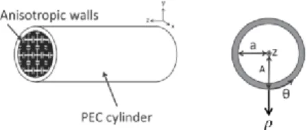
In this article, the MET [10] is proposed to characterize cylindrical waveguide with metamaterial walls. These waveguides are considered invariant along the 𝑧-axis, see Fig. 1. So electromagnetic fields have an 𝑒−𝛾𝑧 dependence,
with 𝛾 the propagation constant along the 𝑧 -axis. Furthermore the studied metamaterials are also invariant along the 𝜃-axis.
Figure 1: A cylindrical waveguide with anisotropic walls.
The metamaterial periodicity is supposed small compared to wavelength [6]. Therefore metamaterials are assumed to be equivalent to anisotropic surface impedances.
2.1. Modal Expansion Theory for cylindrical waveguides
In the cylindrical coordinate system, the surface impedance 𝑍𝑆′ is defined as follows:
𝐸𝑇
⃗⃗⃗⃗ = 𝑍𝑆′(𝐻⃗⃗⃗⃗⃗ × 𝑛⃗ )𝑇 (1)
where 𝐸⃗⃗⃗⃗ and 𝐻𝑇 ⃗⃗⃗⃗⃗ 𝑇 are the electric and magnetic fields
tangent to the cylinder surface, 𝑛⃗ the normal unit vector to the cylinder surface. It leads to two impedance definitions:
𝑍𝑇′ = − 𝐸𝜃 𝐻𝑍|𝜌=𝑎 , 𝑍𝑍′ = 𝐸𝑍 𝐻𝜃|𝜌=𝑎 (2)
2 The dispersion equation is determined in [11] from Helmholtz’s equation and the anisotropic boundary conditions. 𝑍𝑍′ 𝑍0(𝐽𝑚 ′ (𝑢 𝑎)) 2 −𝑍𝑇 ′ 𝑍0( 𝑘𝑐𝐽𝑚(𝑢𝑎) 𝑘0 ) 2 + (𝑍𝑍 ′𝑍 𝑇 ′ 𝑍02 + 1)𝑘𝑐𝐽𝑚(𝑢𝑎)𝐽𝑚 ′ (𝑢 𝑎) 𝑗𝑘0 +𝑍𝑍 ′ 𝑍0(( 𝑘𝑐 𝑘0) 2 − 1) (𝑚𝐽𝑚(𝑢𝑎) 𝑢𝑎 ) 2 = 0 (3)
where 𝑎 is the internal radius, 𝑢𝑎= 𝑘𝑐𝑎 , 𝑘𝑐 the cutoff
constant, 𝑘0 the free space wavenumber, 𝐽𝑚 the Bessel function of order 𝑚, 𝐽𝑚′ the derivative of the Bessel function
𝐽𝑚 and 𝑍0 the free space characteristic impedance .
In this article, cylindrical waveguides with 2D metamaterials due to an invariance along the 𝜃 -axis are of interest. Consequently only 0 order modes are studied. Metamaterials could be considered as anisotropic surface impedances but their shape should be undertaken. In [13] the MET with a 2D FEM code is successfully applied to rectangular waveguides with 2D metamaterials with invariance along the 𝑦 -axis. In this article, the FEM is developed to cylindrical waveguides with 2D metamaterials with invariance along the 𝜃-axis.
The equation (3) is simplified for 0 order modes [11] into:
[𝑗𝜔𝜇0𝐽0′(𝑢𝑎) + 𝑍𝑇′𝑘𝑐𝐽0(𝑢𝑎)]
× [𝑍𝑍′𝑗𝜔𝜖0𝐽0′(𝑢𝑎) + 𝑘𝑐𝐽0(𝑢𝑎)] = 0 (4)
where 𝜇0 is the free space permeability, 𝜖0 the free space
permittivity and 𝜔 angular frequency (by using the convention of electromagnetic fields dependent on 𝑒𝑗𝜔𝑡).
From (4) 𝑇𝐸0𝑛 and 𝑇𝑀0𝑛 modes could be characterized separately, whatever 𝑛 is. As a matter of fact in (4) either the first term is equal to zero or the second term. The first term with 𝑍𝑇′ will define 𝑇𝐸0𝑛 modes and the second term with
𝑍𝑍′ will define 𝑇𝑀0𝑛 modes.
2.2. Characterization of conformal metamaterials
As the waveguide is 𝜃 -invariant, the 3D FEM code is simplified into a 2D FEM code. In any 𝑃 plane of the cylindrical waveguide, a unit cell can be extracted, see Fig. 2.
Figure 2: A cylindrical waveguide with an example of 2D metamaterial unit cell.
Γ1 and Γ2 are periodic boundaries, Γ3 is the rotational axis
and ΓS is a boundary where the 𝑍𝑆 surface impedance (𝑍𝑇
and 𝑍𝑍) is defined. Ω′ is the plane where the 𝑍𝑆′ surface impedance (𝑍𝑇′ and 𝑍𝑍′) is computed. 𝐴 is the radius of the
waveguide, ℎ is the height of the metamaterial and 𝑝 the distance between Γ1 and Γ2.
The 𝑍𝑆′ conformal surface impedance (𝑍𝑇′ and 𝑍𝑍′ ) is
computed with the 2D FEM code in the Ω′ plane. 𝑍
𝑍′ defined
in (2) is generated by 𝐻𝜃, that is considered 𝜃 invariant; 𝑍𝑇′
defined in (2) is generated by 𝐸𝜃, and considered 𝜃 invariant. This code is inserted in the MET solution of (3).
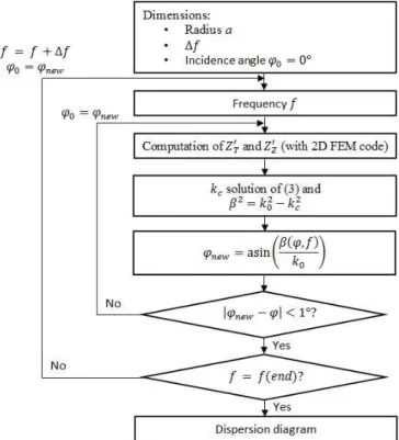
2.3. Recursive solution of dispersion equation
The 𝑍𝑆′ surface impedance (𝑍𝑇′ and 𝑍𝑍′) depends on the 𝜑
incidence angle [13] which is deduced from 𝛽, the phase constant along the 𝑧 -axis. The algorithm of Fig. 3 is implemented to compute the dispersion diagrams.
Figure 3: The MET algorithm to obtain 𝛽.
With this algorithm different 2D metamaterials (with a 𝜃 invariance) in cylindrical waveguides can be studied. A 3D FEM code is required to deal with 3D metamaterials or mode with angular dependency (𝑚 order different from 0).
3. Results
The method and the algorithm are validated in three different cases:
firstly in a corrugated waveguide,
subsequently the code is applied to a L-shape metamaterial,
In all these cases, results are compared to HFSS solutions. To study these waveguides with HFSS, the same method as [11] is used. Dispersion diagrams are obtained from the volume of the section represented in Fig. 5, 11 and 14 with dashed lines and using periodic boundary conditions, see Fig. 4. The propagation constant is computed thanks to the phase delay between two periodic boundary conditions and the distance between them. By using the eigenmode solver in HFSS, the frequency of each solution is given. The complete dispersion diagram is obtained by varying the phase delay between the two periodic boundary conditions from 0° to 180°.
Figure 4: A cylindrical representation of a waveguide with periodic boundary conditions and anisotropic surface simulated in HFSS.
3.1. Corrugated cylindrical waveguide
A corrugation invariant in 𝜃 direction is considered. The studied waveguide is represented Fig. 5.
Figure 5: A corrugated waveguide. The blue dashed section is the section used in HFSS and the red doted one is used in the MET.
For the MET, the unit cell is created with the open source software Gmsh [14] and represented in Fig. 6.a.
Figure 6: a) Unit cell mesh and dimensions:𝐴 = 39.3 𝑚𝑚 , 𝑎 = 23.58 𝑚𝑚 , 𝑑 = 14.3 𝑚𝑚 , ℎ = 15.72 𝑚𝑚 , 𝑝 = 10.3 𝑚𝑚 , and 𝑤 = 9.28 𝑚𝑚 . b) Dispersion diagrams of the corrugated cylindrical waveguide obtained with MET (dots) and HFSS (circles).
Both simulations are made with the same computer (Intel (R) Xeon (R), 1.8 𝐺𝐻𝑧 2 processors, 64 𝐺𝐵 of RAM). The dispersion diagrams are represented Fig. 6.b, they perfectly coincide for 0 order modes. The dispersion diagrams are obtained in 622 minutes with HFSS while it requires only 18 minutes with MET. Consequently the MET code is 34 times faster.
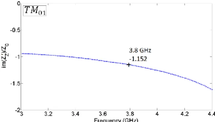
Since only 𝑇𝑀01 mode appears in this dispersion diagram,
only 𝑍𝑍′ is of interest. The figure 7 represents the 𝑍𝑍′ surface
impedance computed in the Ω′ plane.
Figure 7: The 𝑍𝑍′ surface impedance of the 𝑇𝑀01 mode of Fig. 6.b.
While the 𝑍𝑆 surface impedance (𝑍𝑇 and 𝑍𝑍) in Γ𝑆 is null,
𝑍𝑍′ in the Ω′ plane change with frequencies. This 𝑍𝑍′
impedance is computed with the algorithm of Fig. 3 which means that the 𝜑 incidence angle is different from one frequency to another.
In order to observe a 𝑇𝐸0𝑛 mode, the dispersion diagram of
Fig. 6.b is studied up to 7 𝐺𝐻𝑧 and represented in the Fig. 8.
Figure 8: Dispersion diagrams of the corrugated cylindrical waveguide obtained with MET (dots) and HFSS (circles).
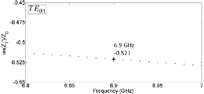
In this new dispersion diagram, two new 0 order modes are identified: the 𝑇𝑀02 and the 𝑇𝐸01 modes. Consequently 𝑍𝑍′
is of interest for the 𝑇𝑀02 mode and 𝑍𝑇′ is of interest for the
𝑇𝐸01 mode as explained in (4). Figure 9 represents the 𝑍𝑍′
surface impedance computed in the Ω′ plane for the 𝑇𝑀02 mode and figure 10 represents the 𝑍𝑇′ surface
4
Figure 9: The 𝑍𝑍′ surface impedance of the 𝑇𝑀02 mode of Fig. 8.
Figure 10: The 𝑍𝑇′ surface impedance of the 𝑇𝐸01 mode of Fig. 8.
Both figures lead to the same conclusion as Fig. 7: the 𝑍𝑆′
surface impedance (𝑍𝑇′ and 𝑍𝑍′) in the Ω′ plane changes with
frequencies, with the 𝜑 incidence angle and also are dependent on the mode.
3.2. Cylindrical waveguide with L-shape metamaterial
The studied waveguide is presented in Fig. 11. The L-shape metamaterial is also invariant along the 𝜃-axis.
Figure 11: A cylindrical waveguide with a L-shape metamaterial. The blue dashed section is the section used in HFSS and the red doted one is used in the MET.
As in the previous case, the unit cell is created with Gmsh from the red doted section of Fig. 11. Figures 12 represent the unit cell mesh used and the dispersion diagrams obtained with the MET (dots) and with HFSS (circles).
Figure 12: a) Unit cell mesh and dimensions: 𝐴 = 39.3 𝑚𝑚 , 𝑎 = 23.58 𝑚𝑚 , 𝑑1= 14.3 𝑚𝑚 , 𝑑2= 2.5 𝑚𝑚 , ℎ = 15.72 𝑚𝑚 ,
𝑝 = 10.3 𝑚𝑚 , 𝑝1= 2.5 𝑚𝑚, 𝑝2= 5.3 𝑚𝑚 , and 𝑤 = 5 𝑚𝑚 . b)
Dispersion diagrams of the corrugated cylindrical waveguide obtained with MET (dots) and HFSS (circles).
Both dispersion diagrams in Fig. 12.b perfectly coincide. Concerning the computation time with HFSS, the simulation lasts around 1032 minutes while this process takes only 20 minutes with the MET. Hence the time is divided by 51. The L-shape metamaterial changes the propagation properties of the waveguide (different modes and different orders). Indeed the cutoff frequency of the 𝑇𝑀01 mode is
now 3.11 𝐺𝐻𝑧 , while it was 3 𝐺𝐻𝑧 for the corrugated waveguide. Moreover the 𝑍𝑍′ surface impedance for the 𝑇𝑀01 mode is slightly different from the corrugation case
see Fig. 13.
Figure 13: The 𝑍𝑍′ surface impedance of the 𝑇𝑀01 mode of Fig.
12.b.
3.3. Cylindrical waveguide with stair-shape metamaterial
The last waveguide studied is a waveguide with a stair-shape metamaterial 𝜃-invariant, see Fig. 14.
Figure 14: A cylindrical waveguide with a stair-shape metamaterial. The blue dashed section is the section used in HFSS and the red doted one is used in the MET.
Figures 15 represent the unit cell and the dispersion diagrams.
Figure 15: a) Unit cell mesh and dimensions: 𝐴 = 39.3 𝑚𝑚 , 𝑎 = 23.58 𝑚𝑚 , 𝑑1= 14.3 𝑚𝑚 , 𝑑2= 7 𝑚𝑚 , ℎ = 15.72 𝑚𝑚 ,
𝑝 = 10.3 𝑚𝑚 , 𝑝1= 2.5 𝑚𝑚 , 𝑝2= 7.5 𝑚𝑚 , and 𝑤 = 5 𝑚𝑚 . b)
Dispersion diagrams of the corrugated cylindrical waveguide obtained with MET (dots) and HFSS (circles).
The dispersion diagrams are obtained with HFSS (circles in Fig. 15.b) in 1256 minutes and with the MET (dots in Fig. 15.b) it requires an eleven-minute computation times. The reduction time is around 114.
With this metamaterial the first mode is not the 𝑇𝑀01 but the
𝐸𝐻11 mode. Consequently the propagating modes and their
cutoff frequencies change again with the shape of the metamaterial. In this case, the 𝑇𝑀01 cutoff frequency is now
𝑓𝑐 = 3.49 𝐺𝐻𝑧 , while it was 3 𝐺𝐻𝑧 for the corrugated
waveguide. Moreover the 𝑍𝑍′ surface impedance of the 𝑇𝑀01 mode is divided by two at 3.8 𝐺𝐻𝑧 compared to the
previous cases, Fig. 16.
Figure 16: The 𝑍𝑍′ surface impedance of the 𝑇𝑀01 mode of Fig. 15.b.
4. Conclusion
The MET has been successfully applied to cylindrical waveguides with 2D metamaterial walls, for 0 order modes. The proposed method appears accurate and extremely faster than HFSS solution, at least 30 times faster. This method allows a comparison between the propagation characteristics of all kinds of 𝜃-invariant metamaterials. In this article three different waveguides have been studied. It has been proved that the shape of the metamaterial can modify the propagation properties in the waveguide. Furthermore all metamaterials can be defined by using their surface
impedance at any given volume height. In these three examples the surface impedances are computed at the same volume height ℎ and are different. They depend on the frequencies, on the 𝜑 incidence angle, on the propagating mode and on the metamaterial shape.
An extension of the method to 3D metamaterials is now under process. As metamaterials could be 𝜃-dependent, the 3D FEM code could no longer be reduced to a 2D FEM code. With this extension all kinds of metamaterial but also all the mode orders can be dealt with.
References
[1] J. G. Pollock and A. K. Iyer, "Below-Cutoff Propagation in Metamaterial-Lined Circular Waveguides," IEEE Transactions on Microwave Theory and Techniques, vol. 61, no. 9, pp. 3169-3178, September 2013.
[2] J. G. Pollock and A. K. Iyer, "Radiation Characteristics of Miniaturized Metamaterial-Lined Waveguide Probe Antennas," chez IEEE International Symposium on Antennas and Propagation USNC/URSI National Radio Science Meeting, Vancouver (Canada), July 2015. [3] J. G. Pollock and A. K. Iyer, "Miniaturized
Circular-Waveguide Probe Antennas using Metamaterial Liners," IEEE Transactions on Antennas Propagations, vol. 63, no. 1, pp. 428-433, January 2015.
[4] J. G. Pollock and A. K. Iyer, "Experimental Verification of Below-Cutoff Propagation in Miniaturized Circular Waveguides Using Anisotropic ENNZ Metamaterial Liners," IEEE Transactions on Microwave Theory and Techniques, vol. 64, no. 4, pp. 1297-1305, April 2016.
[5] R. A. Shelby, D. R. Smith and S. Schultz, "Experimental Verification of a Negative Index of Refraction," Science, vol. 292, pp. 77-79, april 2001. [6] D. R. Smith, W. J. Padilla, D. C. Vier, S. C.
Nemat-Nasser, and S. Schultz, "Composite Medium with Simultaneoustly Negative Permeability and Permittivity," Physical Review Letters, vol. 84, no. 18, pp. 4184-4187, May 2000.
[7] V. G. Veselago, "The Electrodynamics of Substances with Simultaneously Negative Values of ε and µ," Soviet Physics Upsekhi, vol. 10, no. 4, pp. 509-514, 1968.
[8] R. W. Ziolkowski and E. Heyman, "Wave Propagation in Media Having Negative Permittivity and Permeability," Physical Review E., vol. 64, n° 15, pp. 1-15, 2001.
[9] Q. Wu, M. D. Gregory, D. H. Werner, P. L. Werner and E. Lier, "Nature-Inspired Design of Soft, Hard and Hybrid Metasurfaces," chez 2010 IEEE Antennas and Propagation Society International Symposium (APSURSI), Toronto, Canada, July 2010.
6 [10] B. Byrne, Etude et Conception de Guides d'Onde et
d'Antennes Cornets à Métamatériaux, Toulouse: Thèse en vue de l'obtention du Doctorat de l'université de Toulouse, 2016.
[11] N. Raveu, B. Byrne, L. Claudepierre and N. Capet, "Modal Theory for Waveguides with Anisotropic Surface Impedance Boundaries," IEEE Transactions On Microwave Theory And Techniques, vol. 64, no. 64 pp. 1153-1162, 2016.
[12] B. Byrne, N. Capet and N. Raveu, "Dispertion Properties of Corrugated Waveguides Based on the Modal Theory," EUCAP 2014: 8th EUropean Conference on Antennas and Propagation, The Hague, Netherland, 6-11 April 2014.
[13] B. Byrne, N. Raveu, N. Capet, G. Le Fur and L. Duchesne, "Modal analysis of Rectangular Waveguides with 2D Metamaterials," Progress In Electromagnetics Research C, vol. 70, pp. 165-173, 2016.
[14] C. Geuzaine, and J.-F. Remacle "Gmsh: A three-dimensional finite element mesh generator with built-in pre- and post-processing facilities," International Journal for Numerical Methods in Engineering, vol. 79, n° 111, pp. 1309-1331, 2009.