Publisher’s version / Version de l'éditeur:
Vous avez des questions? Nous pouvons vous aider. Pour communiquer directement avec un auteur, consultez la première page de la revue dans laquelle son article a été publié afin de trouver ses coordonnées. Si vous n’arrivez pas à les repérer, communiquez avec nous à PublicationsArchive-ArchivesPublications@nrc-cnrc.gc.ca.
Questions? Contact the NRC Publications Archive team at
PublicationsArchive-ArchivesPublications@nrc-cnrc.gc.ca. If you wish to email the authors directly, please see the first page of the publication for their contact information.
https://publications-cnrc.canada.ca/fra/droits
L’accès à ce site Web et l’utilisation de son contenu sont assujettis aux conditions présentées dans le site
LISEZ CES CONDITIONS ATTENTIVEMENT AVANT D’UTILISER CE SITE WEB.
Canadian Building Digest, 1979-01-01
READ THESE TERMS AND CONDITIONS CAREFULLY BEFORE USING THIS WEBSITE.
https://nrc-publications.canada.ca/eng/copyright
NRC Publications Archive Record / Notice des Archives des publications du CNRC :
https://nrc-publications.canada.ca/eng/view/object/?id=ccde0331-086c-41a9-8fff-7b82e29f8144
https://publications-cnrc.canada.ca/fra/voir/objet/?id=ccde0331-086c-41a9-8fff-7b82e29f8144
NRC Publications Archive
Archives des publications du CNRC
For the publisher’s version, please access the DOI link below./ Pour consulter la version de l’éditeur, utilisez le lien DOI ci-dessous.
https://doi.org/10.4224/40000675
Access and use of this website and the material on it are subject to the Terms and Conditions set forth at
Joints in conventional bituminous roofing systems
Canadian Building Digest
Division of Building Research, National Research Council Canada
CBD-202
Joints in Conventional Bituminous Roofing Systems
Please note
This publication is a part of a discontinued series and is archived here as an historical reference. Readers should consult design and regulatory experts for guidance on the applicability of the information to current construction practice.
Originally published January 1979. R.G. Turenne
As construction materials expand and contract when exposed to changes in temperature, it is common practice not to attempt to restrain them. Instead they are incorporated in a structure in a manner that will accommodate their movement.
Although this technique is quite acceptable for materials that behave elastically, a bituminous built-up roofing membrane has viscoelastic properties and thermally induced movements are not necessarily reversible (CBD 181). They cannot be controlled in the same way as those in masonry walls or concrete slabs on grade. Various types of membrane control joint are used to provide for expansion and contraction and to prevent splitting or excessive shrinkage at roof edges. They do not, however, always perform as intended.
This Digest will attempt to provide guidelines for the improved design and positioning of joints in a conventional roofing system.
Types of Roofing Joint
Three types of joint have been used in conjunction with built-up roofs:
The first involves the membrane only and is usually referred to as a membrane control joint. It is intended to relieve membrane stresses by allowing the membrane to move.
The second type is installed to coincide with a movement joint in the structure and is called a roof expansion joint. Its role is to prevent movements of expansion and contraction in the structure from being transmitted to the membrane.
A third type of joint is used to divide irregular-shaped roofs into square or rectangular areas and is known as the roof area divider.
Membrane Control Joints
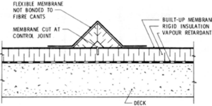
Membrane control joints (Figure 1) are often installed after the roofing membrane has been placed. Allowance for movement is made by cutting the membrane and insulation along a predetermined line. Back-to-back cant strips are then adhered to the membrane over the cut and are, in turn, covered with an elastic sheet material that is bonded to the membrane on either side of the cant strips.
Figure 1. Membrane control joint.
Unfortunately, the use of membrane control joints is based on a number of invalid
assumptions, one being that bituminous materials behave elastically and that all thermally induced movements are completely reversible. This, of course is not true. Bituminous membranes have the ability to relax and stresses induced in a membrane tend to disappear with time whether the material deforms or not.1As a result it is extremely difficult to predict
the movement of unrestrained membranes, although under cyclical temperature conditions they tend to shrink.
Another assumption is that close spacing of membrane control joints reduces shrinkage because of reduction in size of the membrane area. Again, this might work if shrinkage were proportional to size, but this is not necessarily the case for a material that behaves
viscoelastically. It is also contrary to practice, as one of the aims in insisting on adequate and uniform adhesion of all roofing components to the structural deck is the prevention of
movement of the membrane and insulation in relation to the roof deck.
Cutting the membrane and joining the two pieces with a rubber-like material may he inviting disaster. If movement takes place because of poor adhesion, the edges of the membrane will tend to shrink in opposite directions and the joint will open, causing the rubber flashing to stretch. It may then fail and allow water to infiltrate the roofing.
Migration of the membrane away from the control joint can also impose large diagonal stresses in the bituminous flashings joining the membrane to the walls. Such movement can cause the flashings to tear. If there is adequate adhesion of the various components to the deck,
preventing movement, the control joint serves no useful purpose.
A variation of the membrane control joint involves the use of an unbonded width of membrane installed over two fibre cants placed back-to-back on the insulation. In this case the membrane is not cut and shrinkage cannot take place. Any stress reduction must result from stretching of the unbonded strip. As the stresses induced in this unbonded strip are as large as those induced elsewhere and the membrane is often reinforced at that location with additional plies, stretching becomes virtually impossible and the joint is of no value.
Unbonded Membrane
There are instances where an unbonded strip of membrane is desirable, especially if the possibility of movement of the substrate exists; for example, where uninsulated pre-cast concrete deck members butt over a common support. Expansion and contraction of the concrete members will cause the joint to open and close, imposing a large strain on the membrane that will tend to cause splitting unless it is distributed over a wide enough area of unbonded material. Where a large movement of the substrate is anticipated an expansion joint should be used.
The entire membrane can be laid loose over an insulating substrate provided it is restrained along its perimeter and weighted down against wind uplift. Theoretically the induced thermal stresses would be just as large as those in a bonded system, for the only way a membrane can
be stress-free is to install it without any form of restraint, allowing it to contract freely when subjected to diurnal cycling. Such a practice, however, would make the detailing of a watertight wall/roof junction extremely difficult.
Thermal stresses in built-up membranes can also be reduced by changing the thermal
environment. This can be done by placing insulation on top of the membrane, thereby limiting changes in the temperature to which it is subjected. This is known as the protected membrane system.
Useful Joints in Conventional Roofing
Although membrane control joints in conventional roofing are not recommended, it is not suggested that large, oddly shaped buildings should be roofed without any construction joint. Roof area dividers and expansion joints conforming in detail to those outlined in Figure 2 and Figure 3 should be used when appropriate. Unlike membrane control joints, neither the roof expansion joint nor the roof area divider anticipates or allows for differential movement to take place between membrane and deck.
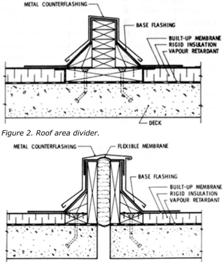
Figure 2. Roof area divider.
Figure 3. Expansion joint.
The roof area divider (Figure 2), as the name implies, is used to break up irregular roof shapes into more manageable rectangular areas. The separation between areas should be as complete as possible, with wood nailers firmly attached to the deck and surmounted by a wooden curb high enough to allow the installation of cant strips and bituminous flashings. If a vapour barrier is used it should extend under the nailer and water cut-offs should be installed on either side of it to prevent water from migrating across the joint if failure should occur in an area.
A roof expansion joint (Figure 3) usually consists of two curbs erected on opposite sides of a joint in the building frame or between building components. This detail allows the membrane to be terminated some distance above the roof level, although height alone should not be relied upon to provide water tightness and a flexible membrane should be incorporated in the joint. Expansion joints should not be restricted to building expansion joints but should be used wherever differential movement, either horizontal or vertical, can take place between roof deck components or roof and vertical surfaces.
Dividing a Roof
Division of a roof into smaller areas requires careful analysis of the structure, the roof plan, and the drainage system. Among the factors to be considered are: type of framing and roof deck and their anticipated deflections; shape of building, penetrations through the roof and changes of level; and drainage areas, slopes to drains and location of drains.
In addition, specific items often require special attention: 1) End rotation of simply supported beams and trusses can impose large strains on a membrane if the member deflects under load. 2) Re-entrant corners may impose a concentrated load on the membrane large enough to initiate splitting. 3) Roof dividers or expansion joints should not be installed either at the bottom or part way up a sloping roof, but at the highest point of the slope.
Ideally, a roof should be divided into square or rectangular areas, using roof area dividers or roof expansion joints. The membrane should be extended by means of bituminous felt flashings or flexible sheet material to form a continuous waterproof seal over the joints so that water backed up by ice and snow cannot find its way into the building.
Typical Use of Joints
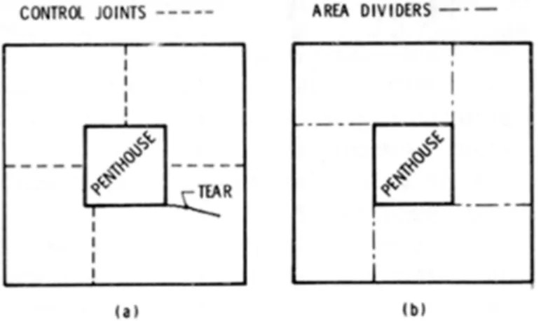
Example 1. Following repeated instances of water infiltration on a roof approximately 44 by 51 m, a tear more than 6 m long was found in the lower roof membrane, which was interrupted at the centre by a penthouse. The membrane was divided by membrane control joints (Figure 4(a)). The tear did not coincide with a joint in the insulation, nor did it form a straight line. It had started at one corner of the penthouse, probably caused by the difference in restraint on the part of the membrane ending at the penthouse wall and that extending past the corner to the control joint. A large stress developed at the point of change in roof shape, and a control joint some distance away from the corner was not effective in preventing failure.
Figure 4. Roof plan.
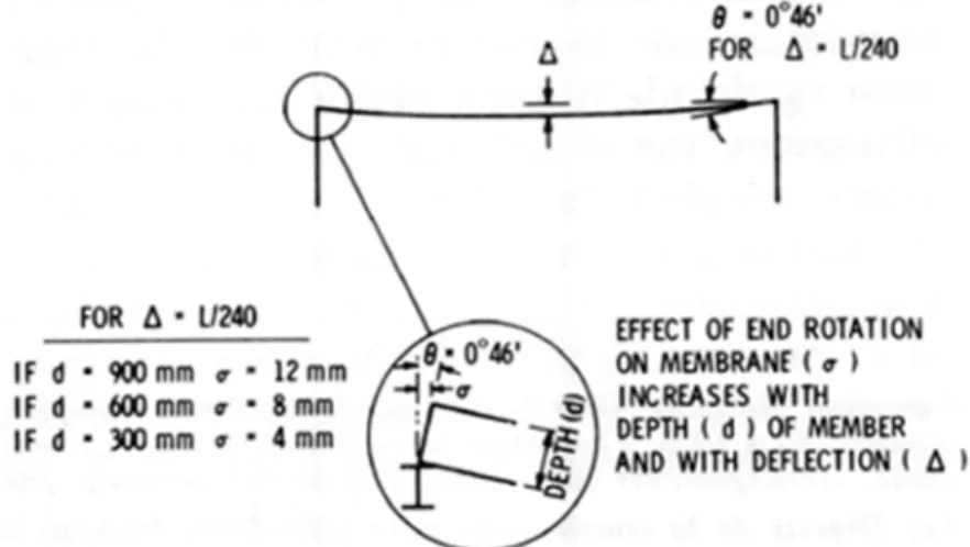
A better solution would have substituted roof area dividers (Figure 2) for control joints and located them so as to form a continuous line with the penthouse walls, dividing the roof into four rectangular areas (Figure 4(b)). The membrane edge condition would have remained the same throughout, eliminating the higher stresses often associated with re-entrant corners. Example 2. End rotation of simply supported deep beams or deck units can impose large strains on a membrane. A live load deflection of 1/240th of the span rotates a structural member at its supports through 0 deg 46 min. The horizontal displacement of the top flange is then
proportional to the depth of the member (Figure 5). If two identical members, butted over a support, deflect the same amount, the strain will be double that shown. It can be reduced by limiting the deflection or reducing the depth of roof member at its support. If the strain cannot be reduced in this manner, then an expansion joint should be used.
Figure 5. Elastic deflection on simply supported member.
Conclusion
Membrane control joints are a possible source of problems, contributing nothing to the
performance of a roofing membrane, and should not be used in conventional roofing. If there is need to break up a roof area, area dividers should be specified and, in certain cases, expansion joints used so as not to subject the membrane to possible differential movement between adjacent deck members. Uniform and adequate attachment to the structural deck is necessary if a membrane is to be prevented from shrinking. Nailing the membrane to wood blockings anchored to the structural deck at all roof edges, openings and joints is also recommended.
References
1. Solvason, K. R., and G. O. Handegord. Ridging, Shrinkage and Splitting of Built-up Roofing Membranes, National Research Council of Canada, Division of Building Research, BR Note 112, June 1976.