Common Global Architecture Applied to Automobile
Electrical Distribution Systems
by
Marcia E. Azpeitia Camacho
B.S. Mechanical and Electrical Systems Engineering (2003) Universidad Anahuac
Submitted to the System Design and Management Program in Partial Fulfillment of the Requirements for the Degree of
ARCHIVES
Master of Science in Engineering and ManagementMASSACHUSETTS INST~TiUTE OF TECHNOLOGY
atthe
JUN
16
2010
Massachusetts Institute of TechnologyLIBRARIES
January 2010
@ 2010 Marcia E. Azpeitia. All rights reserved
The author hereby grants to MIT permission to reproduce and to distribute publicly paper and electronic copies of this thesis document in whole or in part in any medium now known or hereafter created.
Signature of Author
System Design and Management Program January, 2010
Certified by
John M. Grace
Industry Co-Directo
System
Dsign and Management ProgramThesis Supervisor
Accepted by
A p bjPatrick C. Hale
Senior Lecturer, Engineering Systems Division Director, System Design and Management Program
Common Global Architecture Applied to Automobile
Electrical Distribution Systems
by
Marcia E. Azpeitia Camacho
Submitted to the System Design and Management Program on January 28th, 2010 in Partial Fulfillment of the Requirements for the Degree of
Master of Science in Engineering and Management
Abstract
Electrical and electronic components have a prominent role in today's vehicles. Particularly during the last two decades, functionality has been added at an exponential rate, resulting in increased complexity, especially of the Electrical Distribution System (EDS), which is the backbone of the Electrical and Electronic System (EES).
Increased content and complexity of electrical systems, together with pressure to reduce the design cycle time - to bring a larger variety of products to the market and at a faster pace - are forcing car companies to re-evaluate their existing electrical development processes. One of the ways that car makers have devised to accomplish this is a common EES architecture strategy, which consists in combining communization, standardization, reusability and best practices to create flexible EES architectural concepts that will be used in a higher number of derivative vehicles. This common architecture has several benefits, the most important being: reduction of development costs and time, which translates in less time for putting the products in the market; architecture, concepts and components reuse; rapid platform modifications, to adapt to market changes and regional preferences.
The EES architecture choice for a vehicle is the result of the implementation of the desired functions in hardware and software. Many considerations need to be taken into account: costs, network capabilities, modularity, manufacturing, energy management, weight, among several others. The present work aims to explain these considerations, as well as the elements of the common EES, and in particular their impact on the EDS.
Another important aspect for the successful implementation of the common architecture is the EDS development process. Despite the availability of a wide range of software tools, the current EDS approach is intensely manual, relying on design experts to define and maintain the interrelationships and complexities of the core design definition. There is a need to redefine the process, from concept to manufacture using a systems engineering approach, which would yield key benefits, like shorten development time, produce accurate harness manufacturing prints, reduce wiring costs by synchronizing all input and output data. An analysis of the tools and methods for design and validation of wire harnesses will be presented in the last two chapters of this thesis.
Thesis Supervisor: John M. Grace
Acknowledgements
This thesis represents the conclusion of an exciting journey of two years. Being part of the System Design and Management Program has been a life-changing experience, not only from the academic and professional perspectives, but also from the personal standpoint. Therefore, I would like to say thanks to everybody at SDM for this opportunity. Faculty and staff have been instrumental in my learning and development.
Especially, I want to thank my advisor, John Grace, whose guidance and insightful comments helped me improve this work to the greatest detail. His academic and industrial knowledge facilitated to stay focused on the core aspects of each topic.
I would also like to thank my sponsors, Ford Motor Company and Conacyt, for giving me the chance
to attend MIT. I truly appreciate the help that Flavio provided for this thesis and also at many other occasions. He contributed to this thesis by making me think out of the box and by keeping it on track.
I would like to say thanks to all of those who directly or indirectly contributed to this work and to
my professional development throughout this time. Thank you to my colleagues at work, whose invaluable experience and time made me grow as engineer. I am truly thankful to my student cohort, for providing me with different perspectives that enriched my academic experience and for
contributing to make this time exceptionally enjoyable.
I am thankful to my friends in Mexico, and to the friends that I made here, for motivating me to keep
going and helping me during this time. I would like to extend special recognition to Antonio, whose friendship and constant encouragement helped me sort out all kinds of challenges and made the fun times even funnier. Also, I want to say thanks to Beau, my best friend, for inspiring me and supporting me all along the way.
Finally, I would like to dedicate this work to my mom and brother. Mom, thanks for your love, for always encouraging me to pursue my dreams and for supporting every decision I have made. Eliel, thanks for listening and cheering me up from the distance.
Table of Contents
LIST OF FIGURES ... 10 LIST OF ACRONYM S ... 11 1 INTRODUCTION ... 13 1.1 M OTIVATION...13 1.2 OBJECTIVES...141.3 RESEARCH M ETHOD AND APPROACH ... ... 15
1.4 TIMELINE ...-- 16
2 VEHICLE ELECTRICAL AND ELECTRONIC SYSTEMS... 17
2.1 PRODUCT DEVELOPMENT PROCESS...17
2.2 VEHICLE SYSTEMS AND SUBSYSTEMS... 18
2.3 VEHICLE ELECTRICAL AND ELECTRONIC SYSTEM ... 21
2.4 ELECTRICAL AND ELECTRONIC SYSTEMS DEPARTMENT STRUCTURE...24
3 COM M ON ELECTRICAL ARCH ITECTURE ... 28
3.1 DESCRIPTION AND OBJECTIVE...28
3.2 COMMON ARCHITECTURE ... 29
3.2.1 Definition...29
3.2.2 EES Architecture Design Approach ... 31
3.3 DESIGN CONSIDERATIONS...33
3.3.1 Market Wants and Brand DNA... 34
3.3.2 Cost and Tim ing ... 34
3.3.3 M anufacturing and Assem bly... 36
3.3.4 Flexibility and Scalability ... 36
3.3.5 W eight... 37
3.3.6 Quality, Reliability and Serviceability ... 38
3.3.7 Industry Standards ... 39
3.3.8 Brand Im age ... 39
3.3.9 Functional Classification ... 39
3.3.10 Option Take Rates, Bundling and Volum es ... 40
3.3.12 Centralized and Hardw ired ... 41
3.3.13 Functional Isolation...41
3.3.15 Vehicle Classification ... 42
3.3.16 Vehicle Hom ologation...43
3.4 ELEMENTS OF THE ELECTRICAL AND ELECTRONIC SYSTEM ARCHITECTURE...43
3.4.1 Hardw are and Softw are ... 44
3.4.2 Feature Partitioning and Integration ... .... 45
3.4.3 Network Communications and Diagnostics... ... .... 45
3.4.4 Power Generation, Storage and Energy Management ... 47
3.4.5 Power and Signal Distribution ... ... 48
3.4.6 Fusing and Grounding ... 49
3.4.7 EDS Routing & Packaging ... 50
3.4.8 Packaging of Other Com ponents ... 50
3.5 VALIDATION OF THE EES...50
3.6 REUSABILITY...54
3.6.1 Architecture Reuse...54
3.6.2 Design Solution Reuse ... 55
3.6.3 Detail Design Reuse... 55
3.6.4 Com ponent Reuse... 56
4 ELECTRICAL DISTRIBUTION SYSTEM ARCHITECTURE ... 60
4.1 DESCRIPTION AND OBJECTIVE...60
4.2 W IRE HARNESS DEVELOPMENT ... 61
4.3 DESIGN CONSIDERATIONS...63
4.3.1 Overall EES Architecture Definition ... ... 64
4.3.2 Electrical Subsystem Mechanizations ... .... 64
4.3.3 Pow er Distribution and Circuit Protection Schem e... 65
4.3.3 Distribution Box Requirem ents ... 67
4.3.5 Connector Requirem ents ... 67
4.3.6 Serial Data Links...69
4.3.7 Ground Design...69
4.3.8 Cable Sizing ... 70
4.3.9 W ire Harness W eight ... 71
4.4 M ANUFACTURING CONSIDERATIONS... ... ... ... 75
4.4.1 Wire Cutting and Terminating ... .... 75
4.4.2 Harness Assem bly ... 75
4.5 HARNESS INSTALLATION CONSIDERATIONS ... ... 76
4.5.1 M ethod ... 77
4.5.2 Training...77
4.5.3 VisualAids ... 77
4.5.4 M aterial Handling ... 78
4.6 ELECTRICAL DESIGN PROCESS...79
4.6.1 Logical Electrical Diagram s ... 79
4.6.2 Topology Definition ... 80
4.6.3 3D CAD W ire Harness Design ... 82
4.6.4 2D M anufacturing Draw ings... 82
4.6.5 Harness Installation Draw ings... 82
4.6.6 Physical Electrical Diagram s... 83
4.6.7 CA E Validation ... 83
4.6.8 EDS Design Process CPM Analysis ... 84
4.6.9 Electrical Design Process Integration Challenges ... 87
4.6.10 Recom m endations... 89
5 EDS VALIDATION M ETH O DS...93
5.1 EDS VALIDATION AND VERIFICATION ... ... ... ... 93
5.1.1 Failure M ode EffectAnalysis ... 94
5.1.2 Failure M ode Electrical Test... 95
5.2 BREADBOARD TESTING ... 95
5.2.1 EDS Validation ... 95
5.2.2 Radio Frequency Interference ... .... 96
5.2.3 Hardw are in the Loop...97
5.3 OTHER VALIDATION M ETHODS... 98
5.3.1 CAE Testing ... 98
5.3.2 Vehicle Functional Test... 98
6 CONCLUSIONS...99
6.1 SUMMARY ... 99
6.2 REFLECTIONS...100
6.3 FUTURE EDS DEVELOPMENT ... 101
6.4 FURTHER RESEARCH ... 102
7 APPENDICES...103
APPENDIX A EDS DESIGN PROCESS WORK BREAKDOWN STRUCTURE ... ... 103
APPENDIX B PERT CHARTS FOR CMP ANALYSIS - CHART 1 ... ... 108
APPENDIX C PERT CHARTS FOR CM P ANALYSIS - CHART 2 ... 109 APPENDIX D PERT CHARTS FOR CM P ANALYSIS - CHART 3 ... 1 10
BIBLIOGRAPHY ... 111 ENDNOTES...113
List of Figures
1- Figure 1.4.1 2- Figure 2.1.1 3- Figure 2.2.1 4- Figure 2.2.4 5- Figure 2.3.1 6-Figure 2.4.1 7- Figure 2.4.2 8-Figure 3.2.2 9- Figure 3.2.3 10- Figure 3.2.4 11- Figure 3.3.15 12- Figure 3.4.1 13- Figure 3.4.4 14- Figure 4.4.1 15- Figure 4.2.2 16- Figure 4.3.3 17- Figure 4.3.8 18- Figure 4.5.3 19 -Figure 4.6.1 20- Figure 4.6.8 Thesis Timeline ... 16Product Development Process ... 17
Vehicle Systems ... 20
Systems Engineering V Diagram...21
Boundary Diagram ... 23
Dilemma in Product Development Organization ... 24
EES Matrix Organization...27
Levels of EES Architecture ... 30
Basic Car Electrical System...32
Balancing Architectural Alternatives ... 33
Example of Tested Items for Homologation...43
EES Architecture Elements ... 44
Service Centric Software Architecture ... 48
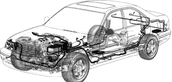
Basic Car Electrical System: Layout of Volga GAZ-2110... 60
Example of Electrical Architecture Commonization... 62
Vehicle Fusing Assessment Matrix...66
3D View of Harness, Connectors and Attachment Points (Vehicle Position)...74
Visual Aid Example: Harness Routing Installation Process Drawing ... 78
Electrical Distribution System Design Process Flow Diagram ... 81
List of Acronyms
2D Two-Dimensional
3D Three-Dimensional
ABS Anti-lock Braking System
AMIC Automotive Multimedia Interface Collaboration
BCI Bulk Current injection
BSM Blind Spot Monitor
CAD Computed-Aided Design
CAE Computed-Aided Engineering
CAFE Corporate Average Fuel Economy
CAN Controller Area Network
CD Compact Disc
CHMSL Center High Mounted Stop Lamp
CID Centerstack Information Display
CPM Critical Path Method
CUV Crossover Utility Vehicle
DFMEA Design Failure Mode Effect Analysis
FMET Failure Mode Electrical Test
DNA Deoxyribonucleic Acid
DRL Daytime Running Lights
DTC Diagnostic Trouble Code
DV Design Verification
DVD Digital Versatile Disc
ECU Electronic Control Unit
EDS Electrical Distribution System
EES Electrical and Electronic System
EMC Electromagnetic Compatibility
EOL End-of-Line
FFC Flexible Flat Cable
FPC Flexible Printed Circuit
FSS Full Service Supplier
HIL Hardware In the Loop
HMI Human-Machine Interface
HS-CAN High-Speed CAN
HUD Heads-Up Display
1/O
Inputs / OutputsIVD Interactive Vehicle Dynamics
IVHS Intelligent Vehicle Highway Systems
MCAD Mechanical Computer-Aided Design
MS-CAN Medium-Speed CAN
NVH Noise, Vibration and Harshness
OEM Original Equipment Manufacturer
PCM Powertrain Control Module
PDB Power Distribution Box
PERT Program Evaluation Review Technique
PV Process Validation
RCM Restraints Control System
RKE Remote Keyless Entry
SAE Society of Automotive Engineers
SIL Software in the Loop
SPC Statistical Process Control
SJB Smart Junction Box
TPMS Tire Pressure Monitoring System
RF Radio Frequency
1
Introduction
1.1
Motivation
Electrical and electronic components have a prominent role in today's vehicle performance and customer appeal. More than half of the comfort and convenience features that are available in a modern car today were simply not around ten years ago, while other features were only available in premium or luxury cars. For example, features like electric windows and seats, air bags and remote door opening are standard in most vehicles produced today for the U.S. market, while other systems like vehicle navigation, remote keyless entry and tire pressure monitoring are all becoming very popular and less expensive, making them attractive for the average car buyer.
These innovations make the interaction of the customer with the car more pleasant, but they also represent an advantage from the safety and reliability perspectives. Cars are safer because of the addition of innovations such as the restraints control module, which commands the deployment of the airbags and cuts the fuel flow to the engine when an accident occurs. The same way, cars are more reliable because of electric components like the traction control or the interactive vehicle dynamics modules, which helps the vehicle adapts to varying road and driving conditions. Therefore, competition among car makers is focusing highly on offering more customization options, in-vehicle electronics compatibility and safety features, all of which are to help keep passengers entertained and safe, as well as to enhance the customer-vehicle experience. Of course, these factors pose challenges that the automobile manufacturers must resolve in order to keep themselves at the top of their game in satisfying the rapidly evolving consumer demands.
One of the biggest challenges is the increase in wire content, which has the inevitable components of cost and weight increase, both acting in detriment of the car's performance and price competitiveness. Everything, from controlling the engine functionality to providing safety through the restraint systems, interacts with the Electrical Distribution System (EDS), so it is no surprise that this is one of the fastest growing systems within a car. For instance, the new modern automobile possesses up to 2 km of wire and nearly 2000 terminals, compared with the vehicles of the 1950s which had only 100 terminals and 75 meters of wire'. In fact, electronics constitutes approximately 35% of the content and cost of today's average vehicle, and the percentage is even higher for luxury vehicles. As a consequence, the modern vehicle electrical system is becoming more and more complicated.
This massive electrification of the car has forced automobile makers to commonize and standardize at all levels: system, subsystem, part and component. However, the optimal solution should be developed at a higher level. Until now, electrical architectures had differed amongst the regional organizations around the world due to a lack of a global EES engineering standard, which makes it extremely difficult to optimize material and intellectual resources; thereby, deriving in the inability to migrate features back and forth or source at higher volumes.
One of the initiatives that has been devised to address these concerns is the creation of a common electrical architecture strategy, which will be explained in greater detail in one of the chapters of this thesis. This strategy emerged as an effort to commonize architectural elements to enable various levels of sharing between regional organizations, as well as reduction of engineering development costs. The strategy only defines the elements that need to be common, but does not define the entire architecture. Not only will this common electrical architecture help reduce costs
by taking advantage of the economies of scale, but it will also promote communication among the
regional organizations, facilitating the exchange of knowledge. Nevertheless, this huge modularization has some disadvantages, because it decreases flexibility between different hardware and software strategies, hindering the development of more ad-hoc systems according to the market needs and demands.
A clear understanding of how this new common electrical architecture strategy works in an
electrical and electronics systems engineering organization is a crucial element in identifying its specific implications for the EDS. This understanding will make it possible to realize the current and future needs from the design, manufacturing and validation perspectives, as well as other factors that are crucial for its successful implementation.
1.2 Objectives
Since first instated in automotive Original Equipment Manufacturers (OEMs), common electrical architecture guidelines have proved to be a very effective way to communicate and drive the design of electrical and electronic components within the electrical systems engineering division, and it is currently seen as an innovative way to shift into the future as car manufacturers become global organizations and as their product development divisions around the world begin collaborating more closely together.
However, there are still many challenges that need to be addressed in order to have a comprehensible, coherent and holistic process for the design of electrical distribution systems. By analyzing the most important factors, from the EES and EDS architecture perspective, this thesis
intends to:
e Serve as a basis for understanding the current electrical architecture elements, EDS development processes and the role of the current validation methods;
* Identify the shortcomings or limitations, if any, in the existing EDS architectural design process, and suggest improvements on the recommendation section;
* To use a systems engineering approach to categorize the current engineering challenges that the architectural strategy poses, and identify potential issues that will emerge when
By creating a sketch of the current system's hierarchy, it will be possible to define the EES
boundaries and recognize the interactions with other systems. A Critical Path map will help to pinpoint the critical tasks within the EDS design process which have the greatest influence for achieving the deliverables throughout the development phases. This should be done along with the architectural concept analysis, to create a complete panorama of all the relevant aspects and interactions within the wire harness development process.
1.3 Research Method and Approach
Research will be conducted by an Electrical and Electronics Systems Engineer who works for two distinct regional organizations. With the purpose of gaining insight of how the electrical distribution system engineering development process currently works, it is essential to look at it from the perspective of the internal stakeholders.
Specific information will be collected through literature research on the common electrical architecture strategy, EDS and electrical/electronic systems processes, global product development process, plus the latest tendencies in other automotive OEMs. A deep dive into the existing System Engineering literature will be carried out with the aim of identifying the fundamental elements that are present in the current EDS design process and practices, and recognizing those principles that have not yet been put into practice and that would benefit the regional organizations.
1.4 Timeline
Thesis topic selection
Thesis Proposal creation ln
Thesis Proposal submission & approval
Outline definition
Literature Research
EESE and CGEA explanation
Characteristics of the Architecture Wire Harness Development Validation Methods Data Analysis
Recommendations and conclusions l
Introduction section
Final ist draft due and corrections
Final 2nd draft due and corrections Thesis submission
W- Figure 1.4.1 Thesis Timeline
2
Vehicle Electrical and Electronic Systems
"A system is a network of interdependent components that work together to try to
accomplish the aim of the system. A system must have an aim. Without an aim, there is
no system."
Dr. W Edwards
The primary objective of this chapter is to present an overview of some of the concepts that are
relevant to understanding the vehicle subsystems in a car, their main characteristics and how they
interact with the Electrical and Electronic System (EES) through the wiring, which is the main
subject of study of this thesis.
2.1 Product Development Process
Like most product development projects, the product development process at the automotive OEMs
consists of sequential phases. It includes the general phases of definition, design, development,
validation and launch. Nearly all activities of the organization are part of the vehicle development,
which makes it an interdisciplinary activity requiring contributions primarily from Marketing,
Finance, Design, Manufacturing and Purchasing. The product development process essentially
consists of six phases as shown in Figure 2.1.1.
2- Figure 2.1.1 Product Development Process2
During the Planning phase, product development opportunities are identified by various sources,
including marketing, research, customers, current product development teams, and benchmarking
of competitors. The OEM looks at these opportunities from marketing, design, financial and
manufacturing
standpoints,
analyzes
the
business
case,
value
proposals,
market
targets/segmentation, and decides which opportunities should be explored. During the Concept
Development, these ideas are evaluated taking into consideration the customer, corporate,
governmental, and social needs. The production feasibility is also assessed at this time. During the
System Level Design phase, the product architecture is generated and the product is decomposed
and its various systems/components are assigned to the respective technology teams. The key suppliers are also identified during this time. In the Detail Design phase the complete specification of all the parts in the product as well as all the parts are identified. The Testing and Refinement phase entails the construction of multiple pre-production versions of the product, or prototypes. These prototypes undergo reliability testing, life testing, and performance testing during this phase. In the Production Ramp-up phase the operation of the entire production and manufacturing system begins.
In order to execute the vehicle programs in a timely manner, the project management team defines
gateways or milestones which are also used to assess the status of the project. For the vehicle
program to move from one phase to the next, all aspects of the system must achieve a common level of readiness at the same time. Even when the systems and subsystems individually have separate timing requirements for certain gateways, they will have to meet the ultimate timing for the
program collectively.
2.2 Vehicle Systems and Subsystems
A vehicle can be thought of as a system. On the largest scale, the inputs are the target market
customer's wants and needs, business needs, and government regulations. The product development process consists of all the activities that occur at the automotive OEM to create a vehicle from these inputs. The output is information, in the form of engineering drawings,
specifications and other design/manufacturing guidelines that will be transferred to the responsible areas for building the vehicle that the customer purchases. Engineering a competitive product in the current dynamic and changing market is a challenge that requires an organized systematic approach focusing on the whole.
The overall vehicle behavior depends upon several and sometimes complicated interactions between the numerous elements that comprise it. At the end, they all come together to deliver a
the interactions and interfaces between the various components is essential to creating exciting products that will satisfy the needs of the customers with the least number of defects.
One of the ways to reduce the complexity when dealing with such a big system is partitioning, which is the process of hierarchically decomposing or dividing the vehicle into elements based on
one or more criteria. The reasons for partitioning vehicles are mainly:
a) To organize a complex system in a way that can be understood and managed.
b) To focus the teams on comprehensible, lower-scope project objectives.
In the automotive lingo, 'vehicle level' is a term used to define tasks or attributes that can only be carried out or applied with reference to a whole vehicle. For instance, ride and handling, noise, vibration and harshness (NVH), durability, and craftsmanship, are all vehicle level attributes since they apply to and can only be assessed with a whole vehicle. Vehicle level engineering is concerned with building and verifying characteristics of the whole vehicle such as interior lighting harmony, exterior and interior style themes, acoustics, etc.
People within the automotive industry utilize the concept of 'system' to refer to a set of connected parts or elements within the vehicle that share common attributes and can be characterized in some way. Within automotive OEMs the partitioning of the vehicle into systems has been carried out mainly by the grouping together of functions. The highest levels subdivision in which the total vehicle can be partitioned into are the following five vehicle systems: Body, Electrical, Powertrain, Climate Control, and Chassis.
Figure 2.2.1 represents a real world example of vehicle partitioning or high level subdivision in systems and subsystems of the vehicle. As explained by Flower3, the term 'Body system' is used as a system level partitioning to describe those elements of the vehicle that are typically structural, static, and are related to the exterior and interior styling of the vehicle, like body panels, trim, instrument panels and sheet metal. In the same way, the term 'Electrical system'is used as a system level partitioning to describe those elements of the vehicle that use electrical/electronic power and information technology, like relays, electronic modules, and batteries. 'Powertrain system'is used as a system level partitioning to describe those elements of the vehicle that are involved with providing automotive power to make the vehicle move, like the engine and transmission. In the case of the 'Climate Control system', it is comprised by those elements that serve to control heating,
ventilating and air conditioning, with the purpose of providing environmental comfort inside the cabin. Finally, the term 'Chassis system' is used to denote the elements that bring support to the car, where all other elements fasten to, like the frame and suspension, which also to provide steering, shock absorption and smooth handling.
1
1
SYSTEM LEVEL 1 SUBSYSTEM LEVEL 2 SUBSYSTEMEl
I
-- -A ---START'
m
3- Figure 2.2.1 Vehicle SystemsThe term 'subsystem' is used to mean those smaller elements of the system that can be broken further down into another characteristic. Normally the characteristic that is used is the function that the entire group of interconnected components is aiming to provide. A typical example of a small electrical sub-system is the power supply subsystem. This is a part of the electrical system, but remains a smaller system in its own right, for the reason that it consists of a group of components all working together to provide two discrete functions: starting and charging. Hence, it is a system that is below a system level partitioning and therefore is denoted as a subsystem that now can be broken down even further into constituent components such as alternator, starter motor, battery, current sensors, wires, etc.
The idea of breaking the vehicle down into subsequent smaller systems is considered to best enable the customer wants and needs to be cascaded downwards from high level vehicle requirements to detailed components requirements. Once this is completed, OEMs use the process model illustrated in Figure 2.2.1 below that shows the engineering V - the cascade of customer wants to component design - to help visualize the aspects of the design that are being developed and when they are being developed. I CA I r- - - - -r- - -PO; St"P I 6Li;:
:-,in
CO-NTROLC IA NI XTFERIJIL 'fT*f Azy CITRRUNT
In concept, the engineering V model takes the timeline of the specific system development plan, and
folds it into a "V" shape at the point of product realization. It acknowledges that information
relevant to the completion of the later test phases is derived from the earlier development phases
and aligns these to show relevant information flows.
ENG GPERATION&
MANAGEMENT MNNAC
CONCE-PT OF SYSTEM VALIDATION PLAN SYSTEM
OPERAIONSVALITIMEN
SYSTEMLEVEL SYSTEM VERIFICATIONgPLAN SYSTEM
REQUIREMENS VER1ICATION
SUBSYSTEM
SUB3SYSTE VERIFICATION
\REQUIEMENTS
_PLAN SUBSYSTELDESIGN COMPONENT
\
VERIFICATIONCOMPONENT PROCEDURE COPNT
DE TAILED VRFCTO
DESIGN
IMPLEMENT ATION
HARDWARE & SOFTWARE 0f
TRACEABILITY
TIAU
4- Figure 2.2.4 Systems Engineering V Diagram4
2.3 Vehicle Electrical and Electronic System
The vehicle's EES, which is the foundation of this study, is the brains and nervous system of an automobile. In its early days, the electrical system in a car was comprised of only basic wiring
technologies that were almost exclusively used for distributing power to a few parts of the vehicle:
ignition system and interior/exterior lighting components. Over the years, the EES has gradually
evolved and nowadays, it includes all sorts of sensors (mechanical, optical, pressure, temperature,
current etc.), actuators (hydraulic, stepper motors), switches, relays, Electronic Control Units
(ECU), among other components. These electrical and electronic components interface with all the
other systems in a car.
The scope the EES, as defined by automotive OEM's program management team, comprises
components and subsystems designed and released by the EES department, including shared
signals, network messages, link based diagnostics, electromagnetic compatibility (EMC), and the
vehicle EES architecture. The EES interfaces with the other systems as shown in Figure 2.3.1. With added customer wanted features like drive-by-wire, traction control, tire pressure monitoring system, reverse park aid, navigation system, infotainment system, and active anti-theft system, it is evident that there is a high level of interaction between the EES with all the other systems in the vehicle. This generic boundary diagram serves to demonstrate the extent of the EES and the most important factors that affect it. This is a generic version that can be adapted to reflect the program specific electrical/electronic content, features and design implementation strategies.
The EES is partitioned into the following subsystems, some of which will be described in succeeding chapters:
* Power Distribution * Power Supply
* Powertrain Engine Control e Transmission Control " Exterior Lighting * Interior Lighting * Visibility " Horn " Restraints
* Interactive Vehicle Dynamics (IVD)
" Driver Information and Warnings
* Climate Control
e Power Convenience Electronics e Security
* Infotainment and Multimedia
e Intelligent Vehicle Highway Systems (IVHS)
e Communications/Telematics
e Navigation Systems * Special Vehicle Features
,4tsgi baiter AnttennI Other Vehicip Ssems.
Warnings & Buzzer Speerss.
inoalocgn Radio Noise Suppression
W ndud Information
Environment Environmental
chmial, salt L=p4ashr
S cNat sel: 1Pets Conditions
Mesag Centeri ntenay Other Vehicle Systemt
tlt ctionc InuedteiBL-Satery ReadirNosupp A rterestor - - Information Climate Control SystmOterVeileSytes olator vluaton InucdMultiple Function Electronic ControlStrrMor
icto mnachcuW , 5101 h Conitions Electronic Features Module Poveedrain $ystem
Anc sThcWarningsPowertrain Mechanical Engine
Remote Conve e Eleccal Distribution 4- Energy 0rivellne Vehicle Route GuldanceiNavigation Wring & Circuit Protection
Vehicle Emergency Messaging Power Olstrutb Boxes Cutch
Keyless Vehicle FlsesExhust-Flashers
Electronic Compass Power Points & Cigar Lighters Mechanical Energy
Voice ControlFrm
CL Intelligent Cruise Control $uspension
v &Side Vision VehiclegIectcllectrorl taeworkkes
Trafi information Vehcl Communication Network-- Electric Power Fuel
Cabin Temperature Control Electrical Energy Management0 Interface, Steering..
& DataVehicle Electronic Diagnostics Electrarteagnetic
Compatibilty--qat /flo Eqip. Vehicle Systems Other Vehicle Functions Power lstrition
Msern Data &Restraining Device Module/Sensing Shared Circulta/Signals
iwToop Responses Tire Pressure Monitoring
Rrsaonso
Switches Connectors
neto. Electric Power
+ I
WlesConsumerPout
As a result, designing a vehicle's EES is a tremendous job with a high level of complexity. The vehicle's entire EES needs to be considered and all constraints understood in order to facilitate the cascading of the customer wants and needs accurately into the design and to create a system that achieves cost, timing and quality objectives. If the entire system is not considered, one subsystem/module may be optimized at the expense of the rest of the system, jeopardizing its intrinsic harmony. For this reason, a comprehensible interpretation of the elements that form the
EES and the interactions between these elements and the other subsystems is compulsory to
facilitate the analysis of the EDS, which is the main focus of this study.
2.4 Electrical and Electronic Systems Department Structure
Vehicle partitioning must also be consistent with the corporate structure that is responsible for delivering function. Hence, in order to reflect the functional partitioning of the vehicle electrical systems outlined previously, the automotive OEM product development organization should be structured in a similar way. There are, however, inevitable tradeoffs when deciding how to arrange any organization. Either by department or by project teams, the main question of which one best enables the exchange of information and collaboration is always present. As Professor Tom Allen explains, there are important differences between these two approaches:
Figure 2.4.1 highlights the most important characteristics of each type of organization. It condenses the options and tradeoffs that every management team in any organization faces when setting the foundation for a new department or whenever re-organization of the current department is needed. In many cases, engineering organizations fall somewhere between the fully departmental and pure project team, or are a mix of these two.
Within the EES organization, the engineering process is deployed at all levels using a matrix management structure to balance the functional and project requirements of the product development process. The EES matrix structure is shown in Figure 2.4.2, which represents the high level EES organizational charts. All chief engineers report to the EES director, who is the most highly ranked employee within the EES organization. It can be seen from this diagram that there are four chief engineers: one of them is responsible for the application and integration of technologies in specific projects or programs, while the other three are in charge of the technology departments. The program groups are divided by the size of the vehicle: small cars, medium cars, large cars, crossover utility vehicles (CUV), trucks and specialty vehicles. A manager leads each of these groups, which are further divided into platform derivatives. A supervisor responsible for integrating all electrical technologies leads each platform derivative. This high level chart lists the manager's direct reports (supervisors) but does not show each supervisor's group in detail. The program supervisor groups have been listed simply as 'SC 1' (small car 1), 'MC2' (medium car 2), 'TR3' (truck program 3), and so forth.
The technology groups are divided in a way that resembles more the EES partitioning: power supply, body and security modules, audio, infotainment, climate control, power distribution, etc. Just as in the case of the program groups, technology groups are led by a manager, who is responsible for various technology components and subsystems. Hence the technology groups are broken down into smaller groups, principally by type of technology, led by a supervisor. These technologies have been listed just as 'AUT5' (audio technology 5), 'CC2' (climate control technology 2), 'CN1' (connector technology 1), and so on.
It is pertinent to mention that there are other classifications within both technology and program groups that help differentiate the engineering roles. The terms system, subsystem and component (or commodity) have been described before, and simply denotes the level at which the engineer works. However, the term application engineer and core engineer, which are widely used within EES organizations, need to be defined. 'Application engineer' is used to describe an engineer delivering
or applying electrical technologies to a specific project, i.e. an engineer working for a technology group but applying the technology to a specific project. The term 'core engineer' is used to describe those engineers that do not work on specific projects but work across all car lines ensuring that the applications of electrical systems and subsystems are controlled and that lessons learned are carried across all projects. For some larger or more technical groups the post of technical specialist is also used to control core technology. This position is a lower-lever management position designed to keep highly skilled engineers within certain teams.
A matrix organizational method of this kind has clearly several advantages over organizing purely by department or by project. Instead of working in isolated groups, this kind of organization allows
team members to exchange specialized knowledge, best practices and lessons learned across groups. For instance, we can think of the case of a cluster applications engineer who is assigned to different programs and reports to a cluster technology supervisor. This engineer must interact with the core cluster engineer to understand the functionality of the component, which also helps him/her to be aware of how new technologies develop. Besides, the cluster applications engineer must work closely with the applications electrical systems engineer and the network communications engineer for each of the programs to make sure that the cluster is electrically compatible with the rest of the system and to add the cluster-specific messages to each program's configuration specification and message's list. As we can see, the cluster engineer works indirectly under several managers to get his/her job done. This allows him/her to take into account the interdependencies in project work. This has the advantage that the engineer gains in depth knowledge of his component, but on the other hand sometimes he/she can be under al lot of pressure because of prioritization discrepancies between managers. However, this disadvantage can be minimized with a properly managed cooperative environment.
AF
7- Figure 2.4.2 EES Matrix Organization
....
3
Common Electrical Architecture
"Architecture depends on Order, Eurhythmy, Symmetry, Propriety, and Economy." Vitruvius Pollio [The Ten Books on Architecture]
3.1
Description and Objective
Like in almost any other industrial sector, competition among automobile makers has gotten tougher and tougher as customers demand better products at a competitive value. Hence, automobile companies are launching new vehicle models which meet the consumer preferences in various niches for their numerous products all around the globe. As a result, developing different vehicles simultaneously is a must for car manufacturers, but doing so may lead to increased production costs in case no appropriate development, cost and launching strategies are applied. To avoid this scenario, the common platform strategyi has been in use by car makers for decades and has promoted both standardization and reuse of vehicle components and systems. In consequence, common platforms represent an advantage from a couple of standpoints:
* Reduction of the overall project cost by purchasing large scale volumes of shared components and systems.
* Reduction of the overall project lead-time by keeping a base platform and making the changes/upgrades required by the specific vehicle line, maintaining a high level of commonizationii among vehicle designs.
However, in recent years, a new concept in product development called common architecture strategy has emerged and has been put into practice by some of the world car makers. Through combining commonization6 and standardization, the global architecture promises to become a better option and to provide greater benefits beyond what can be accomplished by the conventional common platform strategy.
* The strategy of platform sharing is a practice that automakers have embraced with vigor which portions common design, engineering, and production efforts over a number of outwardly distinct models. Platform sharing mixes lower-volume differentiating technologies to increase market attractiveness with higher-volume standardized technologies to lower overall costs.
" The core of a platform commonization strategy is a process of finding the potentially common elements (product
and manufacturing processes) within a family of products and designing for commonization and standardization of them.
In this chapter, the implications of the implementation of the common electrical architecture will be analyzed, with the ultimate objective of identifying the relevant variables that have to be taken into consideration when selecting an appropriate strategy for developing a new global architecture for a car's EES.
3.2
Common Architecture
3.2.1 Definition
Architecture comprises the concept of the product, defined with boundaries, goals and functions
that satisfy the customer needs, meets strategic business goals and incorporates appropriate technology. Unlike platforms, architecture is sustainable, can evolve and be modified as required.22
Platforms are more specific, more rigidly defined from conception, and therefore less flexible. Car
makers recognize the word architecture as a more flexible and wider notion than the word platform due to the fact that architectures can be the base concept for a larger number of derivative concepts (either at a vehicle or system level) when compared to a platform.
One of the main differences between the application of platform and architecture is certainly the way both planning and engineering are performed in each of these strategies. In the case of the architecture, all derivative concept requirements are taken into consideration from the earliest definition phase and cascaded into the engineering development phase from the very beginning. This is not necessarily true for the platform, because the company might decide that a derivative for a new market is going to be added to the project; therefore, the requirements for this new market have to be included somehow in later phases of the development process. Subsequently, this poses serious risks to the project, like:
* Cheapening high-end products or adding unnecessary cost to lower-end ones.
* Performing costly modifications to the product to make it technologically compatible with the new market requirements.
* Changing design requirements at a late development phase multiplies the risk across numerous derivative concepts, making recalls and redesigns potentially very expensive.
Following the notions of commonality and reusability, automotive OEMs have developed electrical and electronic architectures based on their experience and their knowledge of past efficient
systems. They create numerous architecture concepts and assess them against each other. Based on
the OEM's corporate objectives and all types of requirements (functional, corporate, governmental,
environmental), they define evaluation criteria. After evaluation of all alternatives the best is
chosen for the specific application and market. This methodology worked well enough in the past,
but with today's pressure of development time and budget, OEMs are now looking for a better way
to address these issues in a global manner as the volume of electronics and in-vehicle networking
increases.
Experts have envisioned the common electrical architecture as a way to define only the elements
that need to be common, not the entire architecture. The common architecture only defines a
portion of the regional architecture just as the regional architecture defines only a portion of the
vehicle specific architecture. This is represented in Figure 3.2.2 below.
8-Figure 3.2.2 Levels of EES Architecture
The motivations that the car makers have for implementing a common architecture strategy for the
development of EES are listed next:
* Sharing a common electrical design to reduce re-engineering across platforms, brands and
applications. As discussed in Chapter 2 of this thesis, not only does the electrical system
deliver purely electrical features (audio, illumination, power windows, etc.), but it also
controls and interconnects many other features in the vehicle (anti-lock braking system
(ABS), remote start, restraints control system (RCM), tire pressure monitoring system
(TMPS), etc.).
* Mechatronics solutions have emerged, where the power that drives electronics is no longer on the ECU's main board but moved to the actuator. Similarly, signal-conditioning electronics moves adjacent to the sensor itself. This way of putting electronics in the car coincides with a strong increase in electrically-driven actuators replacing the traditional belt-mechanics. By shifting to a common architecture, automotive manufacturers and suppliers can take advantage of these new technologies to increases design flexibility.7
" Currently, electrical architectures differ between the various regional organizations, leading
to an inability to migrate features back and forth or source at higher volumes. Communization of architectural elements will enable various levels of sharing between these regional organizations, ultimately allowing to use global resources efficiently and to deliver innovation quickly at the lowest cost and best value to all regional partners.
3.2.2 EES Architecture Design Approach
When vehicle OEMs start the development of a model with major changes, they routinely have to make alterations to the vehicle structure, modifications to the internal and external sheet metal, and incorporate electrical- and electronic-based features. From a macro point of view, even though the electrical/electronic content is under development almost immediately, the structure and sheet metal aspects of the new platform are typically the primary focal point of the OEM. This non-EES focus is simply due to the history of the vehicle development process. Starting in the middle of the twentieth century, vehicle styling was the top concern of OEMs. Safety requirements brought more attention to the underlying vehicle structure starting around the 1980's. Only within the last decade has the importance of EES features as a product differentiator become prevalent.
OEM metrics vary broadly around the world. For this reason, as Turner9 explains, when performing the EES architecture analysis, a variety of specific OEM EES requirements may need to be balanced. In some cases, cost is the primary driving factor. Many other times, the impact of weight, packaging, and reliability may be critical metrics in addition to the cost metric. Finding the correct balance for the particular OEM is critical. The EES architecture must be correctly balanced based on the design direction data gathered early in the vehicle development process. As the vehicle design progresses,
this same EES architecture must be able to continue to evolve and adapt throughout the
development process according to updated design information.
9- Figure 3.2.3 Basic Car Electrical System8
Figure 3.2.4 serves as an example of how various elements that define the EES architecture are
combined generating an EES system cost metric curve for multiple architecture solutions. While the
knee of the curve indicates the optimal solution, it should be noted that this is a single point in time
analysis. In reality, this point may not be the best solution for the OEM when looking at the long
term plans for the vehicle platform. Consideration for future expansion of features may require a
different point on the curve to be selected.
With the growing importance and sophistication of electronic features in a vehicle, the early
definition of an EES architecture that balances all elements and critical design factors is required to
achieve the optimal, lowest cost design.
WINDOW OF MODERN ElE ARCHITECTURES
10
ckaing
Electrical
classic, less complex - modern, flexible POSSIBLE architecture architecture ARCHITECTURES
HIGH DEGREE OF DISTRIBUTED
INTEGRATION SYSTEMS
MOST COST-EFFECTIVE ARCHITECTURE
10- Figure 3.2.4Balancing Architectural Alternatives9
3.3
Design Considerations
There are a number of factors that come into play when determining a vehicle's electrical
architecture and partitioning of its EES. Design constraints are additional constraints on a specific
design that are less formal in nature. These can be derived from business needs, corporate
initiatives (e.g. commonality) and recognized best practices which are thought of as de facto
standards. The typical constraints that affect the vehicles EES architectural components can be
anything from allocating the functions to their physical space, identifying the possible trade-offs
and complying with corporate and governmental regulations. The design constraints that have a
major impact on the vehicle's EES, including some that have been identified by Rushton and
Merchant'
0, are discussed next.
3.3.1 Market Wants and Brand DNA
Vehicles must meet local customer's requirements with a consistent feel and sound that is unmistakably that of the car manufacturer. To do this, identification of market wants is the most
important thing that OEMs must consider before determining a vehicle's balance and harmony attributes, which will ultimately define its DNAiii. The DNA11 is a set of functional attributes of a
system that are designed to be easily recognizable by the customers as a member of the OEM product family, which help ensure consistency of the brand, reinforces its character, and enhances harmony across its attributes. The goal of the car manufacturers should be to define the DNA elements which can be exactly the same globally. In a few instances it can be necessary to define
DNA elements which deliver a similar character, however, tuned to meet either local, legislative or
customer preferences. In the case of the EES, DNA elements such as the information strategy and switch functionality are relevant for the characterization of the human-machine interface (HMI) for a specific vehicle brand.
3.3.2 Cost and Timing
Like in any other industry and product development process, cost and timing are the two major factors that drive the design of a car. These will determine how much of the vehicle is carried over from the previous model year. For instance, when there is minor refreshment to the vehicle from the previous model year, minimal changes will be performed. In the case of a brand new vehicle model, major changes always occur. Whenever a program has a small budget, it is expected that it will use a lot of carry over components and modules. Although this may appear as a cost saving opportunity, it is not always the case, given that carry over components bring a lot of side issues with regard to interfaces (architecture and partitioning). Therefore, cost and cycle times play a big role in determining the architecture of the EES in the early stages of the development process.
The cost elements that occur during the phases of the EES architecture life-cycle are12:
* Design and development cost. This category encompasses the cost of developing and validating the hardware and software that is executed in embedded modules within the EES architecture. The cost items include OEM engineering activities (i.e. total system specification, documentation and validation) summed with supplier engineering activities, '" Deoxyribonucleic acid (DNA) is a nucleic acid that contains the genetic instructions used in the development and functioning of all known living organisms and some viruses.
such as design, development, and validation of the EES components and sub-systems. From the software point of view, cost is driven by items like coding, software licenses and office space (both for OEM and suppliers) - all items that are relatively independent of the architecture chosen.
" Partfabrication cost. This refers to the manufacturing cost for the parts and subsystems of
the production version of the EES architecture. The current supply chain for EES components relies almost exclusively on suppliers for fabrication. The cost items in this category include the component's cost (tooling and piece cost) and packaging cost.
*
Assembly cost This is the cost related to the integration of the parts into the vehicle during production. The EES assembly cost includes the cost associated with connecting the parts and placing them into the vehicle body. The placement cost is comprised of the cost of inserting the system into the vehicle including fastening, attachment and labor to perform the operations. In this category, the most important items are: a) part maintenance cost, which is the engineering and production effort to keep track of new part numbers, and b) plant's internal module flashing cost." In-service cost. The cost of ownership resulting from repair and/or maintenance, which includes items like re-flashing modules, replacing parts, and labor costs.
There are basically two elements that need to be considered in regards to timing:
*
Development time. This term refers to the time required to execute the new vehicle project, from its initial conceptual phase until the vehicle launch. OEMs keep shortening the development time with the aim of offering the latest technological advances and convenience options to the customers before the rest of their competitors. As a result, the lead time for developing electrical and electronic components has shrunk too, making it more challenging than ever to be ahead of the game in offering products that meet the different markets demand.*
Lifecycle. This is the time the new vehicle is kept in the market following the market trends. In the last decades, market tendencies have affected the vehicles' lifecycle, making it shorter, which requires car makers to renew their portfolios very often in order to satisfy customer wants. A vehicle's lifecycle has a direct relationship with its development strategy.In most cases, the longer the vehicle's lifecycle, the larger the amount of changes that will be required to keep its appeal during the time it stays in the market.
3.3.3 Manufacturing and Assembly
What is the impact of a jumper harness from a system point of view when compared with the help it brings to the vehicle assembly process? Is vehicle assembly time/efficiency more important than the electrical system piece price? Does changing the routing of a harness or the location of an inline connector affect the reliability of the overall EES? What are the implications with respect to cost and ease of manufacturing of changing the location of a module in the vehicle to enable the assembly plant to construct their vehicle in a modular build fashion? These are all questions a design team must answer as it develops a system or subsystem architecture solution for the vehicle. Being able to address these tradeoffs and deliver results will allow the design team to make the correct decision for the vehicle.
Manufacturing and assembly constraints can be very restrictive on the design. Attributes such as ergonomics and EMC should be taken into consideration when choosing the physical location of any component within the car. For example, the size of a transmission control module, the type and size of its electrical connector and associated circuits can be affected by the manufacturing and assembly requirements.
The need to get more products to market faster has driven manufacturers to distribute production over many, often geographically remote, plants and contract manufacturers. The strategy to "plan anywhere, build anywhere" requires technologies and methodologies that allow manufacturers to efficiently author, simulate and manage manufacturing information throughout their organization and with each other.'3 For these reasons, when designing the EES, or any other system, automotive OEMs must ensure that the design is consistent with manufacturing practices and concepts globally. For instance, the Bill of Process has to be created based on global manufacturing standards, to ensure that the material logistics and assembly directions are concordant between regional manufacturing locations, regardless of whether the component is assembled in Korea or Brazil.
3.3.4 Flexibility and Scalability
When faced with the problem of developing an EES architecture for a new vehicle platform, the OEM does not start with all new features and components. The OEM will carry over numerous