Publisher’s version / Version de l'éditeur:
Vous avez des questions? Nous pouvons vous aider. Pour communiquer directement avec un auteur, consultez la première page de la revue dans laquelle son article a été publié afin de trouver ses coordonnées. Si vous n’arrivez pas à les repérer, communiquez avec nous à [email protected].
Questions? Contact the NRC Publications Archive team at
[email protected]. If you wish to email the authors directly, please see the first page of the publication for their contact information.
https://publications-cnrc.canada.ca/fra/droits
L’accès à ce site Web et l’utilisation de son contenu sont assujettis aux conditions présentées dans le site LISEZ CES CONDITIONS ATTENTIVEMENT AVANT D’UTILISER CE SITE WEB.
Research Paper (National Research Council of Canada. Division of Building
Research), 1967-04
READ THESE TERMS AND CONDITIONS CAREFULLY BEFORE USING THIS WEBSITE.
https://nrc-publications.canada.ca/eng/copyright
NRC Publications Archive Record / Notice des Archives des publications du CNRC :
https://nrc-publications.canada.ca/eng/view/object/?id=4352ab56-0f83-41a2-85bf-d08de0169f48
https://publications-cnrc.canada.ca/fra/voir/objet/?id=4352ab56-0f83-41a2-85bf-d08de0169f48
NRC Publications Archive
Archives des publications du CNRC
For the publisher’s version, please access the DOI link below./ Pour consulter la version de l’éditeur, utilisez le lien DOI ci-dessous.
https://doi.org/10.4224/40000466
Access and use of this website and the material on it are subject to the Terms and Conditions set forth at
Solar transmission through windows with venetian blinds
- - A
TH1
N21r2
no. 310
c.
2
BLDG
a ~ ~ r v ~ ~ ~
NATIONAL RESEARCH COUNCIL
CANADA
CONSEIL NATIONAL DE RECHERCHES
SOLAR TRANSMlSSlON THROUGH WINDOWS
WITH VENETIAN
-. -BLINDS
l
D.
G.
Stephenson and
G. P.
Mitalas
Reprint f r o m
"Sunlight in Buildings"
Proceedings, C. I. E. Sunlighting Conference, 1965
R e s e a r c h P a p e r No. 310
of the
Division of Building R e s e a r c h
P r i c e 25 c e n t s
OTTAWA
A p r i l 1967
NRC 9511
TRANSMISSION DU RAYONNEMENT SOLAIRE A U TRAVERS
DES FENETRES MUNIES DE STORES VENITIENS
SOMMAIRE
L'auteur prksente dans cet expos6 une mhthode de calcul de
l a luminosit6 d l u n s t o r e vknitien. L a mhthode tient compte
de l a variation de luminosit6 qui s'op'ere selon l a l a r g e u r de
l a l a m e , et prend kgalement en considkration l a r6flexion qui
s e produit
B
l a s u r f a c e de l a v i t r e . On admet que les l a m e s
de l a jalousie sont plates et q u ' e l l e s refl'etent l a lumi'ere in-
cidente de faqon diffuse.
L a rkpartition de 1'6clairement e s t utilis6e pour calculer l e s
fonctions de luminance d'une jalousie illumin6e p a r le rayonne
ment d i r e c t du soleil, l e rayonnement diffus6 r6fl6chi p a r le
s o l et l e rayonnement diffus6 provenant du ciel. On intkgre
ensuite l e s fonctions de luminance pour obtenir l e facteur de
t r a n s m i s s i o n d 1 6 c l a i r e m e n t . Ce facteur e s t kgal au r a p p o r t
e n t r e le coefficient d 1 6 c l a i r e m e n t en un point d l u n e s u r f a c e
5
11int6rieur de l a pi'ece e t l e coefficient d 1 6 c l a i r e m e n t en un
point de l a face externe de l a f e n s t r e . L a luminosit6 e s t
kgalement utiliske pour d g t e r m i n e r l e facteur d'absorption
lumineus e d e s jalousies.
Llauteur prhsente les donn6es r e l a t i v e s
'a
un s t o r e v6nitien
n o r m a l de couleur c l a i r e , dont l e s l a m e s sont inclinkes
5
un angle de
4 5 " ,
e t qui e s t plac6 d e r r i ' e r e une v i t r e en v e r r e
o r d i n a i r e . Les f a c t e u r s d e t r a n s m i s s i o n et de r6flexion du
v e r r e sont donn6s sous l a f o r m e de polynbmes
k
5
t e r m e s , oh
l e cosinus de l'angle dlincidence e s t l a v a r i a b l e principale.
L e s r 6 s u l t a t s expkrimentaux ne sont pas donnGs.
SOLAR TRANSMISSION THROUGH WINDOWS WITH VENETIAN BLINDS
D. G. Stephenson and G.
P. Mitalas
11
SOLAR TRANSMISSION THROUGH WINDOWS
WITH VENETIAN BLINDS
D. G. STEPHENSON and G o P. MITALAS
Division of Building Research, National Research Council,
Ottawa, Canada
11.1 Introduction
Building designers a r e often surprised when they discover that a square foot of unshaded window can transmit solar radiation that is equivalent in heating effect to a square foot of steam radiator. In addition to causing uncomfor- tably high temperatures in summer, the direct solar beam falling on light- coloured surfaces inside a room can also cause very severe glare. There a r e , therefore, quite compelling reasons f o r restricting the entry of so- l a r radiation into most buildings.
There is, however, a conflicting requirement that the shading system must allow at least partial vision through the window and enough light transmis- sion to light the room adequately. A venetian blind comes close to satisfying all the requirements f o r a good shading system and consequently is widely used. The particular feature of a horizontal slat-type of shade that makes i t
so useful is that i t can be adjusted so that i t s brightness in the direction of the ceiling is several times greater than that to the occupants of the room. A quantitative knowledge of this directional effect is necessary for both light- ing and a i r conditioning design calculations. The work presented in this pa- per was undertaken to provide this information when no adequate data were found in the literature.
The literature on the absorption and transmission characteristics of vene- tian blinds i s surprisingly small. The earliest and most extensive studies were carried out at the laboratory of the American Society of Heating and Ventilating Engineers in Cleveland, and were reported in the Society's trans- actions for 1952 and 1953 (1, 2, 3 , ) - The primary purpose of this work was to determine the shading factor for a blind, so the results did not include any directional transmission o r brightness data. A paper by Moon & Spencer ( 4 ) published in 1962 gave directional transmission values but i t i s of little
practical value because reflection from the blind slats was neglected, i. e. it was assumed that the slats were perfectly black. O'Brien (5) presented a paper to the Illuminating Engineering Society (U. S.A.) in 1962, which out- lined a new method of calculating the luminance of the surface of a louver slat. He did not, however, use the luminances of the slats to evaluate a directional transmission function for a venetian blind. The most recent pa- per is by Nicol @), which includes some curves showing the variation of blind brightness with viewing angle but i t seems deficient in two respects: i t completely neglects the effect of reflection from the window glass, and the variation of luminance over the inward-facing surface of the slat is ignored.
The present paper uses essentially the OIBrien method to calculate the lu- minance of a venetian blind, but takes account of the fact that the blind is adjacent to a window. The luminance of the slat is used to evaluate direc- tional transmission and brightness functions f o r the blind and these functions a r e integrated to give illumination factors for surfaces inside the room. The illumination factor is just the ratio of the illumination a t some point on a surface in the room to the illumination at the outside of the window. The luminance of the blind slats also permits an accurate evaluation of the absorption factor for the blind, which is of particular interest to the a i r
-
conditioning designer.11.2 O'Briens' method
The fundamentals of OfBrien's method of computing slat luminance can be seen by considering the case shown in figure 11.1. Each surface of a blind slat i s subdivided into several strips (in this case, seven), each of which i s assumed to have a uniform luminance. The validity of this assumption can be checked by changing the number of strips; if the luminance remains unchanged, it means that an adequate number of strips
is
being used. Seven i s an adequate number by this test. The relationship between luminance of the strips, the geometry of the blind cavity and the incident radiation can be expressed a s follows:where
Ln -- i s the luminance of strip n
An i s the a r e a of strip n
En i s the illumination on strip n coming directly from outside the cavity
f i s the fraction of the radiation emanating from m 9 strip m that falls on strip n
'n is the reflectance of strip n.
Anfn, m = A f m m,n
if follows that:
This statement implies that the surfaces a r e diffuse reflectors. The ASHVE researchindicated this i s a valid assumption for painted blinds. The set of equa- tions for all the strips canbe arranged in the following- matrix form:
Paper 11
11.3 Extension of O f B r i e n f s Method to Indude Reflection from Window Glass
The factors fm, n for a blind alone a r e the ordinary form factors, and can be calculated by the simple crossed string formula given in appendix 11.A. When the blind is behind a sheet of glass, however, there is an additional component related to the form factor from m f to n, where m f is the image of strip m, If glass had the same reflectivity for all angles of incidence the augmenting component of the form factor would be f m f , n times the reflec- tivity of glass. The reflectivity of glass is not constant for a l l angles of incidence, however, s o the variation has to be taken into account, The de- tails of how this is done a r e given in appendix 11,A. The luminance of the slat surfaces can be calculated in the same way a s if there was no glass, except that the form factors a r e the sum of the direct and specularly reflec- ted components. The radiation that is absorbed by the blind and the over- all transmission to the room can be calculated more readily if the matrix equation is in t e r m s of the absorptance, B, instead of the luminance
1
-
B = Pn
.
L~n (9)
P n
The opening a t the room side of the blind cavity (strip 8 in figure 11.1) has z e r o reflectivity, so the corresponding column in M* has all the elements z e r o except on the diagonal, which is one.
The transmission factor for a blind is equal to the absorptance of the inter- slat opening on the room side when there is unit illumination on the opening a t the window side of the blind. Similarly, the absorptance of the slats gives the absorption factor for the blind. The factors evaluated in this way include the effect of reflection by the window pane, s o the illumination on the blind should be just the illumination on the outside of the window times the trans- mittance of the glass.
where
I M * ~
=-
P l f 2 , 1,
1 - p f 2 2,2,
-
P3f2, 30 - 0
1
- P 1
1- P 2
1- P 3
The values of the elements in the E matrix depend on the direction of the incident radiation. If all the radiation entering the space between the slats falls on s t r i p 1, E l x 6 = I x S , i. e . , E l = S/ 6
,
and all the other elements a r e zero. At a lower shadow angle the incident radiation can fall on s t r i p s 1 and 2, in which case E l = E2=K
and the others a r e zero, and s o on.2 6
Each s e t of values f o r the E elements should add up to S/6 ; each s e t cor- responds to radiation falling on the window a t a particular vertical sha- dow angle. F o r the diffuse radiation from the sky (and ground) the values of En have been taken a s twice the form factor from s t r i p n to the sky (or ground). This distribution i s appropriate if the sky (or ground) i s uniform- ly bright when viewed through a window pane, Other brightness distribu- tions can be handled by the matrix method but the uniform brightness i s much the simplest,
11,4 Directional Transmission Function
The radiation entering a room f r o m a window shaded by a venetian blind can come into the room directly from the blind surface, o r i t can be r e - flected into the room by the window glass; in the latter c a s e it appears to come from the image of the blind. Formulae a r e derived in appendix 11 B f o r the reflection factor R ( 0 ) that appears in Equation (12). Figure 11.5 shows the angle co-ordinates that a r e convenient to describe the reflection from the glass. The radiant f l u x leaving a blind cavity in the directions characterized by
-
*
/2 -<
Y 5*
/2 and 0 = constant i sArea of slat visible f r o m room, when viewed a t angle 0
(12)
Area of slat that can be viewed by reflection a t angle 0
When the luminances of the various segments of the slat a r e based on unit illumination a t the opening on the window side of the blind, the T ( 0 ) function becomes a directional transmission function. The integral of this function with respect to 0 for the range
-
n /25
85
/2 should equal the absorptance of the opening on the room side of the blind. Thus the eva- luation of the integral provides a useful check on the accuracy of the direc- tional transmission function. The R ( 0 ) function takes account of the r e - flectivity of the glass, including the variation with incident angle.11.5 Blind Luminance Function
The luminance of a light source in a particular direction i s defined a s the luminance of a perfectly diffuse source of equal s i z e that would produce the s a m e intensity in that direction. Thus the luminance in the direction 0 of a long blind i s radiating T ( 0 ) lumens/( radian s q ft ) i s
TO
cos 0 ft-lambertsThe function J ( 0 ) = T ( 8 )/cos 0 i s the luminance function. The lumi- nance of a blind in the direction 0 i s equal to 2 x I x r x J ( 0 ), where I i s the illumination on the outside of the window and r i s the transmittance of the window pane. The values of J ( 0 ) a r e different f o r illumination from the sky, f r o m the ground, and from the direct s o l a r beam. Thus the three components of the blind luminance have to be computed separately and added to get the total blind luminance.
Paper 11
2
The illumination in lumens/sq ft on a 4ertical surface due to diffuse ra- diation from a sky of uniform luminance is equal to half the value of the sky luminance in foot lamberts. Thus,
Sky component of blind luminance = J sky ( ) diffuse x sky luminance. The ground component can be calculated in the same way.
11.6 Illumination Factors
The illumination factor, K, i s the ratio of the illumination at a point on a surface inside a room to the illumination on the outside surface of the win- dow. Here, too, the three components of illumination (sky, ground, and direct beam) have to be computed separately.
The method of evaluating the direct* illumination from a window with a ve- netian blind i s quite similar to finding the daylight factors for an unshaded window.
The transmittance, r
,
of the window pane i s a function of the incident angle. It has been approximated by a fifth order polynomial of the cosine of the incident angle, i. e.-
,
j t. cos (i)
J
The values of the t. coefficients for several types of glass a r e given in ap- pendix 11. C. I
The factor, F, is related to the blind luminance and the orientation of the surface that receives the light. There a r e three cases of special interest,
viz:
1 A wall parallel to the window wall,
where the function 4 ( 8 ) is the integral from zero to 8
2 A wall perpendicular to the window wall,
3 A horizontal surface,
The limits 8 and 8 f o r t h e s e i n t e g r a l s a r e shown on the vertical section
1 2
sketch in figure 11.3.
The functions
#
2, and#
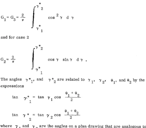
3 a r e called illumination integrals.The factor, G, allows for the finite length of the window just a s the factor obtained from the auxiliary protractor does in the BRS method for daylight factor calculation. In fact, the BRS protractor No. 2 gives the Gfactor for c a s e s 1 and 3. They a r e :
*
"direct1' means that interreflections within the room a r e not taken into account.and f o r c a s e 2
' 1
The angles y and y
*
a r e related to y2 Y 2 y
el,
and Q2 by the expressionsel
+ 8 tan y.* = tan y 21 1 COS
-
2tan y
*
= tan y + @22 2 COS
-
2where y and 7 a r e the angles on a plan drawing that a r e analogous to 2
i3 I and
e
2 on a vertidal section d r a 4 n g .-
Since the limits on the G integral a r e functions of 8, this function should really be evaluated for a l l values of 8 between 8 and 8 and then be in-
1 2
cluded with the other functions of 8 when evaluating the F functions. For most purposes, however, this complication i s not justified and it i s suffi-
cient to use the mean values 7 and 7 *2 given by the expression above.
T h e r e i s another small e r r o r inherent i n these Gfunctions. T h e r e i s no allow- ance for the fact that the radiationreflected from the glass has not quite the same angular distribution in the y- plane a s the direct radiation from the blind slat. But h e r e too the e r r o r i s so small that it does not justify fur- ther complicating the calculation of illumination factors.
11.7 Results
This paper has presented data f o r only one blind arrangement. The results given a r e for a standard light-coloured blind behind a sheet of ordinary window glass. (W/S = 1.2, absorptivity of slat = 0.4, absorption parameter,
k j
,
of glass = 0.1, slat angle = 45 degrees.)Figure 11.2 shows the blind luminance factors f o r illumination from a sky of uniform luminance, uniformly bright ground surface, and direct s o l a r irradiation at vertical shadow angles of 10,33 and 60 degrees. The 33-degree shadow angle i s the condition for maximum insolation on a vertical window; the 10-degree c a s e is the minimum shadow angle for no direct solar trans- mission through the blind, and 60 degrees i s representative of the midday shadow angle that occurs for south windows in summer.
The following example illustrates the use of these data.
Problem : Find the maximum luminance of a standard venetian blind a s seen by the occupants of a room with a western exposure.
Data : Maximum insolation occurs a t y/ = 330
Direct solar insolation = 75 watts/ft 2 = 6750 lumens/ft Sky luminance = 800 ft-lamberts Ground luminance ( p = 0.2 ) = 1000 ft-lamberts Transmittance of g l a s s = 0.82 for direct beam
Paper 11
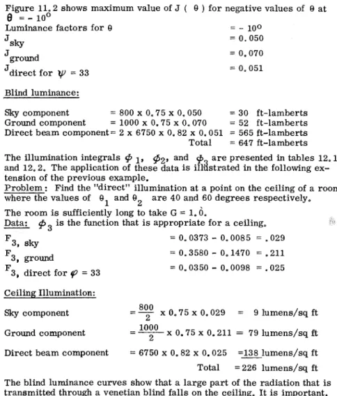
Figure 11.2 shows maximum value of J ( 8 ) f o r negative values of I3 a t
e
=-
100Luminance factors for 8 = - 100 J
sky = 0.050
Jground = 0.070
Jdirect f o r
W
= 33 = 0.051 Blind luminance:Sky component = 800 x 0.75 x 0.050 = 30 ft-lamberts Ground component = 1000 x 0.75 x 0.070 = 52 ft-lamberts Direct beam component= 2 x 6750 x 0.82 x 0.051 = 565 ft-lamberts Total = 647 ft-lamberts The illumination integrals @ 1,
g2,
and9
a r e presented in tables 12.1 and 12.2. The application of these data is ildstrated in the following ex- tension of the previous example.Problem: Find the "direct1' illumination at a point on the ceiling of a room where the values of O1 and O2 a r e 40 and 60 degrees respectively.
- -
The room is sufficiently long to take G = 1.0.
Data:
p3
is the function that is appropriate f o r a ceiling.-
F 3, sky = 0.0373-
0.0085 = -029 F3, ground = 0.3580-
0.1470 = -211 F3, direct for y? = 33 = 0.0350-
0.0098 = .025 Ceiling Illumination:Sky component --
-
By
x 0.75 x 0.029 = 9 lumens/sq ft Ground component--
-1°iO
x 0.75 x 0.211 = 79 lumens/sq ftDirect beam component = 6750 x 0.82 x 0.025 = ~ l u m e n s / s q ft Total = 226 lumens/sq ft The blind luminance curves show that a large part of the radiation that is transmitted through a venetian blind falls on the ceiling. I t is important, therefore, to have a light-coloured ceiling so that a s much a s possible of this light will be reflected downward a s useful illumination. These results also suggest that there should be some provision for heat extraction from the ceiling since even a light-coloured surface absorbs about half of the so- l a r radiation falling on it.
11.8 Conclusion
Venetian blinds a r e a useful type of window shade because they can inter- cept the direct rays of the sun and still allow a partial view through the window. They have a sufficiently low luminance when viewed from the nor- mal position of the occupants that they do not cause glare; but, at the same time, they transmit enough daylight toward the ceiling to provide a reason- able standard of illumination throughout the room.
The computations that have been m d e during this study have provided data that a r e needed f o r calculating blind luminance and the luminance of sur- faces in a room with venetian blinds. The computations have included the reflection by the window pane and the variation of luminance over the width of the blind slats. I t has been assumed that the slats a r e flat and that they reflect diffusely.
There has been no experimental confirmation of the results.
11.9 Acknowledgements
computation of the r e s u l t s . T h e progi-amming of the blind luminance cal- culations was done by Miss J. Proudman and M i s s G. E. Shaver of the No R. C. Computation Centre. T h e p r o g r a m to evaluate the illumination integrals was p r e p a r e d by Mr. Gilles Arseneault of the Division of Buil- ding Research.
T h i s p a p e r i s a contribution f r o m the Division of Building R e s e a r c h of the National R e s e a r c h Council, Canada and i s published with the p e r m i s s i o n of the D i r e c t o r of the Division.
R E F E R E N C E S
1 P a r m e l e e , G. V., and Aubele, W. W., The shading of sunlit g l a s s
-
an analysis of the effect of uniformly spaced flat opaque s l a t s , T r a n s . ASHVE, Vol. 58, 1952, p. 377.2 P a r m e l e e , G. V., Aubele, W. W. and Vild, D. J . , T h e shading of sunlit g l a s s
-
an experimental study of slat-type sun s h a d e s , T r a n s . ASHVE, Vol. 59, 1953, p. 221.3 P a r m e l e e , G. V. and Vild, D. J.
,
Design data f o r slat-type sun s h a d e s f o r u s e in load estimating, T r a n s . ASHVE, Vol. 59, 1953, p. 403.4 Moon, P. and Spencer, D. E . , Optical transmittance of louver s y s t e m s , J o u r n a l of the Franklin Institute, Vol. 273, No. 1, J a n u a r y 1962, p. 1.
5 O I B r i e n , P. F., Luminous flux t r a n s f e r in louvers, Illuminating Engi- neering, Vol. 58, No. 5, May 1963, p. 346.
6 Nicol, J. F . , Radiation transmittance c h a r a c t e r i s t i c s of louver s y s t e m s , Building Science, 1 , (3), 1966, 167
-
182.Fig. 11.1
Paper 11
Fig, 11.2
Fig. l l , 3 Vertical section
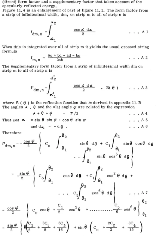
Fig. 11.4
Enlarged view of c r o s s section through window and blind
l
mage
Fig. 11.5
Angular co-ordinates f o r light ray incident on
Glass
window glass
Paper 11
Table 11.1 Illumination i n t e p a l s for the sky-diffuse and ground
-
reflected solar radiation8
90 80 7 0 60 50 4 0 3 0 20 10 0 -10 -20 -30 -40 -50 -60 -70 -80 -90Table 11.2 Illumination integrals for the direct beam
Sky $1 $2 @3 .0705 -1450 -1123 .0690 -1265 .0980 .0620 .lo25 .0710 .0450 .0615 .0373 -0307 .0355 .0150 ,0245 .0263 .0085 .0190 .0197 .0050 .0135 .0137 .0025 .0070 -0072 .0005
.
0000.oooo
.oooo
-.0207 -00208 -00011 -.0297 -.0305-.
0033 m.0363 -00377 -00066 -.0417 -.0440 -.0103-.
0455 -00493-.
0140 -.0482 -00540 -00180-.
0500 -.0578 -.0213 -.0510 -.0612 -00246 -.0512-.
0645 -.0277v
8
90 80 Ground $1s!
2 $3 -5260 .7143 -3820 .5243 ,6953 .3800 -5211 .6763 .3790 .5053 .6433 .3580 .4363 .5233 .2600 .3233 -3583 .I470 .2133 .2273 .0680 .I223 .I233 .0240 .0483 .0483 .0040.oooo
.oooo
.oooo
-.0100 -.0100 -.0015 -.0220 -.0230
-.
0040 -00330 -.0340 -.0080 -.0400 -.0430-.
0140 -00450 -.0510 -.0190 -00495-.
0580 -.0250 -.0520 -.0650 -.0310 -.0535-.
0700 -.0370 -.0540-.
0760 -.0430 10@
1 $2 $3 .0845 .2107 .I670 .0781 .I550 .I210 33 $1!#
2 453 .0700 .I395 .lo23 .0697 .I290 .lo07 60 $1 $2 $3 .0600 .lo05 -0790 .0593 .lo02 .0768Appendix 11. A
F o r m factor between a s t r i p on a s l a t and the image of another s t r i p
The f o r m factor f f o r radiant energy exchange between any two a r e a s . m, n
Am and An, i s the ratio of the radiation emanating f r o m A that falls on m
An, to the total radiation emanating f r o m A m ' When energy i s t r a n s f e r r e d between the two s u r f a c e s due to specular reflection a t some third s u r f a c e i t i s convenient to include the specularly reflected energy with the d i r e c t radiant interchange. In this c a s e the f o r m factor i s the s u m of the ordinary (direct) f o r m factor and a supplementary factor that takes account of the specularly reflected energy.
Figure 11.4 i s an enlargement of p a r t of figure 11.1. The f o r m factor from a s t r i p of infinitesimal width, dm, on s t r i p m to all of s t r i p n i s
cos d d~ 2
When this i s integrated over a l l of s t r i p m it yields the usual c r o s s e d string formula
The supplementary f o r m factor f r o m a s t r i p of infinitesimal width d m on s t r i p m to a l l of s t r i p n i s
d'2
where R (
0
) i s the reflection function that is derived in appendix 11. B The angles d,
8
and the s l a t angle (D a r e related by the expressiond + Q + $ O = T / 2
.
.
. A 4Thus c o s = sin
6
sin (P+
cos6
sin (P. .
. A 5 Therefore i s i n 6 d o + C, sin r 6.
c o s8
2 c o s d d+
Paper 11 5C 5 3C3
+
--)
+
sin0
cos2B
(+-
+ - + s i n e cos0
(2
+-
8 1 6 1 5 5C5)
+
sin 0 cos4e
(3)
The inclusion of the R (
0
) function so complicates the expression for f'dmy n that it is impractical to try to integrate it over strip m in the usual way. It i s much more convenient to evaluate f 1 at several points acrossdm, n strip m and then integrate numerically to get f1 m y n'
Appendix 11. B
Radiation from a blind that i s reflected by the window pane
Much of the radiation that falls on a venetian blind is reflected back toward the window pane. When this reflected radiation s t r i k e s the surface of the glass partof i t i s again reflected, and this reflection by the windowglass is specular. The reflectivity of glass depends on the angle of incidence of the light r a y s o the luminance of the image of a blind slat depends on the direction from which it is viewed.
Figure 11.5 shows a light r a y incident on the YZ plane from the direction (
,
7 ) where6
and7
a r e angular co-ordinates of the ray direction measured on orthogonal planes. If the YZ plane is taken a s the plane of the window glass and P a s a point on the surface of a blind slat, the flux densi- ty incident a t point 0 on the glass isFlux density = cos i dw
Where L i s the luminance of the slat a t point P in the direction toward 0.
The reflected flux density i s
Reflected flux density =
/j"ltt~~~
1P
($ dwwhere (i) is the reflectivity of the glass a t 0 f o r radiation incident on i t a t an angle i.
Thus the mean reflectivity of the surface a t 0 is
Jlat
i
c o s ip(i)
dw-
P =
flslat
L cos i dwJJ
The reflectivity of a glass surface can b e expressed a s
p
(i) =C
r. c o s ]i. 1The coefficients r . , f o r different types of c l e a r glass a r e given in appendix
11. C. 1
cos i = cos
0
.
COST~ h u s if the blind slat luminance is independent of the Z co-ordinate and the s l a t g o e s f r o m z = - m t o Z = + w ( i . e . = - 7 7 / 2 t o 7
= +
V/2), the glass reflectivity can be expressed a s a function of5 -7 L j=o r . cos c o s j+2
7
dy
R ( 0 ) = I -77/2r
n/2 0 cos 0/
c o s L y dy
j =C
C cos9
j=o jAppendix 11. C
Reflection, absorption and transmission coefficients for a single sheet of glass
The reflectance, absorptance and transmittance of a single sheet of glass depend on the thickness and type of glass, and on the angle at which the radiation strikes the surface. The parameters a r e :
K~
the product of extinction coefficient of the glass and the thickness of the sheet;i the angle between the incident ray and the normal to the surface;
"7
the index of refraction of the glass.The reflectance, absorptance and transmittance have been evaluated by Fresnel's relationships f o r many combinations of K and i for glass with
1
refractive index of 1.52. The results of these calculations have been ap- proximated by polynomial expressions using cos i a s the argument : i, e . ,
5
j reflectance, p (i) = =: r. cos i
J 5 j absorptance, (i) = =: a. c o s i J 5 transmittance,
7
(i) =f=
t . c o s 'i J Since p + d + 7 = 1, it follows that ro + a. + to = 1 and r.+
a . + t = 0 for j>
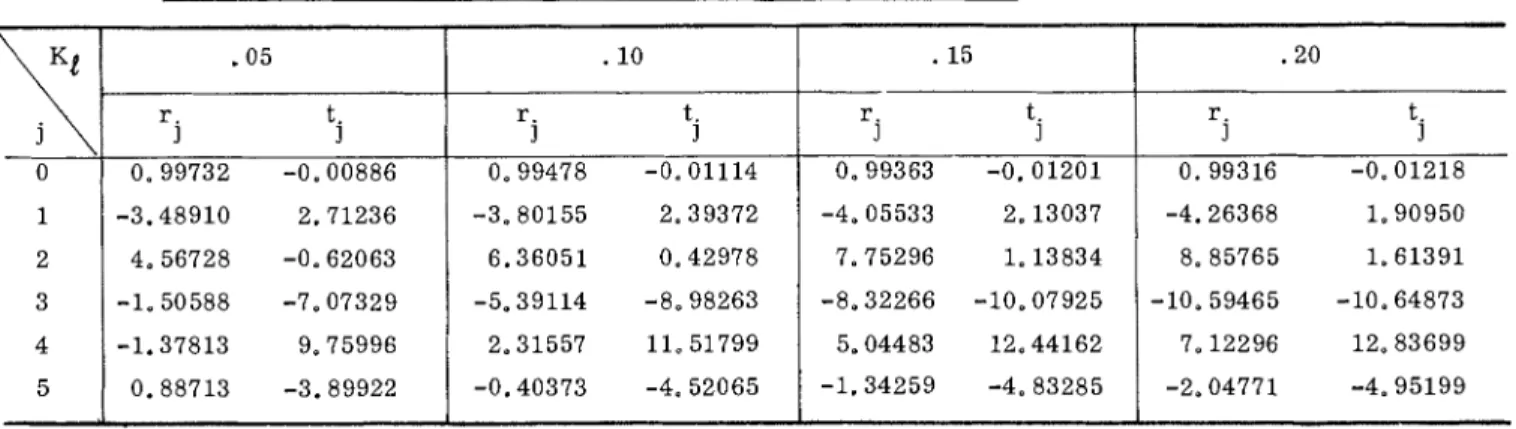
0 J J ~Table 11.3 gives the values of r . and t. for the range of K that includes
J J 1
ordinary window glass and c l e a r plate glass. If the a . coefficients a r e J
required they can be evaluated from the values of r . and t.. J J Table 11.3 Reflection and transmission coefficients for c l e a r window glasses