SCIENTIFIC ARTICLE
Three-dimensional hindfoot alignment measurements based
on biplanar radiographs: comparison with standard
radiographic measurements
Reto Sutter&Christian W. A. Pfirrmann&
Norman Espinosa&Florian M. Buck
Received: 20 July 2012 / Revised: 11 October 2012 / Accepted: 29 October 2012 / Published online: 20 November 2012 # ISS 2012
Abstract
Objective To establish a hindfoot alignment measurement technique based on low-dose biplanar radiographs and com-pare with hindfoot alignment measurements on long axial view radiographs, which is the current reference standard. Materials and methods Long axial view radiographs and low-dose biplanar radiographs of a phantom consisting of a human foot skeleton embedded in acrylic glass (phantom A) and a plastic model of a human foot in three different hindfoot positions (phantoms B1–B3) were imaged in dif-ferent foot positions (20° internal to 20° external rotation). Two independent readers measured hindfoot alignment on long axial view radiographs and performed 3D hindfoot alignment measurements based on biplanar radiographs on two different occasions. Time for three-dimensional (3D) measurements was determined. Intraclass correlation coef-ficients (ICC) were calculated.
Results Hindfoot alignment measurements on long axial view radiographs were characterized by a large positional variation, with a range of 14°/13° valgus to 22°/27° varus (reader 1/2 for phantom A), whereas the range of 3D hindfoot alignment measurements was 7.3°/6.0° to 9.0°/10.5° varus (reader 1/2 for phantom A), with a mean and standard deviation of 8.1°± 0.6/8.7°±1.4 respectively. Interobserver agreement was high
(ICC=0.926 for phantom A, and ICC=0.886 for phantoms B1–B3), and agreement between different readouts was high (ICC=0.895–0.995 for reader 1, and ICC=0.987–0.994 for reader 2) for 3D measurements. Mean duration of 3D meas-urements was 84±15/113±15 s for reader 1/2.
Conclusion Three-dimensional hindfoot alignment measure-ments based on biplanar radiographs were independent of foot positioning during image acquisition and reader independent. In this phantom study, the 3D measurements were substantial-ly more precise than the standard radiographic measurements.
Keywords Ankle . Hindfoot . Alignment . Biplanar radiographs . Long axial view
Introduction
Congenital and acquired abnormalities of the foot and ankle are often associated with a varus or valgus misalignment of the hindfoot [1–3]. Hindfoot alignment is first estimated clinically during the physical examination, and is subse-quently quantified on radiographs as a basis for treatment decisions, preoperative planning, and monitoring of the postoperative course [4–10]. The measurement of hindfoot alignment has been described on hindfoot alignment view radiographs (also called the Cobey view) and long axial view radiographs [4]. Measurements on long axial view radiographs are characterized by a superior inter-reader agreement, compared with Cobey view radiographs [11]. However, all hindfoot alignment measurements based on standard radiographs have a considerable interobserver var-iability and even moderate malpositioning can lead to sub-stantial measurement errors [11,12].
Recently, low-dose simultaneous biplanar X-ray scanners were introduced [13, 14]. Biplanar radiographs can be
R. Sutter (*)
:
C. W. A. Pfirrmann:
F. M. Buck Department of Radiology, University Hospital Balgrist, Forchstrasse 340,8008 Zurich, Switzerland e-mail: Reto.Sutter@balgrist.ch N. Espinosa
Department of Orthopedic Surgery, University Hospital Balgrist, 8008 Zurich, Switzerland
R. Sutter
:
C. W. A. Pfirrmann:
N. Espinosa:
F. M. Buck University of Zurich, 8006 Zurich, Switzerlandutilized for measuring anatomical axes and angles in the three-dimensional (3D) space with a good reliability in a weight-bearing position [13,15]. To pursue a reliable mea-surement technique that is less prone to meamea-surement errors due to rotational misplacement at the time of image acqui-sition, we developed a technique for measuring hindfoot alignment based on biplanar radiographs with 3D reprojec-tion. The biplanar radiographic scanner has the substantial advantage over traditional radiographs of simultaneous ac-quisition in two planes, which allows a 3D model to be generated on the scanner software based on the anatomical information of the two planar views [13,15]. When an angle is measured in this 3D model with the use of anatomical landmarks, measurement errors that are often seen on stan-dard radiographic assessment of the hindfoot alignment can be reduced.
The purpose of our study was to establish a hindfoot alignment measurement technique based on low-dose bipla-nar radiographs and to compare this technique with hindfoot alignment measurements on long axial view radiographs.
Materials and methods
No institutional review board approval was needed for this phantom study. Two different types of phantoms were used for this study: phantom A consisted of a human right foot and distal lower leg skeleton embedded in an anatomically-shaped acrylic glass, and phantom B consisted of a plastic model of a human left foot and lower leg. The hindfoot configuration was fixed in a single position for phantom A. In phantom B, three different hindfoot positions (phantom B1, B2, and B3) were assembled, whereas the calcaneus was fixed to the cuboid and the talus with instant glue in three different positions (hindfoot alignment in varus, neu-tral, and valgus positions).
Measurements on long axial view radiographs
Long axial view radiographic measurements served as the reference standard. The radiographs were obtained with a fully digital radiography system (Ysio; Siemens Healthcare, Erlangen, Germany) in a standardized fashion [11]. The images were acquired with a distance between the X-ray tube and the detector plate of 1.5 m, and with a 50-kV tube voltage and a 4.1-mAs tube load. The foot was placed on top of the detector plate, with the X-ray beam tilted 45° cranio-caudally [8,11]. For the long axial view radiographs in the neutral position the medial contour of the foot was posi-tioned parallel to the X-ray beam. The radiographs were acquired nine times at different degrees of rotational mis-placement (range: 20° internal rotation to 20° external rota-tion) in each phantom.
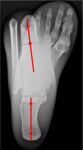
Hindfoot alignment was quantified on the radiographs by measuring the angle between the tibial shaft axis and the calcaneal axis (Fig.1) [12]. The tibial shaft axis was defined by the line connecting the midpoints of two pairs of points on the cortex of the distal tibia. A minimum distance of 3 cm was maintained between these two pairs of points. The calcaneal axis was defined as the line connecting the midpoint between the lateral edge of the calcaneus at the level of the subtalar joint and the corner at the inferior aspect of the sustentaculum base, and the midpoint between the medial and lateral contour of the posterior calcaneal process (Fig.1).
Measurements on biplanar radiographs
Immediately after acquiring the radiographs all phantoms were examined in a low-dose simultaneous biplanar X-ray scanner (EOS imaging system; EOS Imaging Inc., Paris, France), that features a C-arm with linear movement, where two separate imaging systems that are located perpendicular
Fig. 1 Long axial view radiograph (LAR) of human foot skeleton embedded in acrylic glass (phantom A). The hindfoot alignment was measured between the tibial shaft axis and the calcaneal axis (unbroken red lines). These axes are defined by connecting the midpoints (points) of two accessory lines (dotted lines). The radiograph was acquired with the phantom positioned at 15° internal rotation
to each other simultaneously acquire one image each. An anteroposterior image (tube voltage, 85 kV; tube current, 160 mA) and a lateral image (tube voltage, 80 kV; tube current, 100 mA) were acquired simultaneously with an acquisition duration of 1.9 s (Fig.2). Biplanar radiographs were acquired nine times in each phantom at different degrees of rotational misplacement (range: 20° internal to 20° external rotation). The positioning of the phantoms was performed manually with the help of the scanner’s reference laser and a standard medical goniometer.
The biplanar radiographic data were subsequently pro-cessed using the manufacturer-specific software (sterEOS software, EOS imaging system; EOS Imaging, Paris, France). This software allows for unequivocal identification of a point in the 3D space defined by its projection on the two perpendicular biplanar images (anteroposterior and lateral images, which were acquired in one simultaneous acquisi-tion) and the use of anatomical landmarks. Hindfoot align-ment was measured based on the specific anatomical landmarks listed below. These landmarks were placed sepa-rately by two independent readers in the sterEOS software, with the use of the“3D toolbox,” which can identify lines and points in a 3D coordinate system based on their position on two perpendicular planar views. Based on these landmarks a custom-built Matlab code calculated the hindfoot alignment angle in a similar fashion to the so-called“simplified person-alized parametric model” that is implemented in the sterEOS software for other anatomical regions (Fig.3) [15].
First, the tibial shaft axis was defined by the line con-necting the midpoints of two pairs of points on the cortex of the distal tibia (Fig.2). Analogous to the long axial view radiographic measurements, a minimum distance of 3 cm was maintained between these two pairs of points, and both points were placed at least 4 cm proximal to the ankle in order to obtain reliable measurements.
Second, the hindfoot axis was defined by the line con-necting a proximal and a distal reference point (Fig.2). The proximal reference point was set on the cortex of the talus at the highest point of the trochlea on the lateral image, and at the midpoint of the trochlea on the anteroposterior image. The distal reference point was set on the cortex of the calcaneus at the lowest point of the calcaneus on the lateral image, and at the midpoint between the medial and lateral plantar tubercle of the calcaneus on the anteroposterior image (Fig.2).
Third, a sagittal reference line of the foot was drawn along the medial contour of the foot. This line was defined by a reference point on the calcaneus and a second reference point on the head of the first metatarsal bone (Fig.2). On the calcaneus, the point was placed on the medial process of the calcaneus on the lateral image, and on the medial edge of the calcaneus on the anteroposterior image. The reference point at the head of the first metatarsal bone was positioned on the medial contour of the head on the anteroposterior image, and in the center of the head on the lateral image. The time needed to manually define all reference points was deter-mined for each reader.
The biplanar radiographs and annotated reference lines and points were saved in the DICOM (digital imaging and com-munications in medicine) format and then analyzed using a custom-made Matlab code (Mathworks, Natick, MA, USA), which automatically calculates the hindfoot alignment, using a 3D reprojection (Fig.3). This Matlab code calculated the 3D hindfoot alignment by using the tibial shaft axis, the hindfoot axis, and the sagittal plane (as defined in our model by the axis of the tibia and the sagittal reference line of the foot), based on the reference lines and points that were saved in the DICOM data of each examination. Positive values indicated a hindfoot varus alignment, and negative values indicated a hindfoot valgus alignment.
Fig. 2 Biplanar radiographs of phantom A in the a anteroposterior view and b the lateral view. Reference points are positioned simulta-neously on both images on the scanner software to define the tibial shaft axis (vertical red line), the hindfoot axis (oblique red line), and the sagittal reference line (white line). Accessory lines (dotted lines) are
used for the correct positioning of the measurement lines (these are positioned at the red midpoints of the accessory lines). The three dimensional hindfoot alignment is then calculated using a custom-made Matlab code. The images shown were acquired with the phantom positioned at 15° external rotation
Statistical analysis
Descriptive statistics were used to characterize the hindfoot alignment, and the mean values and standard deviations were calculated. Interobserver agreement and agreement between the first and second measurement were calculated using the intraclass correlation coefficients (ICC). All anal-yses were performed using statistical software (SPSS for Windows, release 17.0; SPSS, Chicago, IL, USA).
Results
Measurements on long axial view radiographs
Long axial view radiographic measurements showed a large variation in hindfoot alignment measurements for the dif-ferent rotational positions for all phantoms. The range of measurements for phantom A on the long axial view radio-graphs was−14° (valgus) to 22° (varus) for reader 1, and −13° (valgus) to 27° (varus) for reader 2 (Figs.1and4). For phantom B1 the range of measurements on the long axial view radiographs was −14° (valgus) to 22° (varus) for reader 1,−13° (valgus) to 24° (varus) for reader 2, and the range of measurements on the long axial view radiographs was similar for phantoms B2 and B3 (Fig.5).
Measurements on biplanar radiographs
Three-dimensional hindfoot alignment measurements based on biplanar radiographs showed an increased measurement stability for different rotational positions compared with the
long axial view radiographs, both for phantom A (Figs. 3
and4) and for phantoms B1, B2, and B3 (Fig.5).
The 3D hindfoot alignment measurements for phantom A ranged from 7.3° to 9.0° (varus) for reader 1, and from 6.0° to 10.5° (varus) for reader 2, with a mean angle of 8.1°±0.6 for reader 1, and 8.7°±1.4 for reader 2 for the first readout (Fig. 4). The measurements obtained at the second readout for phantom A were similar to the first readout, ranging from 7.0° to 9.5° (varus) for reader 1, and from 8.0° to 9.6° (varus) for reader 2, with a mean angle of 7.9°±0.8 for reader 1, and 8.9°±0.5 for reader 2. Inter-reader agreement was high for measurements with phantom A (ICC=0.926), and also agreement between different readouts was high (ICC=0.995 for reader 1, and ICC=0.994 for reader 2).
Fig. 3 Schematic illustration of the three dimensional (3D)-hindfoot alignment measure-ment method that was used for the biplanar radiographic data. The hindfoot angle is defined by the tibial shaft axis and the hindfoot axis (red lines). Using the reference points described in Fig.2the Matlab code measures the misalignment (β) of the medial contour of the foot (white line) versus the sagittal plane and subsequently obtains the projected tibial shaft axis and hindfoot axis (blue lines) on the coronal plane via a 3D reprojection. The hindfoot alignment (α) is then measured automatically on the coronal plane. A photograph of phan-tom A is depicted to illustrate measurements
Fig. 4 Hindfoot alignment in phantom A, as measured by reader 1 (black) and reader 2 (gray) on biplanar radiographs with three-dimensional measurements (unbroken line), compared with standard long axial view radiographs (LAR; dashed line). The phantom was placed in different positions from 20° (internal rotation) to−20° (external rotation). Negative hindfoot alignment values indicate a valgus hindfoot alignment and positive values indicate a varus hindfoot alignment. Data from the first readout are displayed
The 3D hindfoot alignment measurements for phantom B1 ranged from 2.8° to 6.4° (varus) for reader 1, and from 1.0° to 4.4° (varus) for reader 2, with a mean angle of 4.2°± 1.1 for reader 1, and 3.0°±1.3 for reader 2 for the first readout (Fig.5). The measurements obtained at the second readout for phantom B1 were similar to the first readout, ranging from 3.5° to 8.5° (varus) for reader 1, and from 0.8° to 4.8° (varus) for reader 2, with a mean angle of 6.7°±1.7 for reader 1, and 3.1°±1.3 for reader 2.
The range and mean values of the 3D hindfoot alignment measurements were similar for phantoms B2 and B3 (Fig.5). Inter-reader agreement was high for measurements with phantoms B1, B2, and B3 (ICC=0.886), and agree-ment between different readouts was also high (ICC=0.895 for reader 1, and ICC=0.987 for reader 2).
Mean duration of 3D hindfoot alignment measurements based on the biplanar radiographs was 84±15 s (range, 60– 126 s) for reader 1 and 113±15 s (range, 92–153 s) for reader 2.
Discussion
The clinical assessment of hindfoot alignment and its radio-graphic quantification have gained considerable importance in the last few years, both for the initial assessment and for the postoperative monitoring of patients with various abnormali-ties of the foot and ankle [7,8,10,11]. A precise assessment of the hindfoot alignment is crucial in patients who undergo an ankle arthrodesis to plan the re-alignment of the hindfoot and to reproduce a physiological gait pattern, or in patients with acquired flatfoot deformity where a tendon repair or tendon transfer is supplemented by a medial displacement calcaneal osteotomy [9,10,16]. However, so far, no method is available that allows a precise measurement of hindfoot alignment in daily radiological practice [11,12].
Incorrect positioning of the foot can lead to substantial measurement errors when assessing the hindfoot alignment on radiographs, which is the current reference standard [12]. In patients with foot deformities, the exact positioning can be quite difficult for the radiology technician, and a mea-surement stability of ± 5° has been considered acceptable for these radiographs [12, 17]. A hindfoot angle of about 5° valgus is considered a normal hindfoot axis, and both valgus angles over 10° or any hindfoot varus angle are considered abnormal [12,17]. With measurement stability of ± 5° for different rotational positions and considerable inter-reader variability for standard radiographic measurements, howev-er, there is no clear boundary between normal and abnormal hindfoot angles [12].
The most reliable standard radiographic hindfoot align-ment measurealign-ments are currently achieved by long axial view radiographs, a technique that is superior to the previously-used Cobey view radiographs [11, 12]. To the best of our knowledge, our study introduces, for the first time, hindfoot alignment measurements based on biplanar radiographs, with a method that is not dependent on the manufacturer. We were able to show that 3D hindfoot align-ment measurealign-ments based on biplanar radiographs were substantially better than measuring the hindfoot alignment on the long axial view radiographs, thus making it easier to determine whether a hindfoot alignment is physiological or
Fig. 5 Hindfoot alignment in phantom B1 (top; varus hindfoot align-ment), B2 (middle; valgus hindfoot alignalign-ment), and B3 (bottom; neu-tral hindfoot alignment), as measured by reader 1 (black) and reader 2 (gray) on biplanar radiographs with three-dimensional measurements (unbroken line), compared with standard long axial view radiographs (LAR; dashed line). The phantoms were placed in different positions from 20° (internal rotation) to−20° (external rotation). Negative hindfoot alignment values indicate a valgus hindfoot alignment and positive values indicate a varus hindfoot alignment. Data from the first readout are displayed
whether it is abnormal. As a correct assessment of the hind-foot alignment is an important element in the treatment of various hindfoot or ankle abnormalities, 3D hindfoot align-ment measurealign-ments could improve both the initial evalua-tion and planning of therapy in patients with condievalua-tions such as acquired flatfoot deformity or in patients who undergo ankle arthrodesis, as well as for the assessment of the post-operative course in such patients [9,10,16]. Hindfoot align-ment can be assessed with the biplanar X-ray scanner in an upright weight-bearing position, which might be helpful for the quantification of hindfoot alignment when a decision needs to be made on whether the hindfoot alignment is physiological or abnormal, and whether or not to perform a calcaneus osteotomy in a patient. Furthermore, the hindfoot alignment can be calculated using the method described in our study based on low-dose biplanar radiographic data acquired in patients who undergo this examination for the quantification of leg length and the mechanical axis of the legs, which might allow additional radiographs for quantify-ing the hindfoot alignment to be omitted [18].
Contrary to the reference standard radiographs, the 3D hindfoot alignment measurements based on the biplanar radio-graphs are not dependent on the correct positioning of the foot at the time of image acquisition. This is advantageous com-pared with the reference standard radiographs used currently, where even minor malpositioning can lead to substantial measurement errors [11,12].
In conclusion, 3D hindfoot alignment measurements based on biplanar radiographs were independent of foot-positioning during image acquisition and reader-independent. The 3D measurements were substantially more precise than the long axial view radiographic measurements.
References
1. Van Bergeyk AB, Younger A, Carson B. CT analysis of hindfoot alignment in chronic lateral ankle instability. Foot Ankle Int. 2002;23:37–42.
2. Hayashi K, Tanaka Y, Kumai T, Sugimoto K, Takakura Y. Correlation of compensatory alignment of the subtalar joint to
the progression of primary osteoarthritis of the ankle. Foot Ankle Int. 2008;29:400–6.
3. Rammelt S, Amlang M, Barthel S, Gavlik JM, Zwipp H. Percutaneous treatment of less severe intraarticular calcaneal frac-tures. Clin Orthop Relat Res. 2010;468:983–90.
4. Cobey JC. Posterior roentgenogram of the foot. Clin Orthop Relat Res. 1976;202–7.
5. Weissman S. Standard radiographic techniques for the foot and ankle. Clin Podiatr Med Surg. 1988;5:767–75.
6. Saltzman CL, El-Khoury GY. The hindfoot alignment view. Foot Ankle Int. 1995;16:572–6.
7. Johnson JE, Lamdan R, Granberry WF, Harris GF, Carrera GF. Hindfoot coronal alignment: a modified radiographic method. Foot Ankle Int. 1999;20:818–25.
8. Lamm BM, Mendicino RW, Catanzariti AR, Hillstrom HJ. Static rearfoot alignment: a comparison of clinical and radiographic measures. J Am Podiatr Med Assoc. 2005;95:26–33.
9. Zwipp H, Rammelt S, Endres T, Heineck J. High union rates and function scores at midterm followup with ankle arthrodesis using a four screw technique. Clin Orthop Relat Res. 2010;468:958–68. 10. Frigg A, Nigg B, Davis E, Pederson B, Valderrabano V. Does
alignment in the hindfoot radiograph influence dynamic foot-floor pressures in ankle and tibiotalocalcaneal fusion? Clin Orthop Relat Res. 2010;468:3362–70.
11. Reilingh ML, Beimers L, Tuijthof GJ, Stufkens SA, Maas M, van Dijk CN. Measuring hindfoot alignment radiographically: the long axial view is more reliable than the hindfoot alignment view. Skeletal Radiol. 2010;39:1103–8.
12. Buck FM, Hoffmann A, Mamisch-Saupe N, Espinosa N, Resnick D, Hodler J. Hindfoot alignment measurements: rotation-stability of measurement techniques on hindfoot alignment view and long axial view radiographs. Am J Roentgenol. 2011;197:578–82. 13. Schlatterer B, Suedhoff I, Bonnet X, Catonne Y, Maestro M, Skalli
W. Skeletal landmarks for TKR implantations: evaluation of their accuracy using EOS imaging acquisition system. Orthop Traumatol Surg Res. 2009;95:2–11.
14. Deschenes S, Charron G, Beaudoin G. Diagnostic imaging of spinal deformities: reducing patients radiation dose with a new slot-scanning X-ray imager. Spine. 2010;35:989–94.
15. Chaibi Y, Cresson T, Aubert B et al. Fast 3D reconstruction of the lower limb using a parametric model and statistical inferences and clinical measurements calculation from biplanar X-rays. Comput Methods Biomech Biomed Engin. 2011;1.
16. Guha AR, Perera AM. Calcaneal osteotomy in the treatment of adult acquired flatfoot deformity. Foot Ankle Clin. 2012;17:247–58. 17. Coughlin MJ, Mann RA, Saltzman CL. Surgery of the foot and
ankle. 8th ed. Philadelphia: Mosby; 2007.
18. Dubousset J, Charpak G, Skalli W, Kalifa G, Lazennec JY. EOS stereo-radiography system: whole-body simultaneous anteroposte-rior and lateral radiographs with very low radiation dose. Orthop Reparatrice Appar Mot. 2007;93:141–3.