THE DESIGN OF A PANELIZED ROOF SYSTEM FOR
RESIDENTIAL CONSTRUCTION
by
Jordan Lewis Dentz
B.S.A.D., Massachusetts Institute of Technology 1988
SUBMITTED TO THE DEPARTMENT OF ARCHITECTURE
IN PARTIAL FULFILLMENT OF THE REQUIREMENTS FOR THE DEGREE OF
MASTER OF SCIENCE IN BUILDING TECHNOLOGY at the
MASSACHUSETTS INSTITUTE OF TECHNOLOGY June, 1991
© Massachusetts Institute of Technology 1991 All rights reserved
Signature of author...
(J
M Department of ArchitectureMay 10, 1991
Certified b
Leonard Morse-Fortier Assistant Professor of Building Technology
A ccepted by...
Leon K. Ulicksman Director, Building Technology Program
MASSACHUSErS 1NSTITUTE OF TECHNOLOGY
JUN
0 6 1991
THE DESIGN OF A PANELIZED ROOF SYSTEM FOR RESIDENTIAL CONSTRUCTION
by
Jordan Lewis Dentz
Submitted to the Department of Architecture on May 10, 1991 in partial fulfillment of the requirements for the degree of Master of Science in
Building Technology
Abstract
The cost of housing in the U.S. continues to rise faster than household income. Innovative building materials and construction technologies have the potential to reduce housing construction costs. One strategy to do this is componentization. There is a longstanding trend towards the increased use of components in U.S. residential
construction. One such type of component is the composite building panel, used for walls, roofs and floors. Presently the types of composite panels used in residential construction include pre-framed walls of standard construction and, more innovatively, structural foam-core panels with wood or wood composite faces.
This thesis focuses on the design of a panelized roofing system for residential construction. The roof was chosen for various reasons. It includes some of the most complicated geometrical and structural challenges. It is often the most difficult area of the house to frame conventionally. Its construction is a crucial step in getting the house weathertight. For these reasons and others builders have identified it as a prime target for innovation.
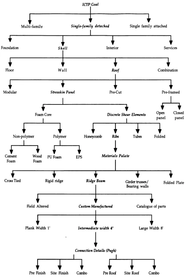
The design of the panelized roof system is illustrated as a tree of decisions. The path traveled down this tree led to a ribbed panel spanning from eave to ridge. A design
selection method developed by Stuart Pugh was used to design the connection details of the system. The interdisciplinary design process used to design the roof system is examined and evaluated in light of the results it yielded.
Mock-ups, models and a full scale proof-of-concept structure were built. These constructions were used as learning tools during design and to demonstrate and evaluate the performance of the roof system design.
Thesis Supervisor: Dr. Leonard Morse-Fortier Title: Assistant Professor of Building Technology
Acknowledgements
First, I would like to thank the people involved in the Innovative Housing Construction Technologies Program at MIT (IHCTP). This work would not have been possible without the cooperation of these faculty, researchers and students. I would especially like to express my gratitude to the people who participated in the, sometimes tedious, joint design process: Prof. Leonard Morse-Fortier, Prof. Carl Peterson, John
Crowley, Michel Parent and Mohammed Maleej. Also, thanks are due John Pflueger for introducing me to the Pugh process, and Mark Kucirka and Mike Toole for helping me understand the project's background.
I was fortunate to have three advisors, all of whom took a sincere interest and active role in my work. I would like to thank each of them: Prof. Leonard Morse-Fortier of the building technology program, for the great amount of time and effort he spent with me on the project, for his contageous enthusiasm and for his friendship; John Crowley, a Research Associate in Architecture for his knowledge and advice; Prof. Leon Glicksman, head of the building technology program, for his academic guidance and 'big picture' view of the project.
The very nature of this thesis being an integration of many specialties into the design of a complex system, means that many of the ideas and research contained herein originated with people other than the author. Where possible, credit has been given to those responsible, however, many of the concepts were collaberative efforts where no one person alone owns the idea. I would like to thank all those who shared their ideas, for they will recognize some form of them in here.
I appreciate the funds provided by the Innovative Housing Construction Technologies Consortium that made this work possible.
Finally, I want to thank the guys who helped me carry the 16', 250 lb panels up to the fourth floor: Ruel, Kris, Ben, Paul, Dave, Kevy, and Mohammed. I still owe some of you ice cream.
Table of contents
A bstract ... 3
Acknowledgements...4
Table of contents... 5
List of figures and tables...8
CHAPTER 1 Introduction ... 11
1.1 The rationale for technological innovation in housing ... 11
1.2 The Innovative Housing Construction Technologies Program ... 13
1.3 The role of this thesis ... 15
CHAPTER 2 Background ... 18
2.1 Review of conventional stick frame construction ... 18
2.2 Current technology in prefabricated residential construction in the U .S ... 2 1 2.2.1 HUD code mobile homes ... 21
2.2.2 Modular...23
2.2.3 Panelized...23
2.2.4 Pre-cut...23
2.3 Current residential panel technology ... 24
CHAPTER 3 Design goals of roof system...33
3.1 Architectural design capabilities ... 34
3.2 Aesthetic requirements -finishes: ... 35
3.3 Aesthetic requirements -details...36
3.4 The public's perception of prefabricated construction ... 36
3.5 Market position of panel system...38
3.6 Benefit to the decision maker ... 41
3.7 Manufacturing ... 42
3.8 Transportation ... 43
3.9 Erection... 45
3.10 Construction time ... 47
3.11 Compatibility with conventional construction ... 48
3.12 Code compliance...50
3.12.1 Fire performance...50
3.12.2 Structural performance...51
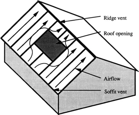
3.13 Preventing moisture and heat induced damage to the roof: ventilation
of the roof surface...52
3.14 Summary of design goals... 54
CHAPTER 4 Design decisions... 56
4.1 The decision tree... 56
4.1.1 What type of housing? -Single family detached...59
4.1.2 Why the building shell?... . . . . 59
4.1.3 Why roof panels?... . . . . 60
4.1.4 Stressed skin panels...62
4.1.5 Discrete shear elements in the core...63
4.1.6 Ribs...69
4.1.7 Materials ... 72
4.1.8 Structural options for the pitched roof... 76
4.1.9 Manufacturing...80
4.1.10 Panel width - 4 feet ... 82
4.1.11 Connection details ... 84
4.1.12 Finishes...85
CHAPTER 5 Joint design... 87
5.1 The Pugh design process... 87
5.1.1 Criteria list... 89
5.2 Tolerances...93
5.3 Example of a Pugh session - The eave...95
5.3.1 The eave joint... 95
5.3.2 Eave Pugh session #1...96
5.3.3 Eave Pugh session #2...100
5.3.4 The eave design...102
CHAPTER 6 The roof panel system...104
6.1 The proof-of-concept structure...104
6.2 The panel...104
6.3 Joints ... 112
6.3.1 The panel-to-panel joint...113
6.3.2 R idge joint...117
6.3.3 Valley and hip joint...124
CHAPTER 7 Implications of the System ... 127
7.1 Implications for architectural design ... 127
CHAPTER 8 Evaluations and conclusions ... 134
8.1 Evaluation of the design process ... 134
8.2 Evaluation of the roof system ... 137
8.3 C onclusion ... 138
APPENDIX A Additional design ideas...140
A .1 Additional features...140
A .1.1 Built-in gutters...140
A.1.2 Metal roofing in conjunction with roof panels ... 141
A.1.3 Dormer component... ... 142
A .2 A lternative designs...144
A.2.1 Triangle roof panel system...144
A.2.2 Roof panels parallel to ridge line ... 146
APPENDIX B Joint concept tables ... 148
B. 1 Panel-to-panel joint .. ... 148
B.2 Ridge joint .... ... ... 149
B .3 V alleyjoint... ... 151
APPENDIX C Eave matrix sheet ... ... 151
APPENDIX D Example of a panel shop drawing ... 154
APPENDIX E Roof panel ventilation analysis...155
List of figures and tables
Figure 2.1 Conventional platform framing ... 19
Figure 2.2 Common roof trusses...20
Table 2.1 Percent of total construction cost ... 20
Table 2.2 Approximate construction time and crew size for five methods of construction...22
Figure 2.3 U.S. market share of homebuilding systems 1987 ... 22
Figure 2.4 Cross-section of a sandwich panel...26
Figure 2.5 Analogy of structural foam-core panel with a steel I-beam...26
Figure 2.6 Foam-core panel joints currently in use ... 27
Table 2.2 Components in use today and the site method or trade they replaced...29
Figure 2.7 Componentization...30
Figure 3.1 Costs offour roof systems for simple and complex roofs ... 39
Figure 3.2 Residential roof cost for roof parts of increasing complexity ... 39
Figure 3.3 Common roof forms ... 40
Figure 3.4 Market position of competing roof systems...40
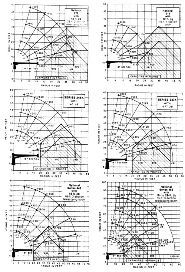
Figure 3.6 Hydraulic boom crane ... 45
Figure 3.5 Crane capacities ... 46
Figure 3.7 Ventilation in a conventional rafter-framed roof...53
Figure 3.8 Two-way venting ... 54
Figure 4.1 The decision Tree ... 57
Figure 4.2 Conventional roofframing ... 61
Figure 4.3 Roof panel configuration for Kucirka program... 64
Table 4.1 Kucirka Program input parameters...65
Table 4.2 Kucirka Program results ... 66
Table 4.3 Properties of candidate core and insulating materials ... 67
Table 4.4 Properties of candidate face materials...68
Table 4.5 Moduli and Insulating value per dollar per board-foot for Candidate M aterials ... ... 68
Figure 4.4 Panel core sections...71
Table 4.6 Thermal bridging cross sectional area of discreet shear element p anels ... . . ... 71
Table 4.7 Properties of insulation materials...75
Figure 4.5 Basic pitched roof structural strategies ... 75
Figure 4.7 Figure 5.1 Figure 5.2a Figure 5.2b Figure 5.2c Figure 5.2d Figure 5.2e Figure 5.2f Figure 5.3a Figure 5.3b Figure 5.3c Figure 5.4 Figure 6.1 Figure 6.2a Figure 6.2b Figure 6.2c Figure 6.2d Figure 6.3a Figure 6.3b Figure 6.4 Figure 6.5 Figure 6.6 Figure 6.7 Figure 6.8 Figure 6.9 Figure 6.10 Figure 6.11 Figure 6.12 Figure 6.13 Figure 6.14 Figure 7.1 Figure 7.2 Figure A.1 Figure A.2 Figure A.3 Figure A.4
NAHB components study ... 85
Birdsmouth cut ... 96 Sp ike ... 98 B irdsm outh ... 98 H ing e ... 99 F ram e ... 99 L edger ... 100 F la t-bo ttom ... 100 S crew ... 10 1 B irdsm outh ... 101 F ree-triangle ... 102
E ave deta il...103
P O C plan ... 105
Elevation of POC wall A ... 106
Elevation of POC wall B ... 106
Elevation of POC wall C ... 106
Elevation of POC wall D ... 107
Cross section of POC structure...107
Longitudinal section of POC structure...107
Panel cross section...108
Rib notching for 2-way ventilation...109
Shifting of panel neutral axis due to rib holes ... 110
Alternative rib-face connections ... 112
Structural requirements of the panel-to-panel joint...114
Tapered spline panel-to-panel joint...116
Ridge beams designed, developed, and tested at half scale ... 120
R idge detail ... 123
POC ridge beam loading ... 123
Valley detail...126
H ip detail... ... 126
Clustering of roof penetrations ... 129
Service distribution within the roof panel system ... 131
Gutter built into panel and conventional gutter ... 141
Seamed metal roofing on roof panels...142
Dormer component...143
Roof panels parallel to ridge line ... 146
Panel-to-panel joint concepts ... 148
Ridge joint concepts ... 149
Valley joint concepts ... 151
Eave matrix sheet ... 152
Panel shop drawing example ... 154
Hip ventilation diagram...157 Figure A.5 Figure B.1 Figure B.2 Figure B.3 Figure C.1 Figure D.1 Figure E.1
CHAPTER 1
Introduction1.1
The rationale for technological innovation in housingHousing costs have increased relative to household income over the past few decades. Homeownership rates are declining, especially among younger households. The high cost of buying a first house has forced many people to delay or give up the effort to become a homeowner [Harvard U., 89]. Part of this rise in housing costs is attributable to higher construction costs, and other costs influenced by construction factors; such as construction time. In 1982, the U.S. General Accounting Office reported that greater use of innovative building materials and construction techniques could reduce housing costs.
The technology of materials and manufacturing has advanced considerably in the past 20 years, but application of these advances to whole building systems for housing has lagged. The emergence of large, national builders enables larger investment to take place in the form of research, development and facilities. Also, there is an opportunity for use in the U.S. of technologies from Europe and Japan to apply to housing (similar to the way Japan borrowed the 2 x 4 building system from the U.S.). If this opportunity is ignored, it may become a threat of competition from large overseas builders who may work in
partnership with U.S. firms. This demands a greater commitment to applied building research in the U.S.
A number of demographic factors also influence the need for innovation in housing construction. It is predicted that the U.S. workforce will increase at the slowest rate since the 1930's. The construction industry traditionally depends on male workers, under 35 years of age, to replace retiring workers. This group is expected to decline by 3.5 million over the next ten years. These factors mean that homebuilders will face unprecedented
problems finding workers with construction trade skills in the future [NAHB, 91], [US DOL, 88].
Current house construction practice is problematic and becoming more so. Quality control of stick-frame houses is difficult, particularly with a decline in the availability of skilled workers. Stick-frame construction is inefficient in that it does not lend itself to economies of scale except on large tracts (California builders put the limit at 30 houses). As these large development tracts become fewer, smaller scattered site, or infill,
developments become the norm and the problem of inefficiencies becomes more important. Finally, rising costs of traditional materials for stick-frame construction will continue to drive up the cost of housing.
Many attempts have been made at lowering the cost of housing construction in the U.S. through technological innovation. The largest being the Department of Housing and Urban Development's Operation Breakthrough in the early 1970's. Unlike many of these technical efforts, the Innovative Housing Construction Technologies Program (IHCTP) at MIT is approaching the problem with a broader approach. Not only is the physical
building system being looked at, but also, the system in the context of the U.S. homebuilding industry's conservative, evolutionary nature. This approach examines industry structure, distribution channels, the service part of the homebuilding industry, the investment potential the industry posses, and most importantly, the market demands. Another important distinction, as discussed in section 3.4, is that the IHCTP is not
focussing exclusively on low cost housing, but rather on solutions that apply to all housing market segments based on their viability in the marketplace. As further explained below, the goal of the IHCTP is to identify and develop products to satisfy the next logical step in the continuing evolution of residential construction.
1.2
The Innovative Housing Construction Technologies ProgramThis thesis is based upon research completed with the Innovative Housing
Construction Technologies Program (IHCTP). The main goal of the IHCTP is to identify and propose innovative techniques to significantly improve both the quality and
affordability of newly constructed housing in the U.S. The objective is not to revolutionize the design of houses but to see where new materials and manufacturing methods can bring to market products which would fit easily into the existing homebuilding industry. It is important to note that the IHCTP is not an attempt to come up with the definitive "MIT" building system. Rather, it is to establish strategies, investigate options, determine viability of concepts to the point where industry may decide to invest to further develop and
commercialize some of these concepts. Within the program, research is ongoing in the areas of materials, manufacturing, building systems design, and the home building
industry. The IHCTP has divided its research efforts into three development time horizons at the end of which a concept may reach the market. These are the short (2-3 years), medium (3-5 years) and long term (5-10 years) time horizons. The work in this thesis is directed toward the short time horizon.
An important feature of the IHCTP is its interdisciplinary composition. Participants are drawn from many departments and labs at MIT, including the departments of
architecture, mechanical engineering, civil engineering, management, and the Laboratory for Manufacturing and Productivity. The program is divided into smaller projects in the four areas of research mentioned above and within these various departments. The projects frequently interact through the project group leaders and in regular meetings. This
multidisciplinary approach ensures that the projects do not sidetrack onto directions either non-economical or unrealistic with respect to the constraints of the other disciplines.
The IHCTP at MIT is sponsored by manufacturers of basic building materials and products for residential and light commercial construction. In addition to the sponsors, the
IHCTP has assembled an advisory board. This board consists mainly of companies using these basic materials to build houses or components for houses, including roof and floor trusses, foam core building panels, panelized home packages and modular homes. The National Association of Home Builders and the model code agencies are also members of the advisory board. The expertise and resources of the sponsors and the advisory board are important to furthering the IHCTP's goals of finding innovative home construction techniques. Where their input has been particularly important to the design work in this thesis, it is noted as such.
IHCTP sponsorship during this thesis work: Alcan International Ltd.
Certainteed Corp. DOW Chemical GAF Corporation General Electric Plastics Hoechst-Celanese
Illinois Tool Works MacMillan Bloedel Ltd. Mobay Chemical Corp. USG Corporation Weyerhauser Company Advisory board: Acorn Structures Atlas Industries Gebhardt Associates Maison Bouygues MiTek Industries, Inc. Mykonos Corporation
National Assoc. of Homebuilders
NVR Building Products Co. The Ryland Group, Inc.
Southern. Bldg. Code Cong. Internat., Inc. Today's Building Systems, Inc.
Winchester Homes, Inc. Winter Panel Corporation Wood Structures, Inc.
To pursue its goal, the IHCTP has chosen to follow the trend in U.S. residential construction toward the use of building components fabricated off site, known as
componentization. Successful components include windows, pre-hung doors, staircases and roof and floor trusses. These components are accepted either because they add value to a house more efficiently than the builder can do it on site, or in a way that the builder is incapable of doing. Although generally conservative, builders eventually accept new components because they bring them better quality, lower costs, fewer delays and less variation in these items, resulting in reduced risk. The project objective is to design and test new house components using new materials and new manufacturing techniques.
Initial study led the IHCTP to further narrow its focus to a component system for the roof of single-family detached (SFD) houses. The components took the form of panels which, aggregated into a complete building system, form the subject of this thesis. The decisions to focus on a roof panel system for SFDs are explored in detail in following chapters.
1.3
The role of this thesisAs mentioned in section 1.1, the development of a building system requires the participation of many disciplines, which is reflected in the make-up of the sponsors, advisors and researchers involved in the IHCTP. During the course of research, graduate students focused on specific areas of work. These students, under their advisors, worked on more narrowly focused projects whose value to the IHCTP project depended on their being integrated into the overall building system. In the building system design work of this thesis, the work of these various students has been incorporated as it feeds back into the knowledge base of the project. An analogy can be drawn between this process and the
case in industry where the architect brings together the work of the engineers and other specialists into the design of a building. In this case the design is not a building, but a building system for roofs. Because of this arrangement, much of the background work that the panel system design is based upon was done by others and is not repeated here.
As explained later, the process of designing the roof panel system can be illustrated as a tree of decisions. Chapter 4 presents the decision tree in detail, starting with the basic goals of the IHCTP. It should be noted that work on this thesis did not begin until several levels below this starting point. Key decisions had already been made about the focus of the research efforts. These decisions are explained in a manner consistent with the remainder of the decision tree. Prior decisions at levels two, three and four had already narrowed the project to focus on stressed skin panels for the roofs of residential dwellings. The roof was chosen because it is a clearly defined subsystem with strict performance requirements, for which a need for improvement has been identified in the marketplace (section 4.1.3). The decision at level one, the type of housing, was not yet finalized, but a strong leaning toward SFDs was already evident for purposes of focusing the design efforts. The intent, however, always was to have the system apply to single family
attached and light commercial construction as well.
The thesis begins with an introduction to the IHCTP and an explanation of how this thesis fits into it. Following that is a review of the conventional stick-frame method of residential construction in the U.S., along with a construction cost breakdown of a typical home. Four common prefabrication techniques are described along with the trend toward the componentization of U.S. residential construction. Chapter three describes the design goals for the building system. Chapter four presents the tree of decisions the design process followed and explains the decisions made at each level of the tree. The fifth chapter goes over the structured design-selection method used to design the system joints and presents an example of a design session for a specific joint. Next is a description of a proof-of-concept (POC) structure built by the IHCTP in the spring of 1991. Much of the
work in this thesis was directed towards the design of the POC, which utilizes the roof panel system. Chapter six also includes the details of the panelized roof system panel and joints. Chapter seven briefly presents some of the implications the system may have on
architectural design and the construction industry. Finally, there is a critique of the design process and some concluding thoughts on componentization and the role of panels. The
appendices includes a compilation of additional design ideas and a record of some of the pros and cons of the many joint concepts considered.
While this thesis focuses on the design of a panelized roof system, other theses written in conjunction with the IHCTP address related issues in more detail. The other issues examined include a detailed structural analysis of different types of panelized roofs
and their joints [Kucirka, 89], the past and present of prefabrication and the foam panel building industry [Toole, 90] and materials for roof panels, specifically lightweight cement foam as the core material in a sandwich panel [Tonyan, 91]. These works serve as
background for this thesis and information from them has been incorporated into the roof system design. For a more detailed discussion of these topics, the reader is directed to these sources.
CHAPTER 2
Background2.1
Review of conventional stick frame constructionThe stick frame, or 2 x 4, western platform building system dominates U.S. homebuilding. Most single family homes consist of a masonry or concrete foundation, constructed at the job site, and supporting a wood skeleton (figure 2.1). The wood
skeleton is an assembly of parts -studs, headers, joists, rafters, plates, etc. -fabricated on the site from dimension lumber to create the wall, floor and roof frame. The exterior walls are usually wrapped with structural sheathing (traditionally plywood; now commonly OSB or waferboard), then window and door components are installed, followed by cladding and trim. The cladding ranges from cedar shingles to stucco to vinyl siding. The floor joists are covered with subfloor sheathing. The roof structure is built of trusses or rafters, covered with structural sheathing, a layer of felt paper, and finish cladding (most commonly asphalt shingles) and trim.
Roof trusses (figure 2.2) have had a great impact on housing construction. They are an example of a successful component, rising to capture a huge share of the market in the 20 years since being introduced. They are made of 2 x 4 or 2 x 6 dimensional lumber held together with steel truss plates. The drawback of trusses is their lack of design flexibility if one tries to inhabit the roof cavity space (section 3.5). Rafter roofs are framed with 2 x 8 to 2 x 12 lumber similarly to floors. They are very flexible but time consuming to build and require highly skilled workers.
Within the walls of the house, cavities are fitted with electrical wiring, plumbing and mechanical systems followed by insulation in the exterior walls (usually fiberglass batts). Insulation may also be added in the form of foil-faced rigid foam insulation
HIP RAFTER
Figure 2.1 : Conventional platformframing
Source: [Ramsey/Sleeper, 81] 19 TWO 2X4'S -SHEATHING _STUO STUDS -2X4SOLE PLATE CROSS
Common truss
Attic truss
Scissor truss
Figure 2.2 : Common roof trusses
sheathing on the outside of the studs. The interiors of the walls are commonly covered with gypsum board and finished with jointing compound, paint and trim.
This system of wood frame and cladding has proven highly versatile. It has demonstrated an ability to accommodate almost an infinite design variety -from simple economical homes to the most luxurious and complex. Table 2.1 presents a construction cost breakdown for wood frame houses.
Table 2.1 : Percent of total construction cost for conventional stick-frame construction and open panel construction of single family homes
Foundation Site Framing Exterior Walls Roofing Interior Mechanical Electrical Specialties Other Chicago suburb* 12.5 3.8 27.1 10.7 3.0 18.5 10.1 5.0 3.5 5.8 Mid-atlantic Stick-built** 7.2 8.6 19.8 17.1 1.4 18.3 15.3 5.3 5.1 1.3 Mid-atlantic Open-panel** 14.7 5.1 27.0 11.4 0.5 17.7 11.9 3.7 4.8 2.9 National NAHB*** 11.6 3.5 21.9 8.0 3.4 20.1 10.5 4.8 11.3 4.9
(Percentages may not total 100% due to rounding) Sources: * Cambridge Homes, Libertyville, IL
** [Crowley, 89]
Presently, a conventional house frame is customized to receive standard, pre-manufactured building components. The trend toward componentization (section 2.4) means that the frame is increasingly becoming a receptacle for value-added building components. The wood frame provides project-specific design flexibility, while
simultaneously accepting standardized building components.
2.2
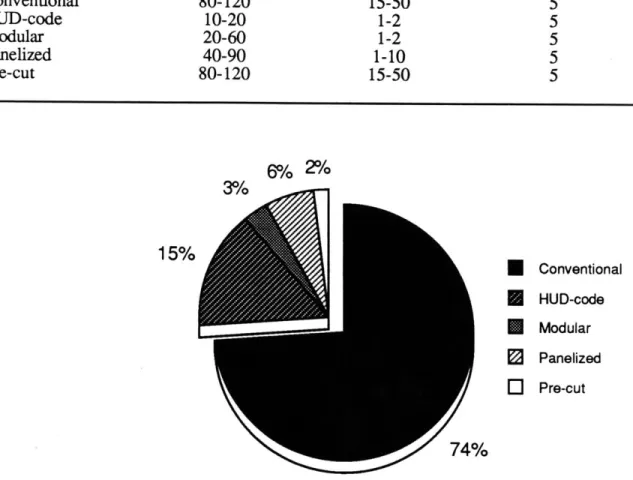
Current technology in prefabricated residential construction in the U.S.Manufactured housing is typically divided into four groups: HUD-code (mobile homes), modular (also called sectional), panelized and pre-cut. Table 2.2 shows the construction time, close-in time and crew size for these systems. Figure 2.2 shows the total market share of single family detached houses for each building system. The market
share of these prefabrication systems is far from uniform across the U.S. [Hallahan, 89]. Modular market share ranges from less than 1% in the West to 7% in the Northeast. Panelized construction ranges from 4-7% in the West to 25 -29% in the Midwest and Southeast. These numbers reflect the increased applicability of these systems under market conditions more suitable to their use. The higher local numbers suggest that overall
increased market share is possible as conditions across the U.S. change.
2.2.1 HUD code mobile homes
HUD-code houses are homes built according to a code implemented by the
Table 2.2 : Approximate construction time and crew size for five methods of construction.
A building is considered weathertight, or tight, when all exterior sheathing, windows and
doors have been installed.
Days under Days to Crew size
construction weathertight (site work only)
Conventional 80-120 15-50 5 HUD-code 10-20 1-2 5 Modular 20-60 1-2 5 Panelized 40-90 1-10 5 Pre-cut 80-120 15-50 5
6% 2%
3% 1 Conventional HUD-code Modular PanelizedE
Pre-cutFigure 2.3 : U.S. market share of homebuilding systems 1987 Source: [LSIIF.W. Dodge, 881
Safety Standards in 1976 for mobile-type homes. This code supersedes state and local codes for this type of housing. Most HUD-code houses include a metal chasis in the floor and either light gauge metal or wood framing. They can be single wide, leaving the factory
100% complete, requiring only utility hook-ups, or double wide, requiring one to three weeks site finish work. They are sold through local dealers and usually resemble plain one story stick built houses.
2.2.2 Modular
Modular (or sectional) single family houses are commonly built up of two to six large three dimensional boxes. These sections, or modules, are usually stick framed in a factory, complete with fixtures and finishes. They are then stacked vertically or joined side by side in a variety of configurations at the site. Three to eight weeks of finish (or button-up) work is then required. Modular homes are usually assembled into single family detached houses but can also be assembled into multi-family housing up to three stories high.
2.2.3 Panelized
Panelized home packages are pre-designed home packages that come to the site in the form of wall and floor panels and either roof trusses or panels. They may also include modular utility cores. The wall panels are often large and may comprise the whole side of a one story house. Section 2.3 provides a more detailed discussion about the types of panels available.
2.2.4 Pre-cut
Pre-cut house construction is relatively uncommon. A pre-cut home consists of conventional construction materials that are cut and labeled in the factory, shipped to the site, and installed using mainly standard practices. There is a very low degree of prefabrication and therefore the site work duration does not differ dramatically from
conventional construction. Log Homes, once a very popular house kit, would fall into this category.
2.3
Current residential panel technologyThe following is a brief summary of current technology in panelized residential construction in the U.S. Residential building panels can be divided into two broad categories -stick-framed panels and foam-core panels.
Stick-framed panels are similar to conventional construction in that the materials and assembly details are nearly identical. The difference is in where the labor is performed. In this type of construction, the wall, and occasionally floor and roof sections are
prefabricated in a factory and brought to the site whole. These wall panels are often very large and may comprise the entire length of a one storey house. The floors are often pre-framed into panels as well in stick pre-framed panelized construction. The roofs, however, are usually not pre-framed. They are either conventionally framed with rafters or, more likely, built with trusses.
Within this type of panel are two classes -open-wall panels and closed-wall panels. These terms refer to the degree of value added to the prefabricated product. Open wall panels contain the framing, exterior sheathing and windows. Closed wall panels also include electrical work, plumbing work, insulation, exterior siding and the interior sheathing (usually gypsum wall board).
Two major problems, one political and one technical, have plagued attempts at closed wall panel construction. Since site inspection by the local building official is impossible when the walls arrive closed-in, arrangements must be made for a third party inspector to inspect the walls in the factory. Most states have legal provisions for this,
however initial approval of a manufacturer's system can take 6 months and approving a change in the system takes 1 to 2 months. This causes a manufacturer to be slow to
respond to the market. The technical problem is that there is a greater potential for shipping and erection induced damage to the more delicate interior finish materials of a closed wall panel. Of the approximately 130,000 stud-framed panel homes built in the U.S. each year from 1984 to 1988, only 2% were closed wall.
Stressed-skin panels are a version of the stud-framed panel. They are a type of panel in which plywood (or other sheathing material) faces are glued firmly to both sides of a frame (usually 2x dimensional lumber). The skins and frame work together resulting in a panel stiffness much greater than that implied by its parts. Structural foam core sandwich panels (see below) are also sometimes referred to as stressed-skin panels.
The second category of panels is foam-core panels. For a more in depth discussion of foam core panels an excellent source is Foam-Core Panels & Building Systems:
Principles and Practice Plus Product Directory by Stephen Andrews [Andrews, 88]. This category can be further divided into structural sandwich panels with faces and foam panels incorporating framing members with no faces. Here, the discussion will focus on the more common structural sandwich panels with faces.
Structural sandwich panels consist of a foam core sandwiched between two faces (figure 2.4). The foam core can be either polystyrene (EPS -expanded or extruded) or urethane (polyurethane or polyisocyanurate). Polyurethane and polyisocyanurate are two very similar chemicals, here both referred to as urethane. They are closed cell plastic foams that contain low conductivity freon gas in the cells. Core densities for both urethane and EPS are commonly one to two pounds per cubic foot. The panel faces are often plywood, waferboard or oriented strand board. In the case of non-load bearing curtain wall panels used to clad timberframe (post and beam) homes, drywall is often used on the interior face. In bending, a foam core sandwich panel is structurally analogous to an I-beam. The low density core functions as the web and the high density faces as the flanges (see figure 2.5)
Exterior face plywood waferboard OSB
polsarne Panel .eam
r to Interioro
flexle. hemotcomonrethod Cofss-stectin pfal togetihe iswthaanee.Terlr
man vrson o teplneasilusraedinFaigr 2.6. e
pakgs.FaSc andwich pansaros fenueda-cmoentam uso
desinds homesan, thesaeey exlotngiffigege infsherian flexibidey cOsierallel
sytesae icomepaelsalwgeateinflxblt, in that theydnousalicueth for r eighofoo build ng u its an b sit cut ith onve tion l to ls a d theconn ctio.sysem.i.ver
flexble.The ostcommn mehodof fstenng anel togthe is ith spine.Ther.ar many ersios of he spine a illutrate.in.fgure..6
The sud-famedpanel desribe aboe aremostofte use.in.pe-deigne.hom packages.~~~~~... Foa core sadwc pael are. mos ofesdaopoetncso
desiged hoes, hereb explitin thei hig degre.of.esig.flexbilit. Ovrallpane sytmprompltyee, intatteyd .ntusal.icud.hefoo.r.of
Figure 2.6 : Foam-core panel joints currently in use Source: [Andrews, 90]
2.4
Components in residential construction, or The value-added approach to homebuildingThroughout the Twentieth Century, housing construction has undergone large changes. Individually, these changes have not been sudden or revolutionary, but rather have been continuous and evolutionary. The change in the U.S. residential construction industry can be described as a trend toward the use of building components fabricated off site. Homebuilding has moved from a custom, labor intensive industry to a largely industrialized factory driven process. Housing construction, as perceived on the building site, is today merely the last step of a manufacturing process which involves the
manufacturing and assembly of a large number of parts of varying complexity. Most of these parts come from industrial manufacturing facilities and are referred to here as building components.
In the Nineteenth century, except for a small number of prefabricated home kits sold from catalogues, most residential construction was custom built on the job site by skilled craftsmen or the homeowners themselves. These workers constructed a dwelling from the most basic of raw materials -raw lumber, glass, stones, etc. Windows were glazed, doors were fabricated and hung, fireplaces were built brick by brick, all on a one by one basis.
As industrialization entered the housing industry this way of building changed. Standard size lumber, plywood and sheetrock were some of the earliest products to appear. One of the first high value-added components to be built off site was the window. The Andersen Corporation introduced into North America the first pre-assembled window in 1932. It could be made cheaper and with higher quality in a factory. Buying the windows pre-made was much easier and quicker for a builder to do, and it eliminated a jobsite skill that the builder previously needed. Kitchen cabinets is another good example of
the site. Now they are usually mass produced in factories and shipped through distributors to the site, where they are installed. Componentization progressed to eventually include many parts of the house (table 2.2). Now, it is possible to build nearly an entire house by assembling pre-fabricated components, both off the shelf items and custom factory-made parts. Many people in the residential construction industry believe that components are the most promising concept for decreasing the cost and increasing the performance of housing.
Table 2.2 : Components in use today and the site method or trade they replaced.
Component Replaced trade or method
windows and skylights glazier
pre-hung doors hanging doors
staircases highly skilled carpentry
roof trusses rafter framing
floor trusses joist framing
Engineered wood structural built-up dimensional lumber members such as LVL, Glue-Lam,
Para-Lam, wood I-beams
pre-fabricated
fireplaces and chimneys bricklayerplumbing trees plumbing site work
electrical octopuses electrical site work
envelope parts, wall & roof panels framing, sheathing, drywall and insulation
pre-fab
trim and moulding pieces custom mill workkitchen and bathroom cabinets cabinet craftsmen moulded bath tubs & shower stalls plumbing, tile setting countertops and other built-in custom mill work
furniture pieces
These components are sub-assemblies that come to the construction site ready to be installed into the building shell. Components are usually parts of the building that have a concentration of value in them; in either materials or labor. Since they are fabricated off-site in a factory with a controlled environment, they can use manufacturing methods and equipment not available on a construction site. Some of the products built in this way,
such as windows and plumbing fixtures, are standardized in dimension and in their interface with the building frame. Others, such as roof trusses and stairs, are customized according to the plans of the house. This method of construction can be termed
construction-by-installation. Components reduce the skill requirements required at the job site. The numerous trades once required to serve the builder, have moved to the factory and builders have became installers of factory-fabricated components and pre-finished assemblies. The overall strategy of componentization is to reduce the fabrication and assembly requirements at the job site (figure 2.7).
Fabrication W Assembly & Installation Component Value $$
Figure 2.7: Componentization
One reason for the acceptance of pre-fabricated components was that builders could take an "a la carte" approach to using them. Componentization does not try to impose a rigid, or closed, building system on the builder. Rather, the components are all designed to be compatible with the standard residential construction method of the past fifty years -the 2x stick frame. A builder can use or not use components for any part of the house
depending on his or her skills, the customer's desires or the current market situation. Component use fluctuates with general market conditions. In a slow period builders will often choose to not use certain components because cheap labor is available
and they may want to retain their regular crew by keeping them working on a job for a longer time. In a busier period, a builder may use components that they would normally not use, due to a shortage of skilled labor or a need to hasten the construction process.
Another argument supporting the increased use of components in residential construction stems from the growing congestion of America's urban and suburban areas. Large tracts of land for housing are becoming increasingly rare. They are only to be found in some areas of the West. Subdivisions of hundreds of lots have historically enabled builders to set up very efficient construction operations in an "inverse assembly line" method. Specialized crews move from house to house repeating the same task of framing, siding, roofing, drywall, etc. Some builders even set up prefabrication plants on site for a specific project. As large developable tracts have become less common and consumer preference has leaned toward more individualized houses, builders have been forced to abandon this efficient way of site building and high density, scattered-lot development (lots suitable for one to a dozen homes) is becoming the predominant way of homebuilding.
Factory produced components are better suited to scattered-lot development. The increased efficiencies once enjoyed by the large-tract builder are being transferred into local or regional factories. Standardized components can be shipped to scattered sites as easily as they can be sent to large developments. These factories require greater capital
investment in the short term but will be able to provide components for more homes in the long run.
In short, there are three fundamental differences between components and the other four building systems (HUD-code, modular, panelized and pre-cut) that are responsible for the greater growth of components [Toole, 90]:
- The nature of the other systems being complete house packages limits their architectural design flexibility beyond acceptable bounds in many markets. Contrarily, the "a la carte" selectability of components provides great design flexibility.
* Components have the optimal amount of work done in the factory given the manufacturing technology and site labor situation today. Modular and mobile homes have too much, resulting in a lack of design flexibility and high shipping costs, and pre-cut have too little, its assembly being little different from stick framing (section 4.1.4).
- Components benefit from systems improvement while the others still rely largely on conventional construction materials and assemblies.
CHAPTER 3
Design goals of roof systemThis section describes the characteristics that a panelized roof system should have to be successful in the marketplace. As explained in chapter 1, the IHCTP decision to work on a prefabricated roof system preceded the start of work on this thesis. A more complete explanation of this decision is contained in chapter 4.
The design goals stem from the earliest ideas of the IHCTP researchers; ideas that were gradually clarified, refined and solidified as time and study progressed. The
characteristics focus on meeting consumer expectations, code issues and builder concerns and are based largely on competing favorably against the major competing system;
conventional stick frame construction, either with rafters or trusses.
The goals are based on the constraints imposed by market forces and on actual physical factors. The market related issues include:
- Architectural design flexibility.
- Aesthetic requirements of finishes and details.
- Public perception of the system as influenced by the performance of earlier pre-fabrication building systems and methods.
- Market position: cost and quality in relation to competing systems.
- Structuring system advantages to benefit the party that decides which building system to use. This decision maker may be the owner or developer, designer or contractor.
The physical factors include: - Ease of manufacture.
- Transportation size and weight limits. - Erection size and weight limits.
" Construction time
- Compatibility with other building systems. - Fire code compliance
- Thermal performance. " Structural performance
" Preventing moisture and heat induced damage to the roof.
The system must equal or surpass minimum standards in these areas to be successful. Where applicable, an attempt is made to determine these standards quantitatively.
The market issues, physical factors and minimum standards combine to form a detailed problem statement. It is important to formulate this problem statement early in the design process as discussed in the evaluation of the design process, section 8.2. The design goals themselves are summarized in section 3.14.
3.1
Architectural design capabilitiesThe roof panel system is a pre-fabricated building system. One of the major complaints with pre-fabricated building systems over the years has been that they all look alike and lack individuality (section 3.4). This complaint has hindered wider acceptance of pre-fabricated building systems. It will be important for the panelized roof system to avoid this trap. This can be done on three levels; the overall forms, the finishes and the details. These are discussed in sections 3.1 and 3.2 and 3.3 respectively.
In the realm of forms, the system must be able to form the range of complex roof geometries that are used on common production built homes in the U.S. These include
hips, turn gables, dormers, a range of slopes and spans and openings for skylights and other penetrations. In short, it should be able to do all things that a conventional rafter framed roof can do while imposing the fewest restrictions on the designer.
The system can accept some restrictions in terms of the flexibility of size and positioning of these elements. For example, the system must accommodate turn gables but it would be acceptable to constrain the width of the turn gable to a rib spacing multiple and to constrain its spacing such that its center-line falls on a panel to panel joint.
Extremely complex roofs incorporating many intersecting gables at varying slopes with turrets, cupolas, etc. are rare, especially in production built houses. Therefore, the capability to build these types of roofs is deemed to be unnecessary for this system.
3.2
Aesthetic requirements - finishes:The interior and exterior finishes of the roof panels are an important consideration. Currently the standard finish on most houses is gypsum wall board, taped and painted on the inside ceiling surface, and asphalt shingles on the exterior roof surface. Other less common roofing materials are wood shakes, clay or concrete tiles, aluminum shingles and seamed metal sheets. For the interior, wood paneling and acoustic tiles are also used. As a basic guideline, a ceiling surface in a living area demands a high level finish whereas a semi-finished or unfinished surface is acceptable in an attic or other non-living area.
The finish strategy of the-system will be governed by market acceptance. As it is very difficult to predict whether a new type of finish will or will not be accepted and it is unacceptable to restrict the choices of finishes available on the roof system, a semi-finished (suitable for painting) or unfinished (requiring drywall) should be the basic panel surface1.
3.3
Aesthetic requirements - detailsThe connection and joining details between materials and components is a good way to measure the quality of craftsmanship and construction in a house. Well thought out, good fitting and attractive details are an indication of quality construction and probable longevity of the work, and will be perceived as such in the marketplace. This is true for both interior and exterior finish details.
There should be a variety of ways to attractively detail the completed roof system to encourage individuality among dwellings as discussed in section 3.1. These ways should include the popular architectural styles that the market demands, perhaps utilizing pre-fabricated trim components. Preferably, the system will allow the designer or builder some latitude in detailing the trim. This can be done by providing a base to work from rather than a limited choice of pre-determined options (see 3.11 -compatibility). Likewise, the interior should support flexibility of choice in trim style and materials.
Homeowners place too great an importance on interior details for the their aesthetics to be compromised. The details should not reveal the nature of the roof system at first glance; that is, the technology should be transparent to the casual observer.
3.4
The public's perception of prefabricated constructionFor the panel system to be successful, it will have to combat the public's
longstanding negative perception of prefabricated construction. Negative perception was cited as the number one soft barrier to prefabricated construction in a 1988 survey of
builders [Crowley, 88]. It connotes boring, repetitive design and shoddy workmanship in most American minds. The perception that prefabricated homes are shoddy and poorly built started after World War II. A major factor contributing to this perception was that pre-fabricated construction on a large scale was first attempted with low-cost housing. In this situation, the repetitive design and lower quality materials used was more a function of the low cost nature of the housing than of the prefabrication. In the ensuing years, the quality of construction and design of factory made houses has risen to, and above, the average site built conventional house. More recently, some manufacturers have begun to use the advantages of a controlled factory environment to make high quality, luxury homes. This has begun to change the public's perception, but there is a long way to go before pre-fabrication is associated with quality building.
A positive perception of prefabrication is prevalent in some foreign countries, particularly Japan and Scandinavia. In Japan, pre-fabrication started at the high end of the market with luxury dwellings. The ensuing association of pre-fabrication with high quality
made consumer acceptance of pre-fabrication at the mid and low ends of the market much easier.
To combat the negative perception in the U.S., prefabricated building systems are often touted as using high quality materials and as being energy efficient. In addition to this, the panel system should be promoted as an alternative building component or product rather than as a prefabricated roof. Emphasis should be placed on the fact that the system plugs into other construction methods used in North America, Europe and Japan (section 3.11). Also, the importance of quality control and quality detailing is hightened as this system will be evaluated prejudicially by consumers and builders.
3.5
Market position of panel systemCurrently, while there is wide regional variation, 65% of single family detached housing starts in the U.S. utilize roof trusses [LSI/F.W. Dodge, 88]. Most of the
remainder use rafters. Costs of these systems depend on the degree of design complexity. The panel system is expected to be more cost competitive with rafters and trusses at the
medium to high end of the design complexity scale.
Whereas rafters and trusses are highly sensitive to design complexity, the
prefabricated panel system is expected to be less sensitive. The site work should be only slightly more difficult and the automated, flexible panel manufacturing process (section 3.7) will not be highly sensitive to varied panel shapes. Costs per square foot for rafter, truss and foam-core panel roofs are shown in figure 3.1 for simple roofs and complex roofs. Complex roofs include at least one turn gable and hip. Figure 3.1 compares these
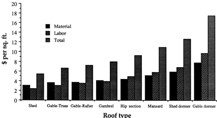
system's costs to a projection of what the panel system designed for the POC structure by the IHCTP may cost, based on materials and manufacturing cost predictions [Parent, 91]. Figure 3.2 shows cost broken down into material and labor for trusses, and seven types of
roof forms built with rafters. If the panel system is significantly less expensive than rafters for the more complex designs, this should provide the panel system with an opportunity for early market acceptance.
Figure 3.4 illustrates the positions of truss and rafter roof systems and the potential position of the roof panel system with respect to five important factors. These five factors are major factors influencing the selection of competing building systems in the
marketplace.
The panel system should be positioned in the market such that it is as close as possible to trusses in cost and significantly cheaper than rafters. This range is illustrated in
figure 3.4. In this position, its advantage over trusses in the area of design flexibility will be apparent. The move from trusses to panels will be made to recover roof cavity space
N Simple roof
4
Complex roof
0'
Rafter Truss Foam panel Ribs
Figure 3.1 : Costs offour roof systems for simple and complex roofs
Source: [Parent, 911
* Material
* Labor
* Total
U.N./
dormer Gable dormer Shed Gable-Truss Gable-Rafter Gambrel Hip section Mansard Shed
Roof type
Figure 3.2 : Residential roof cost for roof parts of increasing complexity Source: [R.S. Means, 1989], compiled by John Crowley
'-I
'4-&
U, I-i 20 -18-
16- 14-12-
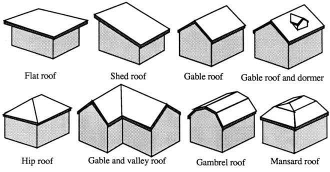
108 - 6- 4-2-... ...... Flat roof ... ... ... ... ... ... :K j: ... Hip roof
Figure 3.3 : Common roof forms
Factor
Design constraints Space use constraints Construction skill level Construction time Construction cost
P = panel system
Low (good)...High (bad)
R ... P...T
P ... R ... T P ... T... R P ... T . ... R T ... P...R
R = rafter construction T = Truss construction
Figure 3.4 : Market position of competing roof systems (construction
factors
assume medium complexity)and increase design flexibility with only a slight cost premium. The move from rafters to panels will be made for cost and time savings with a minimum sacrifice of design
flexibility. Performance benefits will be realized in both moves.
.... .. ... ... ... ... ... X % ... ... ... ... ................% . ... .... .% ...
Shed roof Gable roof Gable roof and dormer
... .. ... ... .... ...... ... ... ... ...... ... ...
3.6
Benefit to the decision makerThere are three principal players in the traditional home building process -the owner/developer, the designer and the builder. The designer is often eliminated as a separate player in the case of production built houses. Each player has different, and sometimes conflicting goals which stem from different motivating factors. The advantages of the roof panel system should be structured so the perceived benefits are most strongly directed at the player that will decide what building system to use for the roof. Of course in the long run, the end user should actually benefit.
The owner/developer is motivated most strongly by cost considerations and
secondarily by quality and speed of construction. The designer is attracted to a system that delivers the best performance and design flexibility. The builder is motivated by
convenience and construction speed. The owner/developer is usually the final decision maker but may be influenced in the selection of a building system by the designer and especially by the builder.
An example of a panel building system where the system advantages did not match the interests of the decision maker is that of Cheney Building System in New Berlin, Wisconsin. The panels in this system, called "Chase Thermo-Panels", used a cam lock fastener in the panel to panel joint (see figure 2.6). This method provided great
convenience to the builder but did not translate into increased savings for the owner2. The Chase cam-lock panels are no longer made due to the prohibitive cost of the cam-locks.
The advantages of the panel system are to be structured to benefit the
owner/developer by keeping costs low and improving performance. Also construction time will be kept down to further savings. The design goals are structured toward these ends.
3.7
ManufacturingOne of the main reasons for prefabricated construction is to take advantage of manufacturing techniques possible in a controlled factory environment. The roof system components should be conducive to high volume production using "lean" manufacturing techniques. "Lean" manufacturing, in the context of the roof panel system, is a flexible technique using automation to minimize the inventory and line workers needed. This should enable quick response to orders -approximately 2-3 days from order to fabrication and shipping. For the short term solution, production machinery should use existing technology.
All roofs should be made to order. This lesson has been learned the hard way in the industry. Sterling-Homex is one example of a prefabricated homebuilder that was unable to carry their large inventory of homes, causing them to go out of business.
The level of capitalization possible, and hence automation, is determined by the plant's volume, which is a result of its market share and market area. Market share is determined by, among other things, price, which is strongly affected by the cost of production which in turn is determined by the manufacturing technology employed. This paradox is a major factor inhibiting the capitalization of housing component manufacturers. Therefore, the system should be able to begin manufacturing with a minimum of
automation, adding more as market, and revenue, grow. This may be done by initially focussing sales at the high end of the market.
The limited market area of the roof panel plant is a result of the the limited delivery range possible with large, prefabricated building elements. A radius of approximately 350 miles may be the maximum range possible as explained below in section 3.8.
3.8
TransportationIn order to be transported along America's roads, the panel components are restricted to certain sizes. A truck trailer must fit within a specified envelope according to
federal law. This envelope is 8'-6" wide by 13'-6" high by 53 feet long. A standard flatbed truck trailer rises 4 feet off the ground, leaving an envelope size of 8'-6" by 9'-6" by 53 feet for the cargo. There are provisions for transporting larger loads -up to 14 feet wide by 14 feet high by 60 feet long. These provisions vary from state to state and depend on the size of the load. State laws may restrict hours of travel for oversize loads (usually to daylight hours) or restrict the roads they may be driven over. Special permits, at about $50
per state and escort vehicles, at about $.85 per mile, may be required. Two escorts may be required for loads wider than 13 feet3. These restrictions and the variations between states can make interstate commerce in modular homes or other large items very complex. It would be costly to have a truck stopped at a state line because of some oversight, halted in a state when the sun goes down or forced to take a roundabout route over secondary roads. According to an Operation Breakthrough transportation study referring to truck shipment of building components, "Costs, associated with circuitous routing, increase directly with the additional mileage" [U.S. HUD, 75]. For these reasons; excessive cost, site accessibility and scheduling restrictions, it was deemed desirable to design a system whose components were transportable within the standard truck envelope.
In addition to the dimensional constraints to transportation posed by state and federal law, the market range of a factory is limited by the economics of transportation. Basic transportation costs for regular size loads are approximately $2.50 per loaded mile4.
3Communication with Home-Run Shipping Company 4ibid.
![Figure 2.1 : Conventional platformframing Source: [Ramsey/Sleeper, 81] 19 TWO 2X4'S -SHEATHING_STUOSTUDS-2X4SOLEPLATECROSS](https://thumb-eu.123doks.com/thumbv2/123doknet/14685105.560052/19.918.117.760.219.928/figure-conventional-platformframing-source-sleeper-sheathing-stuostuds-soleplatecross.webp)
![Figure 2.6 : Foam-core panel joints currently in use Source: [Andrews, 90]](https://thumb-eu.123doks.com/thumbv2/123doknet/14685105.560052/27.918.107.774.211.875/figure-foam-core-panel-joints-currently-source-andrews.webp)

![Figure 4.2 : Conventional roofframing Source: [Ramsey/Sleeper, 81]](https://thumb-eu.123doks.com/thumbv2/123doknet/14685105.560052/61.918.153.739.121.1008/figure-conventional-roofframing-source-ramsey-sleeper.webp)
