The Design of a Fluidized Bed for Testing of a
Robotic Burrowing Device which Mimics Razor
Clams
by
Daniel Scott Dorsch
Submitted to the Department of Mechanical Engineering
in Partial Fulfillment of the Requirements for the Degree of
Bachelor of Science in Mechanical Engineering
at the
MASSACHUSETTS INSTITUTE OF TECHNOLOGY
June 2012
@
MMXII Daniel Scott Dorsch. All rights reserved.
ARCHIVES
MASSACHUSETT~S INSTr"TEOFTECHNOLOYY
JUN 28 2012
LIBRARIES
The author hereby grants to MIT permission to reproduce and
distribute publicly paper and electronic copies of this thesis document
in whole or in part.
Author ...
...
Department of Mechanical Engineering
7<
May 11, 2012
Certified by...
Associate Professor
Anette E. Hosoi
of Mechanical Engineering
Thesis Supervisor
Certified by...
...
Amos G. Winter V
Postdoctoral W
te with the MIT-SUTD IDC
is Supervisor
Accepted by .
...
...
John H. Lienhard V
Samual
.s Professor of Mechanical Engineering
The Design of a Fluidized Bed for Testing of a Robotic
Burrowing Device which Mimics Razor Clams
by
Daniel Scott Dorsch
Submitted to the Department of Mechanical Engineering
on May 11, 2012, in Partial Fulfillment of the
Requirements for the Degree of
Bachelor of Science in Mechanical Engineering
Abstract
This thesis reviews the design of a fluidized bed test setup for testing digging kine-matics of RoboClam, a burrowing device based on Atlantic Razor Clams. This test bed allows for in-lab testing in an environment covered by water, eliminating the need to test in the mud flats where razor clams live. Between each RoboClam test, water is pumped through a distributor plate, which suspends and fluidizes the glass bead media, leading to redistribution of the substrate and unpacking. The new fluidized bed system has two key improvements over the current system. It improves the re-distribution that is needed between each test to reset the substrate. Before each test it also unpacks the beads, which prevents packing over time created by the current vibration redistribution system that causes changes to the soil mechanics. This sys-tem will enable continued testing of the current RoboClam device and facilitate the development of the next generation burrowing device.
Thesis Supervisor: Anette E. Hosoi
Title: Associate Professor of Mechanical Engineering Thesis Supervisor: Amos G. Winter V
Acknowledgments
This work was sponsored by the Batelle Memorial Institute of Columbus, OH, and Bluefin Robotics of Cambridge, MA.
I would like to thank my family and friends who have made receiving an education at MIT possible. My parents and three brothers have had a large impact, and have been by my side at all points in my life. I would like to thank my father Jeff Dorsch, Kevin Engstrom, and Greg Thomas who inspired me to pursue engineering. I would also like to thank Amos Winter who motivated me to work hard and apply knowledge gained in class to real world applications. It was his inspiration which transformed me from a student to an engineer and lead to my desire to pursue a graduate degree in engineering. I would also like to thank Professor Anette Hosoi and Professor Doug Hart for their assistance and advice with this project.
This project would not have been possible without help from Amos Winter and Edgar Salazar assembling this complex system and making it function correctly. Spe-cial thanks to Mark Belanger and Dave Dow for their assistance in creating parts for this project.
Contents
1 Introduction 13
1.1 Razor Clam Digging Dynamics . . . . 14
1.2 RoboClam Digging Apparatus ... ... 14
1.3 Current RoboClam Testing Methods . . . . 15
2 Design Conceptualization 17 2.1 Important Constraints ... ... 17
2.2 Functional Requirements . . . . 18
2.3 System Overview . . . . 18
2.4 A nalysis . . . . 19
2.4.1 Volume Change and Packing Fraction . . . . 19
2.4.2 Fluidization Flow Rate . . . . 20
2.4.3 Pressure Drop . . . . 21
2.4.4 Exit Pipe Flow Rate . . . . 24
2.4.5 Plate Bending . . . . 25
2.4.6 Wire Mesh Strength . . . . 26
3 Design Implementation 29 3.1 Overall Design For Manufacturing Considerations . . . . 29
3.2 Benchtop Fluidization System . . . . 29
3.2.1 System Layout . . . . 30
3.2.2 Flow Rate Determination . . . . 31
3.3.1 Drum Selection . . . . 32
3.3.2 Distributor Plate Design . . . . 33
3.3.3 Distributor Plate Mounting . . . . 34
3.3.4 PVC Spreaders . . . . 35
3.3.5 Hose and Fitting Selection . . . . 35
3.3.6 Pump Selection . . . . 36
4 System Functionality 39 4.1 Testing the System . . . . 39
4.1.1 Flow Rate . . . . 39
4.1.2 Draining . . . . 40
4.1.3 Unpacking and Redistribution . . . . 41
4.2 Future W ork . . . . 41
4.2.1 Final Steps . . . . 41
4.2.2 Robot Integration . . . . 42
List of Figures
2-1 This figure shows the layout of the full fluidized system. Water flows from left to right across the system in a continuous loop. . . . . 19
2-2 The flow through the system can be modeled as a circuit, with fluid flow as current, and fluid resistances comparable to electronic resistances. The resistance through the distributor is the resistance through the spreaders and the distributor plate. There are unique pressures at each point. The pressure at the bottom of the drum must be great enough to support the weight of the beads in a fluidized state. Note that Ohm's law does not hold for this system due to inertial effects of the water, but this schematic is an illustration that helps with calculating pressure at each location . . . . . 22
2-3 This figure shows the curve (E) for the flow rate versus pressure for the 1.5 HP AMT pump that was selected [1] . . . . . 24
2-4 This figure shows the bending of the 1/4 inch plate with a 4000 newton load applied. The displacement in this case is about 2.4 mm which is not large, but not insignificant. . . . . 26
2-5 This figure shows the bending of the 1/4 inch plate with a support added in the middle. In this case the maximum displacement iss only about 0.35 m m . . . . 27
3-1 This figure shows the benchtop fluidized bed that was used to deter-mine the flow rate needed for fluidization. The tube from the pump can be seen entering the bottom of the system. Water flows upward through the valve used to control flow rate, then into the clear visual-izer section. Glass beads rest on the wire mesh, mounted between two pieces of black plastic. The system is mounted to an aluminum bar to hold the system upright, seen running up the right side of the visualizer. 30
3-2 This figure shows various states of fluidization. A) shows the beads at rest, with the lowest void fraction. B) has a void fraction of near 0.51. C) has the highest flow rate, and an even higher void fraction. The turbulence in the water flow for the highest flow rate case can be seen
by the uneven surface of the beads at the top of C. . . . . 32
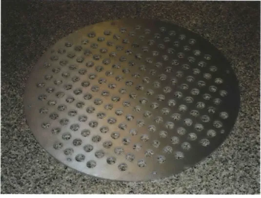
3-3 This figure shows distributor plate after it has been waterjetted. . . . 34
3-4 This figure shows the sandwich architecture of the distributor plate. The 1/4 inch aluminum support plate holds the weight of the system. Wire mesh rests on this supporting the beads. A hold down plate is added on top of the mesh to prevent it from moving during pump
operation . . . . 35
3-5 This figure shows the PVC spreaders which cause a uniform pressure
distribution in the bottom of the drum. Holes along the length let water out evenly across the bottom of the drum, creating an even
pressure distribution. . . . . 36
3-6 This figure shows pump and manifold which brings water to the four PVC spreaders inside the drum. Water flows into the pump on the left. A shutoff valve allows for controlling the flow rate. Water then
4-1 This figure shows the fluidized bed system in its nearly completed state. Water flows out the top of the drum through the angled drain into the rectangular collector. From here it flows through the large tube into the pump. Four smaller black tubes enter in the bottom of the drum. The drum clean-out port can be seen in front, which is also used for emptying the system. . . . . 40
Chapter 1
Introduction
RoboClam is a device that is being developed by researchers at MIT to produce a system for efficient, lightweight burrowing technologies. RoboClam is a biologically inspired burrowing device based on Atlantic Razor Clams, Ensis directus. This animal was selected for its large size (enabling easy replication as an engineering device), its low power usage for burrowing (approximately 0.21 .), and simple one degree of freedom hinge. Ensis directus was selected as the animal to model a digging device for several important reasons. The animal digs quickly, moving downward at roughly one centimeter per second. It is also native to New England, so it can be easily obtained and studied. RoboClam is designed for use in littoral regions, and has a variety of potential applications, such as anchoring for underwater vehicles or buoys, digging for mines, or undersea cable laying [2].
Razor clams burrow by creating a fluidized failure region in the area directly surrounding their body. Quick motions of the animal's body create this quicksand fluidized region, significantly reducing the drag force associated with digging. Digging mechanics of the razor clam are being studied, with an attempt to develop engineering principles correlating digging kinematics to performance. The Ensis method of dig-ging results in an order of magnitude improvement over current means of burrowing
in ocean substrates [2].
This thesis discusses the design of a fluidization bed for testing RoboClam in a laboratory setting. The goal of this system is to uniformly redistribute the glass bead
soil medium which is used in the lab to simulate real soil. This uniform distribution
results in a consistent environment for testing the robot, preventing the development of a soft spot in the place where the robot digs. Currently a vibrator motor is used to repack the beads after each round of digging, but there are issues with the vibration system such as substrate packing over time, which do not exist with a fluidized bed system.
1.1
Razor Clam Digging Dynamics
Razor clams dig into the soil with a four stage motion [2-5].
1. The clam's soft tissue foot extends to uplift the shell.
2. The shell halves rapidly contract, and the foot inflates to act as an anchor.
3. The foot muscles contract to pull the clam downwards.
4. The shell expands.
Amos Winter, a Post-Doctoral Research Associate with the MIT-SUTD Interna-tional Design Center, developed a particle image velocimetry (PIV) tank to observe razor clam burrowing in transparent substrates. Analyzing the PIV data, Winter determined the shell can contract quickly in the substrate. Inward motion draws water into the region and causes a localized failure region in the soil, resulting in a fluidization area within 3 radii of the animal's body. This fluidized effect creates a significant reduction in drag on the animal when it digs [2].
1.2
RoboClam Digging Apparatus
Using knowledge gained from PIV tests, Winter constructed an actuator system and end effector to mimic the motions of a razor clam [2]. The actuation system is pneu-matic, powered by a scuba tank. At the end of the piston attachment is an end effector, which consists of a small metal piece which can be opened and closed to
replicate the motion of a real razor clam. The top piston of the actuation system controls the open-close motion of the end effector with a titanium rod which passes through the lower piston. The lower stacked piston is a hollow rod, double-ended piston which controls the up and down motion of the end effector. This dual actua-tion system allows simultaneous independent moactua-tion in the open-close and up-down directions.
1.3
Current RoboClam Testing Methods
There are currently two methods for testing the RoboClam. The first method is testing the robot in the mud flats, the razor clam's natural habitat, which is difficult for several reasons. Testing must be done at low tide when the muddy area is exposed. The tide is typically this low only once a month for a few days, at inconvenient times (such as 3 am). It is also time consuming and expensive to travel to Gloucester,
MA, to collect data. Testing in the ocean also requires a great deal of methodical
preparation, since any mistakes in the robot's operation can yield faulty test data. As such, an in-lab system was developed for testing RobClam. This system con-sists of a 30 gallon drum with the robot mounted on top. The drum is filled with
20-30 mesh soda lime glass beads (0.595 to 0.841 mm in diameter). These beads are
perfectly round and simulate real soil. There are difficulties associated with digging in a relatively small container, as effects of the finite space are encountered. Thus, it is actually more difficult for the robot to dig in this idealized substrate (round beads) than in the mucky soil in the mud flats.
Each time the robot digs, after it returns to the top, a hole is left in the soil. In the ocean, the robot is moved on a sled to a new location for each new test. In the
lab, this is not possible since the robot is fixed to the drum. A system was devised to evenly redistribute the beads between each test. A vibrator motor attached to the outside wall of the drum operates between each test to repack the beads. While this system works well to redistribute the beads, there are a couple of issues with vibrator based redistribution. The first is the state of the beads. As the motor vibrates,
it causes the beads to become packed. Since the beads are in a small drum, it is very difficult for the robot to dig effectively in this highly packed environment with little space for the beads to expand radially when the robot is inserted in the center. The second issue is the increase in packing of the beads over time. When tests first begin, it is comparably easy for the robot to dig. Over time, it is believed that the beads become even more packed and decrease performance of the robot. Hence, it is extremely difficult to compare tests from the beginning of a testing sequence to those at the end, due to changes in the substrate properties over time.
Chapter 2
Design Conceptualization
The design of the fluidized bed experimental setup was guided by studying existing fluidized bed design considerations, spreader methods for evenly distributing gases and liquids, and the constraints and functional requirements of the RoboClam system.
A benchtop fluidized bed system was developed to verify the design. The specifics of
this system will be discussed in the next chapter.
2.1
Important Constraints
The key constraints on the design for the fluidized bed are as follows:
1. The height of the bed is limited. Using a commercially available drum is strongly
desirable, which is only available up to a certain height.
2. The overall size of the system is limited by the available space in the lab.
3. The system should be made from components that can be easily fabricated in a
rapid fashion. The goal is to aid in testing a robot; it is not a new robot being created.
4. The system must operate as a closed loop, using water which is cycled through the system.
2.2
Functional Requirements
Considering these constraints, the following list of functional requirements can be developed.
1. The system must provide a high enough flow rate to fluidize the beads.
2. Water must be evenly distributed so there is equal flow rate in all areas.
3. Fluidized bed plate must be able to support weight of beads on it.
4. Pump must produce enough pressure to overcome losses and maintain necessary flow rate.
5. System must have enough height to accommodate the change in volume due to
bead fluidization and unpacking.
6. System must be closed loop (drain with sufficient flow).
7. System should be easy to maintain (clean-out near bottom for draining and
accessing below distributor plate).
8. System should be able to withstand transients in flow rate during startup.
9. System should be contained to detect and prevent leaks.
2.3
System Overview
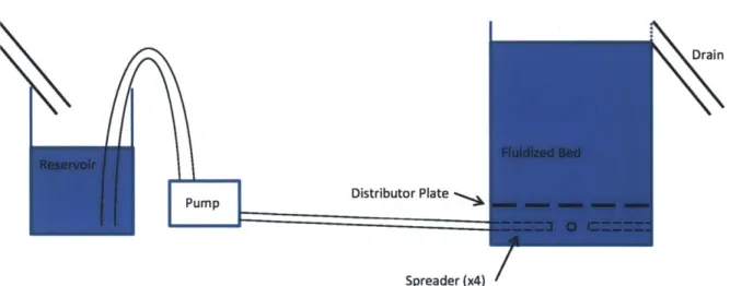
Water begins in a collector tank which prevents transients from affecting the system and allows for a smooth startup and shutdown of the pump system. It then flows into the water pump, which creates the necessary pressure and flow rate to fluidize the beads. Four tubes go from the pump to the four spreaders arranged at the base at 90 degree angles from each other. These spreaders have holes which create even pressure under the distributor plate. The distributor plate then creates a uniform upward flow of water. When the water reaches the top of the drum, it drains out
the side of the drum into the collector tank. See Fig. 2-1 for more details on system layout.
Drain
Distributor Plate
Spreader (x4)
/
Figure 2-1: This figure shows the layout of the full fluidized system. Water flows from
left to right across the system in a continuous loop.
2.4
Analysis
2.4.1
Volume Change and Packing Fraction
Calculating the volume change of the glass beads upon fluidization is essential for determining drum size. Assuming a height of 32 inches filled with beads (leaving space for bead expansion and a drain on top and distributor plate at the bottom), the volume of beads that can be used which will become fluidized is calculated based on change in packing fraction (the ratio of beads to total volume).
The first key aspect was determining the packing fraction of the beads at rest, which was measured from the current digging tank. Based on volume measurements, the packing fraction was determined to be 0.592, or a void fraction of 0.408. Since a void fraction of 0.45 is desired for fluidization, the change in volume of the beads can
be calculated as
AH = f - (2.1)
Adrum
where AH is the change in height, V5 is the volume when the beads are fluidized, V is the volume of the beads when they are at rest (packed), and Adrum is the area of the drum.
For a cylindrical space 26 inches in diameter and 32 inches tall, the change in volume from an increase in void fraction during fluidization results in a height change of less than 1.5 inches. This means a small space should be left at the top for the beads to expand, but the change in height is not significant.
2.4.2
Fluidization Flow Rate
In order to size the pump necessary for fluidization, the flow rate for fluidization must be calculated. Using this, the total volumetric flow rate of water can be calculated based on the cross sectional area of the drum. The theory for this section comes from Winter's Ph.D. thesis [2].
An empirical relationship between settling velocity v, and terminal velocity vt can
be developed, and depends on void fraction
4
of particles to the n as seen in Eq. 2.2.vS = vt$"n (2.2)
The correlation between Archimedes number (Ar) and the exponent n in the void fraction is given by
4.8
- =0.043Aro
.(2.3)
n - 2.4
with Ar defined as,
gd p5(p- 5
Ar = 2P(PP 2-
Pi)
(2.4)-5f
density, pp is the particle density, and p5 is the fluid viscosity.
The terminal velocity of the particle vt can be found in terms of Reynolds number
(Re) with
vt = Repl-pf (2.5)
where the Reynolds number of a sphere at terminal velocity can be modeled based on empirical data with the correlation in Eq. 2.6
Rept = [-3.809 + (3.8092 + 1.832Aro5)05 . (2.6)
Using Eqs. 2.2-2.6 gives the required velocity to obtain a desired void fraction. Thus, the fluid velocity required to achieve < = 0.45 for 20 mesh soda lime glass beads (0.841 mm in diameter) is 1.419. For a drum with a 26 inch diameter, this means a flow rate of 77 = or about 4600 min hourTga. This flow rate is experimentally derived,
and thus is the correct magnitude of order for the required flow rate. Further tests are necessary to determine the exact flow rate required for this case. The benchtop fluidized bed (discussed in Section 3.2) was built to determine the exact flow rate required for fluidization in this system.
As a note, upon measuring many of the glass beads, the average size is 0.65 mm. In order to fluidize beads this size, a flow rate of 1.012 is needed. Flow rate is highly dependent on bead diameter, and since the beads have a range of sizes, the necessary flow rate may vary accordingly.
2.4.3
Pressure Drop
Another important aspect of modeling the system was determining the pressure drops associated with each feature, to make sure the pump would be capable of delivering the necessary flow rate at a high enough pressure to overcome the losses of the system. The fluid flow through the system is shown as a resistor network in Fig. 2-2. For these calculations, a flow rate of 77- 4l is used. Pressure drop depends on flow rate, thusmsn
pump will help account for these changes to achieve the exact flow rate required by varying the pressure drop across the valve.
RPipes
Raistributor
Rbeass
Psupply
Figure 2-2: The flow through the system can be modeled as a circuit, with fluid flow as current, and fluid resistances comparable to electronic resistances. The resistance through the distributor is the resistance through the spreaders and the distributor plate. There are unique pressures at each point. The pressure at the bottom of the drum must be great enough to support the weight of the beads in a fluidized state. Note that Ohm's law does not hold for this system due to inertial effects of the water, but this schematic is an illustration that helps with calculating pressure at each location.
Using a balance of forces in the vertical direction, the pressure at the bottom of the drum can be calculated. This pressure is necessary to keep the beads in a fluidized state. Since the pressure at the top of the drum is atmospheric pressure, the pressure drop across the beads is equal to the pressure difference between the top and bottom of the drum. The gauge pressure at the bottom of the drum can be modeled
by Eq. 2.7
= [(1 - $)pbVdrum +
4pwVrum]
(2.7)Abottom
where g is gravity (9.84T),
#
is the void fraction (0.45), Pb is the density of the beads (2.52k), p1, is the density of water (1k), Vrum is the volume of the drum (0.256m3), and Abottom is the area of the drum floor (0.292m2). Solving the equation for this system yields a pressure drop of 1.58 x 10' Pa or 2.3 psi.There are also major and minor losses associated with the pipes and fittings in the system. Major losses are modeled by Eq. 2.8. The inlet and outlet pipes of the pump, as well as the manifold to split into four pipes are modeled.
AP=
fL
(1pV2) (2.8)where
f
= d is the friction factor of the pipe (0.00184), L is the length of the pipe(20 and 10 feet (inlet and outlet)), D is the diameter (1.5 and 1 inch), p is the density of water, and V is the velocity of water through the pipe (4.25 and 2.39 M).
Minor losses through valves and fittings are modeled by
AP = Kloss
(pv2
(2.9)where K10 8s is the loss coefficient for a certain geometry, which can be looked up in a
table [6].
By summing the major and minor losses from the pump though the hoses and fittings to the inside of the spreaders, a total pressure drop of 8.02 psi results.
Losses associated with the PVC spreaders and wire mesh can be modeled using the Bernoulli equation. Since height in the system remains approximately constant, this term cancels. This results in Eq. 2.10 [6]
AP = 2(V-V1
(2.10)
The design goal for the PVC spreaders was to have a pressure drop across the spreader. This leads to a more even flow out of the spreader, and evenly distributes water to all areas under the distributor plate. For this even flow to occur, a small pressure drop must occur across each spreader. By modeling the losses with the Bernoulli equation, the number and size of these holes can be determined. For the
whole system, one hundred 11/ 6 4 h inch holes must be drilled into the spreaders to
achieve a 0.35 psi pressure drop across the spreaders. This results in slightly more than one hole per inch on each side of the spreader. Since there will be some loss associated with the holes in addition to that predicted by the Bernoulli equation, this size was selected causing a small but measurable pressure drop to result, aiding in the even spreading of water.
There are one hundred eighty-eight holes that are each 1 inch in diameter, the total area that water can flow through is very large. Since the water is moving very slowly in the drum due to its large diameter, the pressure drop associated with the mesh and series of one inch holes is negligible.
Summing all of the losses in the system shows that an expected 10.7 psi pressure drop will occur from the pump to the surface of the fluidized bed. The AMT pump can produce the necessary flow rate with losses up to 10 psi, this pressure drop should suffice in evenly spreading out the flow of water while maintaining the needed flow rate for fluidization [1]. Fig. 2-3 shows the curve for the pump that was selected.
Figure 2-3: This figure shows the curve (E) for the flow rate versus pressure for the 1.5 HP AMT pump that was selected [1].
2.4.4
Exit Pipe Flow Rate
The exit size of the pipe is also an important aspect of the fluidized bed system. As pipe diameter increases, the height available for digging decreases. A small diameter pipe leads to the system overflowing, possibly damaging the robot or flooding the lab. In order to calculate the necessary size, iteration on Colebrook's equation which
1-1/2"x 1-112" MODELS
146 :=21in 2NPSP 3WTWC
E=2k3nia 1.1ZWIP 2UPTffC 126 F=WSleiws 39HPOOP 11PT&C G=M2Sais 1eHPQDP 349PTEFC
10
E
20 Operating Point
* 20 46 6 0 8 100 120 140 163 Capacity In US Gallons Per Minute @3460 RPM
relates the friction factor to the Reynolds number is necessary [6]. This equation is the basis for the Moody chart, but can be solved numerically using
1 -2.0 log + 2.51 (2.11)
f1/2
3.7 Redf/2
)where friction factor
f
=h,
with L as the pipe length (0.3 m), d is pipe diameter which we are solving for, h is the change in height (0.2 m), V is the flow velocity, and g is gravity (9.81 ), and c is pipe roughness (5 x 10⁻⁵ m). Re = Pvd, whereVd =
Q
= 0.00485!3, and t = 8.9 x 10⁴ NTo solve this equation it is necessary to guess the friction factor (starting with
0.03), calculate the diameter and Reynolds number, and use these to calculate a new
friction factor. This process is repeated until the answer converges. The converged answer is the minimum diameter necessary to remove a certain volumetric flow rate. In this case, the diameter needed is 2.1 inches. Since there is a mesh over the pipe which will restrict the flow, a slightly larger pipe should be selected. This should allow the water to exit through the screen at a high enough rate to prevent the drum from overflowing. Using too large of a pipe will limit the depth available for RoboClam to dig, since larger pipes have a larger diameter, meaning the water level in the drum will be lower. For a factor of safety but to maximize available depth for digging, a 3 inch diameter pipe will be used to remove the water from the top of the drum.
2.4.5
Plate Bending
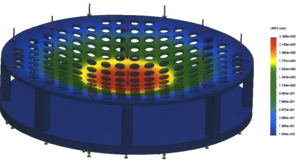
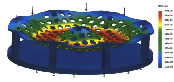
In order to size the plate that will be required to support the mass of the beads, the volume of the beads to fill the drum must be calculated. The mass of this volume of beads is about 900 pounds, or 4000 newtons. From this mass, a SolidWorks finite element analysis on bending forces in the plate can be run to determine the plate thickness necessary to prevent failure. A 1/4 inch plate of 6061 T6 aluminum was selected for the distributor plate. Fig. 2-4 shows plate bending with no support in the middle, and Fig. 2-5 shows bending with a 1.5 inch round support in the middle of the plate. Both cases have a factor of safety of three on the yield stress of the
material. LNES (mm) 2. 388e+000 I2,189e+0001.990&+(XM .791e+000 1 5921+00
A
1.393e+000 1.194e+000 9.950e-01 79W10S-(1 5S70e-1 3.980e-01 1.99oe-001 1 0000-M3Figure 2-4: This figure shows the bending of the 1/4 inch plate with a 4000 newton load applied. The displacement in this case is about 2.4 mm which is not large, but not insignificant.
2.4.6
Wire Mesh Strength
It was determined that the weight of the beads on top of the mesh would not be an issue for the design. Taking a vertical column of solid glass above the round holes in the distributor plate yields a volume of approximately 450 cubic centimeters of glass beads, which would weigh about 2.5 pounds. There are two factors which lessen the load over each of these holes. The beads are in water, so it is the buoyant mass of the beads which apply force to the screen. Buoyancy lessens their effective density
from 2.52'" to 1.52Eg, reducing the weight over each hole. The second factor
is the packing fraction of the beads. The beads are not a solid column of glass, but are packed closer to a 60% packing fraction, so the actual weight would be about 60% of 2.5 pounds acting over each hole, thus material selection is not as critical for supporting this weight. Since the mesh is made from 316 stainless steel, it is very
URES (-u) 1 3A71411 3.1810-01 2h92-01 .Z26036401
12
314e-0O1 1.157.6001 8.677-002 5.784-002 2 892e-2 1 D00-030Figure 2-5: This figure shows the bending of the 1/4 inch plate with a support added in the middle. In this case the maximum displacement iss only about 0.35 mm. strong and will not tear from the weight of the beads. The most difficult challenge is holding the mesh in place so it does not move due to the weight of the beads or from the upward flow of water during fluidization.
Chapter 3
Design Implementation
3.1
Overall Design For Manufacturing
Considera-tions
The system was designed to allow for easy assembly in house, with as few custom components as possible. Pipe fittings and hoses were selected to create four inlets in the drum with an even flow from each. The only custom component which requires any special tools, other than a welder or hand tools, is the distributor plate which is manufactured on a waterjet. Pipe fittings are inserted through the wall of the drum and welded with flanges to prevent leakage and ease the welding process. The distributor plate rests on brackets which were welded to the inside walls of the drum.
3.2
Benchtop Fluidization System
A miniature fluidized bed system was developed to validate the fluidized bed design.
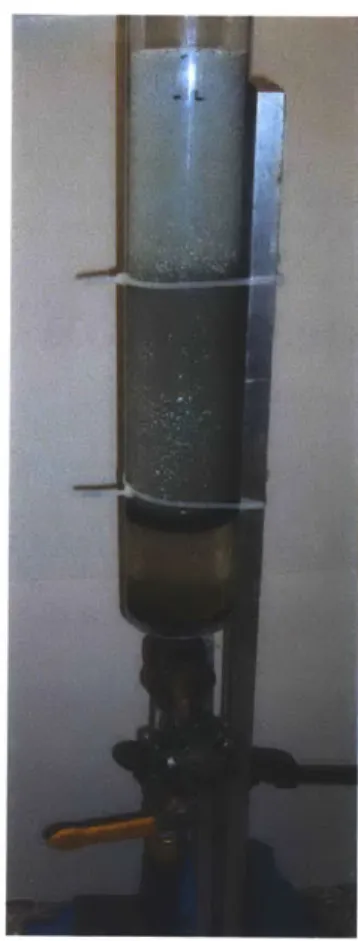
This system is necessary since acquiring very high flow rates is difficult due to higher than expected losses in the system. The goal of the system was to verify that the lower than desired flow rate would still result in sufficient fluidization in the large fluidized bed. The benchtop fluidized bed uses a 3.26 inch ID clear pipe, with a pipe fitting and mesh at the bottom. The benchtop setup allows for viewing of the beads
during fluidization and calculation of packing fraction versus velocity. Fig. 3-3 shows the benchtop fluidized bed system.
Figure 3-1: This figure shows the benchtop fluidized bed that was used to determine the flow rate needed for fluidization. The tube from the pump can be seen entering the bottom of the system. Water flows upward through the valve used to control flow rate, then into the clear visualizer section. Glass beads rest on the wire mesh, mounted between two pieces of black plastic. The system is mounted to an aluminum bar to hold the system upright, seen running up the right side of the visualizer.
3.2.1
System Layout
One of the four hoses from the pump is routed to the bottom of the benchtop fluidized bed. A valve at the end of the hose controls the flow rate into the small fluidized bed. One hole in the bottom of the large drum is plugged. This layout allows the large fluidized bed system to run as normal, while using small amounts of water for
the benchtop system. The reason for developing this layout was to allow the pump to run at near full capacity, putting less strain on the rather large pump. While the miniature fluidized bed is tested, water flows through the larger fluidized bed from the three other hoses. The valve on the benchtop version can be turned on slowly to allow small amounts of water into the system.
With this system, two key aspects can be measured. The upward velocity of water through the clear tube gives flow rate through the fluidized bed. By measuring the change in height of the beads in the tube, change in packing fraction can be calculated. Since no spreader system exists, water can be seen circulating in the system. The water travels up faster on one side than the other, and the beads have a tendency to move downward on the opposite side. Though they become unpacked and redistributed, the necessity of the spreader system can be observed. This first order model of the fluidization system allows for measuring of necessary flow rate to achieve the desired packing fraction. Any second order effects observed in the small system are of less concern.
3.2.2
Flow Rate Determination
In order to determine the necessary flow rate, the change in height of the beads must be calculated. To determine the initial packing fraction of the beads, the weight and height of the beads at rest is measured. Next, the height change needed to give a void fraction of 0.45 can be calculated. By measuring the upward velocity of the water when this change in bead height results, the flow rate can be calculated based on the cross sectional area of the benchtop setup.
The flow rate through the fluidized bed was set to match the flow rate that can be achieved through the larger drum. Marks were made on the column, and the valve was opened until the rate of 0.80' was reached, which corresponds with the measured flow rate through the drum. With this flow rate, the beads expand from
13 inches high in the column, to 14.5 inches. Thus, a void fraction of 0.52 can be
achieved with this flow rate. Even though the flow rate is lower than desired based on empirical measurements of necessary flow rate from Eqs. 2.2-2.6, the flow rate the
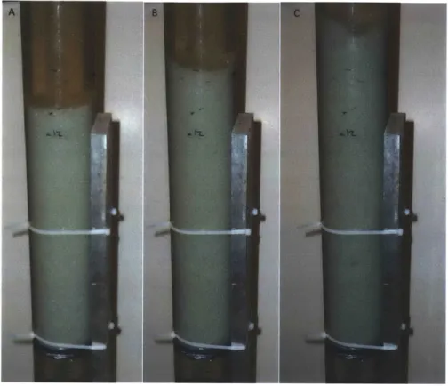
system achieves is sufficient to fluidize the beads to a void fraction of greater than 0.45. Fig. 3-2 shows different states of fluidization which occur at different flow rates.
Figure 3-2: This figure shows various states of fluidization. A) shows the beads at rest, with the lowest void fraction. B) has a void fraction of near 0.51. C) has the highest flow rate, and an even higher void fraction. The turbulence in the water flow for the highest flow rate case can be seen by the uneven surface of the beads at the top of C.
3.3
Component Selection
3.3.1
Drum Selection
A 96 gallon drum was selected to serve as the basin for testing the RoboClam with the new fluidization system. Currently RoboClam digs in a 30 gallon drum. While this is acceptable for use with the vibrator, the fluidization system introduces several
new challenges.
The first is the height for the distributor plate. At the bottom, water must flow in underneath the distributor plate. Once it is in this area, the fluid must spread out uniformly before passing through the distributor plate. If the area under the distributor plate is too narrow, there will be inadequate space for the water to spread before reaching the distributor plate, resulting in nonuniform flow. Increased space allows the flow to obtain uniform pressure across the entire bottom surface of the distributor plate. A clean-out port was also added to the bottom to allow access below the distributor plate without removing all of the beads and the plate from the
drum. This port allows for cleaning and checking on stability of the distributor plate and mesh. The area at the bottom reduces the height available for RoboClam can
dig.
The second challenge is the drain at the top of the drum. This drain allows water to run out from the top of the drum into the collector tank. A mesh is placed over the opening which prevents beads from going into the collector tank. Since the water level will be below the bottom of the tube which removes water from the drum, the level of beads in the tank will be lower than the bottom section of this tube, which
also limits the height available for digging.
An added benefit of the larger drum is larger diameter. The increased diameter will reduce the effects the walls of the drum have on preventing the outward expansion of beads. Larger diameter makes the setup more similar to the ocean and its nearly infinite field of substrate in which to dig, making the setup have a larger size scale difference between the robot and the test tank. This leads to easier digging due to decreased wall effects. The only drawback is the necessity of a larger volume of beads, making the system larger, heavier, and more complex than the current tank.
3.3.2
Distributor Plate Design
The distributor plate was designed to serve two purposes. First, it helps to evenly distribute water during the fluidization phase. Second, it supports the weight of the beads when they are at rest. SolidWorks FEA was run to determine that a 1/4 inch
thick aluminum plate is sufficient to support the weight of the beads when the system is not fluidizing the beads. When the system is fluidizing, the weight of the beads and water is supported by the bottom of the drum, since a force balance reveals that water pressure is acting on both the top and bottom surfaces of the plate.
Figure 3-3: This figure shows distributor plate after it has been waterjetted.
3.3.3
Distributor Plate Mounting
The distributor plate is composed of three parts. The main plate supports weight and has relatively large holes which allow water flow. A wire mesh supports the weight of the beads over each hole, while allowing water to flow through the small openings in the mesh. A thin top plate prevents the mesh from moving during fluidization. Fig. 3-4 shows this design. The mesh is designed to support the weight over each 1 inch hole in the distributor plate. These holes allow water to travel in an upward direction. Since the beads are less than 1 mm in diameter, this secondary system is
necessary, as it would be impossible to drill small enough holes in the plate to prevent the beads from falling underneath the plate.
Figure 3-4: This figure shows the sandwich architecture of the distributor plate. The 1/4 inch aluminum support plate holds the weight of the system. Wire mesh rests on this supporting the beads. A hold down plate is added on top of the mesh to prevent
it from moving during pump operation
3.3.4
PVC Spreaders
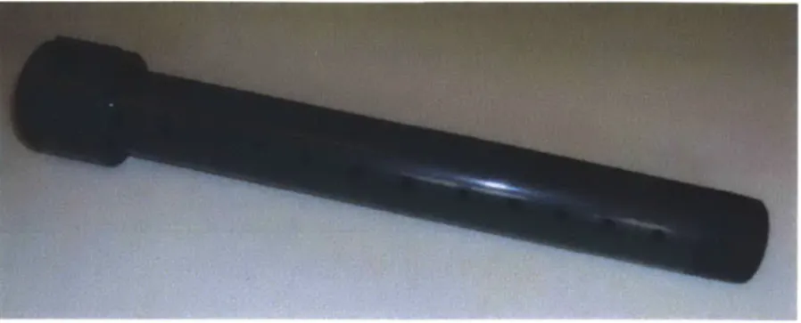
A PVC spreader system was also necessary to evenly distribute the flow of water underneath the distributor plate. This prevents high and low pressure areas which could have led to swirling and downward motion of water in low pressure areas. There are four distributors at 90 degree angles with respect to each other. Each has holes drilled in the PVC to let water out along its length. The pressure drop across these holes is overall slightly higher than the pressure drop in the pipes, allowing even distribution of the water as it exits these pipes, but not significantly reducing water flow. This creates a more uniform pressure distribution at the plate. Several concepts were considered to achieve even pressure distribution before this spreader design was selected. Fig. 3-5 shows the spreader design.
3.3.5
Hose and Fitting Selection
All hoses and fittings are standard 1 or 1.5 inch NPT fittings and hoses which can be screwed together with teflon tape. Three Ts bring the flow from one to four pipes which go into the drum in four locations through welded in fittings. This design methodology allows for all components to be commercially purchased and assembled, as simple four way splitters do not exist in the market.
Figure 3-5: This figure shows the PVC spreaders which cause a uniform pressure distribution in the bottom of the drum. Holes along the length let water out evenly across the bottom of the drum, creating an even pressure distribution.
3.3.6
Pump Selection
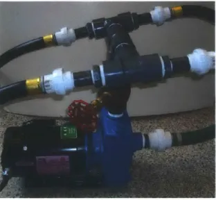
An AMT 6000 gallon per hour centrifugal pump was selected for the fluidized bed system (Fig. 2-3). The necessary flow rate is approximately 4600 gallons per hour based on empirical models, thus this pump can handle losses in the system of about 10 psi [1]. The total pressure loss through the hoses, spreaders, and beads is near 10 psi, so this pump was selected to circulate water in the system. Fig. 3-6 shows the pump with the manifold attached. The inlet is on the side, and the four outlet tubes can be seen exiting from the top.
Figure 3-6: This figure shows pump and manifold which brings water to the four PVC
spreaders inside the drum. Water flows into the pump on the left. A shutoff valve
allows for controlling the flow rate. Water then flows through the manifold to four
tubes leading to the drum.
Chapter 4
System Functionality
4.1
Testing the System
Tests were performed on the system in lab without spreaders or beads. A few changes were deemed necessary before the system can be completed and ready for integra-tion of the RoboClam. Fig. 4-1 shows the full system with the 96 gallon drum and connections in place.
4.1.1
Flow Rate
Testing the system by measuring time to fill a 5 gallon bucket at the drain port shows
that the flow rate is about 0.7 2 a. This flow rate was also derived by measuring the
change in height of the water level in the large drum when the pump is turned on. The vertical upward flow of water is 0.804. As was determined by the benchtop fluidization system, this flow rate is sufficient to reach a void fraction of greater than 0.45 as desired.
This flow rate is slower than expected for the pump that was selected based on the losses that were calculated. It seems as if the system is experiencing greater losses, which are likely due to all of the fittings before the water reaches the four hoses. If needed, there are a few things that can be done to increase the flow rate. The hoses could be made shorter, or the hoses leading to the drum could be larger in diameter.
Figure 4-1: This figure shows the fluidized bed system in its nearly completed state. Water flows out the top of the drum through the angled drain into the rectangular collector. From here it flows through the large tube into the pump. Four smaller black tubes enter in the bottom of the drum. The drum clean-out port can be seen
in front, which is also used for emptying the system.
These changes would reduce the major losses in the system. Smoother fittings could also be added, in addition to removing the valve on the output of the pump, which would reduce minor losses in the system, increasing flow. Further experiments are necessary with the PVC spreaders installed to determine if the flow rate in the large system is sufficient for fluidization.
4.1.2
Draining
Observing the draining of the system with the wire mesh in place shows that a larger drain is required. The mesh contributes to slowing the flow of water more than was
expected when selecting the size of the drain pipe. While the flow rate through the drain just matches the flow rate of the pump without the mesh in place, once beads are in the system and the mesh is added they will interfere with the flow of water, causing it to slow. A safety factor should also exist to prevent the system from overflowing. There are two options. Either a larger port can be added to the system to allow water to flow out, or a second exit location could be added.
4.1.3
Unpacking and Redistribution
While the flow pattern can be observed in the clear benchtop fluidized bed, it will be difficult to observe in the large fluidized bed. The small system reveals that swirling does occur, and that it is difficult to achieve even flow in all areas. Even with swirling, all of the beads become unpacked and move around in the small setup. This means it is likely that any soft spots in the large setup left by digging will disappear when the fluidized bed operates. The beads should also become more unpacked, and though it will not likely be a perfectly uniform flow over all areas, the beads will overall be unpacked and redistributed.
4.2
Future Work
This system was developed for use with RoboClam for burrowing, thus once the system successfully fluidizes, there is more work to be completed to make it to work with the robot. These steps will complete the project and allow for further testing of RoboClam in the lab.
4.2.1
Final Steps
The final steps involve making a larger drain port, integrating the spreaders and determining the proper hole size, and testing the system filled with beads. It is essential to ensure the system is ready to operate as intended, as once the beads are added, it is very difficult and time consuming to remove them. Therefore, once
the final flow rate is deemed sufficient to create fluidization, additional tests are necessary to determine if the flow rate with spreaders is still sufficient. Tests must also be performed to determine if the flow is even, which will allow for even fluidization across the entire drum.
4.2.2
Robot Integration
To finish integration with RoboClam, the robot will need to be mounted to the lid of the 96 gallon drum. The RoboClam software will be updated to allow for fluidization between each test. Once the fluidization pump runs and shuts off, the RoboClam will be able to dig in the unpacked and redistributed beads. Few changes are required as the RoboClam currently waits between each test while the beads are vibrated.
4.3
Implications for RoboClam
This new system will allow for accurate testing of the RoboClam in the lab. The vibrator test bed was a substantial improvement over transporting RoboClam to the ocean each time testing was desired. There were some issues with this first system that was developed, and with the new fluidized bed, many of these issues have been addressed. The new test setup will better simulate ocean substrate and allow for continued development of RoboClam as a burrowing device to be used for underwater vehicles or other applications. It will also be useful in the future for developing other ocean floor related technologies.
Bibliography
[1] AMT. Amt pump specifications. http://amtpump.com/products/c55-56.shtml.
[21 Amos G. Winter, V. Biogically inspired mechanisms for burrowing in undersea substrates. Massachusetts Institute of Technology, Mechanical Engineering PhD
Thesis, 2011.
[31 E.R. Trueman. Bivalve mollusks: Fluid dynamics of burrowing. Science,
152(3721):523-525, 1966.
[4] E.R. Trueman. The dynamics of burrowing in ensis (bivalvia). volume 166 of B,
Biological Sciences, pages 459-476, 1967.
[5] Mario A. Bollini. The design of scaled robotic end effectors to mimic razor clam
burrowing. Massachusetts Institute of Technology, Mechanical Engineering SB
Thesis, 2009.

![Figure 2-3: This figure shows the curve (E) for the flow rate versus pressure for the 1.5 HP AMT pump that was selected [1].](https://thumb-eu.123doks.com/thumbv2/123doknet/14684210.559887/24.918.275.635.444.740/figure-figure-shows-curve-flow-versus-pressure-selected.webp)