MITLibraries
Document Services
Room 14-0551 77 Massachusetts Avenue Cambridge, MA 02139 Ph: 617.253.5668 Fax: 617.253.1690 Email: docs@mit.edu http://libraries.mit.edu/docsDISCLAIMER OF QUALITY
Due to the condition of the original material, there are unavoidable
flaws in this reproduction. We have made every effort possible to
provide you with the best copy available. If you are dissatisfied with
this product and find it unusable, please contact Document Services as
soon as possible.
Thank you.
Some pages in the original document contain pictures,
graphics, or text that is illegible.
SCHERING-PLOUGH LIBRARY
DESIGN AND DEVELOPMENT
OF A MULTIFIBER SHIELDED LASER CATHETER SYSTEM FOR REMOVAL OF ATHEROSCLEROTIC PLAQUE
by
Robert M. Cothren, Jr.
S.B., Massachusetts Institute of
(1981)
M.S., Massachusetts Institute of
(1984)
Technology
Technology
Submitted in Partial Fulfillment
of the Requirements of the
Degree of
Doctor of Philosophy
in Medical Engineering
at the
Massachusetts Institute of Technology
June, 1987
(c) Copyright Robert M. Cothren, Jr., 1987
The author hereby grants to MIT permission to reproduce and to
distribute copies of this thesis document in whole or in part.
Signature of Author
Certified b]
Accepted by
Co-Directcd;
DjCsion of
eatVh
Sciences
'd)Technology
June,
1987
\ -
Michael S. Feld
fA
Thesis Supervisor
(I
'
Roger G. Mark
DESIGN AND DEVELOPMENT
OF A MULTIFIBER SHIELDED LASER CATHETER SYSTEM
FOR REMOVAL OF ATHEROSCLEROTIC PLAQUE
by
Robert M. Cothren, Jr.
Submitted to
the Division of Health Sciences and Technology in June, 1987,
in partial fulfillment of the requirements of the Degree of Doctor of Philosophy
in Medical Engineering
ABSTRACT
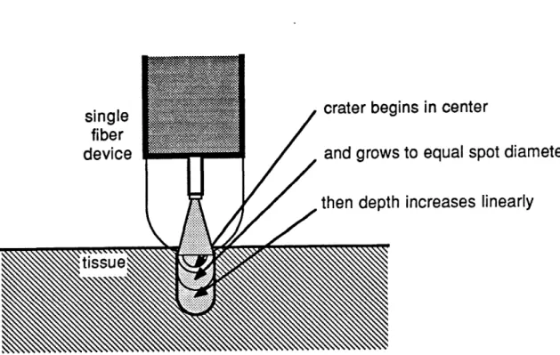
A multifiber laser angiosurgery system was developed which is capable of controlled laser ablation of arterial ob-structions in vivo. Development of the system can be broken down into a few important steps.
A laser light delivery scheme employing an optical fiber enclosed in a transparent optical shield was developed to al-low for the controlled delivery of laser energy. Characterization of this delivery scheme using argon ion laser light showed that quantitatively predictable tissue ablation could be achieved. Ablation proceeded at a constant rate, with the depth of the ablated crater increasing linearly with time. The crater diameter approached the incident laser spot diameter for sufficiently long exposure times. The ablation
process was also shown to be additive if multiple exposures were used, that is, each successive exposure produced an in-crease in the crater depth equal to the exposure preceeding it.
This delivery scheme was then extended to a multifiber shielded laser angiosurgery catheter system, which was designed to be capable of controlled laser ablation of arterial obstructions. That system consisted of a multifiber shielded catheter employing the controlled delivery scheme of the transparent optical shield, an optical system which al-lowed for remote location of the laser source and careful shaping of the catheter's output beam profile, and a sophisticated computer based control system to operate and monitor the ablation process.
Characterization of that system demonstrated that, as be-fore, ablation proceeds at a constant rate, with the depth of the ablated composite hole increasing linearly with time, and, as before, the ablation process was additive if multiple expo-sures are used. An ablation yield, the volume of tissue removed per unit of energy delivered, wag defined, and found to be constant at a value of 0.16mm /J for many different laser exposure parameter combinations. A threshold laser power of 1W was identified, a minimum power required to over-come the loss of energy through thermal diffusion. A thres-hold exposure time of 10ms was also identified, corresponding to a minimum energy that must be delivered to raise the tissue's temperature to the ablation temperature and deposit the latent heat of ablation. Histological evaluation of the peripheral damage imposed by laser ablation showed that a layer of 100-200um of vacuolization and hypereosinophilia sur-rounded each composite hole, a level of damage that should be acceptable.
The successful use of the laser angiosurgery system using the multifiber shielded catheter was also demonstrated in an animal model. Both controlled recanalization of the ob-structed artery and evidence of proper healing of the treated site were shown.
A simple theoretical model for laser ablation is also presented which describes the way in which different laser and tissue parameters effect the ablation process. The ablation velocity and ablation efficiency predicted by this model were
in good experiments.
agreement
with results of multifiber deviceThesis Advisor: Michael S. Feld Professor of Physics
ACKNOWLEDGEMENTS
To Professor Michael Feld, advisor and friend, whose sup-port and guidance were instrumental in the successful comple-tion of this work. Throughout my graduate career, he both taught me as a student and listened to me as colleague.
To Dr. John Kramer, cardiologist at the Cleveland Clinic Foundation, whose advise constantly help direct both this work in particular and the Laser Angiosurgery Project in general.
To Carter Kittrell, who was always willing and anxious to assist when things were not working and explain the sometimes puzzling operations of modern optics and detection systems.
To pathologist Dr. Burr Ratliff and surgeons Dr. Floyd Loop and Dr. Bruce Lytle of the Cleveland Clinic Foundation, whose professional advice was freely given and always welcome. To Gary Hayes, who has, without complaint, been ever wil-ling to build any and every permutation of catheter I could dream up. Without his steady hand, open mind, and desire for perfection, this project would not be where it is today.
To all of the students and colleagues of the MIT Laser Angiosurgery Group, who over the years have made the MIT Spec-troscopy Lab an interesting and fun place to be. They provided a constant source of minds with which to share ideas and discuss problems, and friends with which to share good times.
To Carol, Kim, and Sue, who were willing to put up with the constant presence of a graduate student keeping them from thier work with conversation and administrative details.
To my parents, who have supported me throughout my schooling. It was their guidance,-support, and love that have kept me going through my entire life at school.
But most importantly, to my wife Daphne, who saw me through many hard times, long days, and sleepless nights. Her patience and love, her understanding and willingness to sacrifice, have made it possible to complete my career at MIT with some spirit, joy, and sanity.
This work was part of an ongoing Laser Angiosurgery Pro-ject, a collaboration between the MIT Spectroscopy Laboratory, the Cleveland Clinic Foundation, and American Hospital Supply Corporation.
TABLE OF CONTENTS
SECTION I INTRODUCTION . . . . I.1 Atherosclerotic Disease
1.2 Treatment Modalities for Atherosclerotic Disease . . . . 1.2.1 Arterial Bypass Surgery . . . . 1.2.2 Balloon Angioplasty . . . . 1.3 Laser Angioplasty . . . . 1.4 Current Approaches to Laser Angioplasty I.4.1 Laser Systems . . . .
1.4.2 Laser Delivery Techniques
1.5 Laser Angiosurgery . . . . . 1.6 Purpose . . . . References . . . .
SECTION II CONTROLLED DELIVERY OF LASER ENERGY . II.1 Overview
II.2 Control of Optical Parameters: The Optical Shield . . . .
II.3 Other Advantages of the Transparent Optical Shield . . . .
II.4 Selection of a Laser System . .
References . . . .
SECTION III SINGLE FIBER SHIELDED DEVICE BEHAVIOR III.1 Overview . . . . III.2 Experimental Methods . . . . III.3 Results . . . . III.3.1 Variation in Ablation Rate with
Varying Power . . . . III.3.2 Variation in Ablation Rate with
Varying Spot Diameters . . . . . III.3.3 Variation in Ablation Rate with
Repeated Exposures . . . . III.4 Discussion . . . . . 6 7 8 9 10 10 15 20 20 22 26 26 26 31 32 34 . . . 35 *. . 35 . . . . 36 . . .: . 40 41 44 47 50 . . . * . . . . . . . . . . . . . . . . . . . . .
References . . .. . .. . . .
SECTION IV LASER/TISSUE INTERACTION . . . . IV.1 Overview . . ... . . . IV.2 Review of Ablation Models . . . . IV.3 Principles of the Pseudo-Steady State
Approach . . . . IV.4 Theoretical Model . . . . IV.5 Discussion .. . . . . References . . . .
SECTION V MULTIFIBER LASER ANGIOSURGERY SYSTEM DESIGN V.1 Overview . . . .
V.2 Multifiber Shielded Catheter Design
Concepts . . . . V.3 Description of the Multifiber Catheter V.4 The Laser Angiosurgery System . . . . . V.4.1 Optical Subsystem . . . . V.4.2 Control Subsystem . . . . References . . . .
SECTION VI MULTIFIBER SHIELDED CATHETER BEHAVIOR VI.1 Overview . . . . VI.2 Experimental Methods . . . . VI.3 Results . . ...
VI.3.1 Variation in Ablation Rate with Varying Power . . . . VI.3.2 Variation in Ablation Rate with
Repeated Exposures . . . . VI.3.3 Selective Removal of Tissue with a
Multifiber Catheter . . . . VI.4 Discussion . . . .
SECTION VII MULTIFIBER CATHETER ABLATION EFFICIENCY VII.1 Overview . . . . VII.2 Experimental Methods . . . . VII.3 Results . . . . VII.3.1 Variation in Ablation Yield in
Different Tissue Samples . . . . . VII.3.2 Variation in Ablation Yield and
Damage with Varying Power . . . . VII.3.3 Variation in Ablation Yield and
Damage with Varying Exposure Time VII.3.4 Variation in Ablation Yield with
Varying Advancing Force . . . . . VII.3.5 Variation in Ablation Yield and
. 116 . . . 116 . . . 117 . . . 118 . . . 119 . . . 121 . . . 124 . . . 126 56 57 57 58 61 65 75 85 88 . . 88 88 91 95 95 97 104 ... . 105 .... 105 ... . 105 . . 107 . . . . 107 .... 111 . . . . 113 . . . . 114 * @
Damage with Varying Delay Times VII.3.6 Variation in Ablation Yield with
Catheter Usage . . . . VII.4 Discussion . . . . References . . . .
SECTION VIII LASER ANGIOSURGERY IN AN ANIMAL MODEL VIII.1 Overview . . . . VIII.2 The Animal Model . . . .... VIII.3 Experimental Procedure . . . . VIII.4 Results . . . . VIII.5 Discussion . . . . References . . . ...
SECTION IX CONCLUSION ...
IX.1 Conclusions from this Study ...
* . . 128 . . 130 * . . 132 . . 141 142 142 143 146 147 149 152 * . . 153 . . . 153 · · · · · · · · · · · · · · · · · · · · ·
LIST OF FIGURES
Schematic of the Pathogenesis of Atheroslcerosis . . ... 3
Components of Atherosclerotic Plaque . . . 4
Histological Sections of Coronary Atherosclerotic Plaque . 5 Natural History of Atherosclerosis . . . 6
Current Laser Angioplasty Delivery Schemes ... 19
Shortcomings of Bare Fiber Laser Light Delivery ... 28
Shielded Fiber Laser Light Delivery . . . 30
Single Fiber Shielded Device . . . ... 37
Single Fiber Shielded Device Output Profile ... 38
Visualization of the Single Fiber Shielded Device Output 39 Typical Single Fiber Crater Histology at 750um Spot Diameter . . . .. . . .. 42
Single Fiber Crater Diameter Versus Laser Power . . . . 43
Single Fiber Crater Depth Versus Laser Power ... 44
Single Fiber Crater Diameter Versus Spot Diameter . . . . 46
Single Fiber Crater Depth Versus Spot Diameter ... 47
Typical Single Fiber Crater Histology at 500um and 10W . 49 Single Fiber Crater Depth Versus Number of Exposures . . 50
Time History of Crater Formation . . . ... 54
Schematic Diagram of the Ablation Process . . . ... 63
Schematic of Multifiber Catheter Shield . . . .. 92
Schematic of Multifiber Catheter Fiber Orientation . . . 93
Light Spot Pattern of 8F Multifiber Catheter . . . . .. 94
Schematic of the Laser Angiosurgery Optical Path . . .. 96
Reticon Map of a Multifiber Catheter Intesity Profile .. 97
Schematic of the Laser Angiosurgery Control Subsystem .. 98
Schematic of the Full Laser Angiosurgery System . . . .. 102
WILBUR Control Program Screens . . . 103
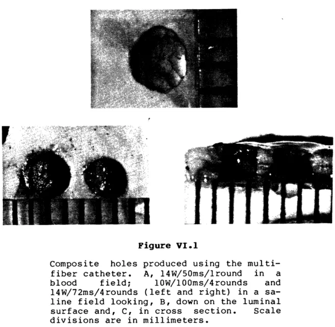
Typical Composite Holes Grossly . . . 109
Multifiber Composite Hole Depth for Varying Laser Power . 110 Single-fiber Crater Depth for with Multiple Exposures . 112 Selective Tissue Removal with a Multifiber Catheter . . . 114
Typical Multifiber Composite Hole Histology (a) ... 122
Typical Multifiber Composite Hole Histology (b) ... 123
Multifiber Ablation Yield Versus Exposure Time . . . 126 Multifiber Ablation Yield Versus Advancing Force . . . . 127 Multifiber Ablation Yield Versus Delay Time ... 129 Multifiber Peripheral Damage Versus Delay Time . . . 130 Multifiber Ablation Yield Versus Number of Exposures . . 132 Induction of Lesions in a Dog Model . . . 145
Angiogram of the Model Obstruction . . . 146
Post-treatment Angiogram of the Model Lesion . . . 148 Two Week Post-treatment Angiogram of the Model Lesion . . 149
LIST OF TABLES
Laser Systems for Ablation of Atheromas . . . 14
Single Fiber Threshold Times and Ablation Velocities . . 52
Physical Constants for Tissue . . . 76
Single Fiber Ablation Velocities . . . 78
Experimental f(d) Values . . . 79
Observed and Predicted Ablation Velocities . . . 80
Multifiber Ablation Velocities for Varying Power . . . . 111
Multifiber Incremental Advancement . . . .. 113
SECTION I INTRODUCTION
1.1 ATHEROSCLEROTIC DISEASE
Arteriosclerosis is the name given to a group of diseases
generally characterized by a thickening of the arterial wall
and a loss of the wall's elasticity [1].
Of the three major
forms of arteriosclerosis, the most common is
atherosclerosis
[1,2].
Atherosclerosis
is
a degenerative disease of the
large-and medium-sized arteries in
which atheromas
containing
cholesterol, lipoid and fibrous material, cellular debris, and
calcium are formed within the intima and inner media
[1].
A
number of risk factors such as hypercholesterolemia,
hyperten-sion, smoking, diabetes, obesity, age, and
lack of
physical
activity
have
been
correlated with the development of
atheromatous plaque, though a cause
and effect relationship
INTRODUCTION ATHEROSCLEROTIC DISEASE
Although the pathogenesis of atherosclerosis has been the
subject of intense investigation for many years, the exact
steps leading to the formation of atheromatous lesions is
still not clear. It is generally thought to be a complex
com-bination of two mechanisms: intimal injury and increased
up-take of lipid by the artery wall. Figure I.1 diagrams
schematically the steps that may be involved as these two
mechanisms proceed. High concentrations of low density
lipoproteins (LDL) induce endothelial injury and the adherence
and aggregation of platelets; platelet aggregation is
prompted further by the injury itself. The endothelial
in-jury, along with hyperlipoproteinemia, leads to an increased
rate of LDL penetration into the subendothelial space. Both
the increased concentration of LDL in the arterial wall and
factors released by the platelets are probably responsible for
the stimulation of smooth muscle cell proliferation and the
entrapment of LDL in the extracellular fibrous matrix which
secreted by them. The continual reiteration of this process
eventually gives rise to a space filling atheroma made up of a
fibrous region of proliferated smooth muscle cells, collagen,
and lipoid material and, eventually, a necrotic center of
cel-lular debris, cholesterol crystals and cholesterol esters, and
INTRODUCTION ATHEROSCLEROTIC DISEASE I INCREASED LDL LEVELS PLATELET ADHERENCE AND AGGREGATION RELEASE OF PLATELET-OERIV GROWTH FACT(
+
ChAnnTU RhllCrlINCREASED O INCREASED RATE OF PERMEABILITY LOL PENETRATION TO
SUBENDOTHELIAL SPACE
Jb. INCREASED CELL UPTAKE OF LDOL
CHOLESTEROL EFFLUX
~JIVluU InI IVlUJ .LL
CELL PROLIFERATION +
WITH SECRETION OF ACCUMULATION OF MATRIX ELEMENTS CHOLESTEROL ESTERS
ATHEROMA
FROM CELLS
Figure I.1
Schematic diagram of the probable interac-tions between the two major pathogenic mechanisms of atherogenesis [6].
The process of atheroma formation begins early in life with the appearance of fatty streaks in the intimal lining of the arteries. The disease does not become clinically signifi-cant however until at least 75% of the diameter of the vessel's original lumen has been filled by the developing
plaque. At this point, blood compromised.
flow becomes seriously The disease most commonly manifests itself as ischemic pain (i.e., angina or claudication) resulting from
O
ENOOTHELIAL Is III V "Illu' I FA(/.
IINTRODUCTION ATHEROSCLEROTIC DISEASE
DIAGRAM OF AN ATHEROSCLEROTIC PLAQUE
A -ADVENTITIA
RELATION OF PLAQUE COMPONENTS TO CLINICAL EFFECTS
... rcIBROUS CAP
Sf @· . CDIDEM ANGFRDO BECAUSE OF
*(, E5
~3~-~
· · IIE SIZE, TENDENCY TO FRACTURE AND ULCERATEY C-- g d .i9 U -SW 2 NECROTIC ·CORE
4, O mu, S IZE, CONS ISTENCY
axC1' E4AND THROMBOPLASTIC
O ~..\~~~~~ OX \~,~ : .4 z _ .SUBSTANCES e o \ o * o o e * o v * M @ / */o /\ e0 a e
0°1 / O * o / Ot e o~ 'o
o°. ' o o \o / .,a o°X o',, ;:e_
Figure 1.2
Major components of the advanced atheros-clerotic plaque [1].
inadequate delivery of oxygen, aneurysm formation due to
deterioration of the artery, and stroke, heart attack, or
in-farct of some other tissue due to complete interruption of
blood flow (see Figure 1.4) [1,10].
Nearly one million Americans die each year as a direct
result of cardiovascular disease, making it the cause of
al-most half of all deaths in this country. Nearly five million
INTRODUCTION
ATHEROSCLEROTIC DISEASE
. W .- ,. .- = w , .O . Z~~~~~ . .;*I . . : . .. ., ; . I I.* - .~' ., , . . - iFigure
I.3
Histological sections of advanced
atheros-clerotic plaques in the coronary arteries
of
two people.
Note the principal
com-ponents of fibrous cap and necrotic core
in each [1].
disease,
with another two million suffering from strokes, both
70- 60- 50-O, <40-Z 30-C, < 20- 10-The [1] . MYOCARDIAL INFARCT
- -1
I l %I Inatural
INTRODUCTION ATHEROSCLEROTIC DISEASECEREBRAL GANGRENE OF ABDOMINAL AORTIC INFARCT EXTREMITIES ANEURYSM
CLINICAL HORIZON CALCIFICATION COMPLICATED LESION-HEMORRHAGE, ULCERATION, THROMBOSIS FIBROUS PLAQUE a) FATTY STREAK
0
Figure I.4 history of atherosclerosis1.2 TREATMENT MODALITIES FOR ATHEROSCLEROTIC DISEASE
There are two major corrective treatments for occlusive
atherosclerotic lesions in popular use today: surgical bypass
and balloon angioplasty. Both of these modalities are
designed to restore full blood flow in the artery distal to
the obstructive lesion and return perfusion to the target
tis-sue. Although both modalities have enjoyed increasing success
over the last several years, each has some serious drawbacks.
INTRODUCTION TREATMENT MODALITIES FOR ATHEROSCLEROTIC DISEASE
I.2.1 Arterial Bypass Surgery
The specifics of the bypass technique vary with the
loca-tion and size of the diseased artery. In most cases, a
seg-ment of vein or artery from elsewhere in the patient's body is
grafted to the diseased artery around the site of stenosis to
provide an alternate path for blood flow. Over 200,000
coronary bypass operations are performed annually in the
United States alone [2]. Success of this technique is very
good, with a national operative mortality rate of only 2.3%.
Bypass grafts usually provide adequate flow for seven to ten
years without complication or obstruction of the graft [1].
When the graft does fail, usually due to plaque formation in
the graft, the procedure can often be repeated once.
However, like any surgical technique, arterial bypass has
disadvantages. The surgery is very traumatic to the patient.
It is expensive; coronary artery bypass usually costs $16,000
or more, with a required hospital stay of seven to ten days.
Not all patients are good candidates for bypass surgery. If
atheromas are located diffusely throughout the vessel, a
sig-nificant increase in blood flow may not be realized. Some
vessels may be too small to make bypass feasible [1]. Because
INTRODUCTION TREATMENT MODALITIES FOR ATHEROSCLEROTIC DISEASE
normally only be repeated once, bypass surgery is usually
reserved for older patients.
1.2.2 Balloon Angioplasty
A more recently developed alternative is percutaneous
transluminal balloon angioplasty. In this technique, a
catheter with a small balloon at its distal end is inserted in
a peripheral artery and advanced to the point of occlusion.
The balloon is placed across the lesion where it is inflated
with several atmospheres of pressure. The artery wall and
plaque are fractured and displaced, leaving an enlarged lumen.
Because only a small incision is made in the skin,
an-gioplasty is much less traumatic to the patient, less
expen-sive, and requires only a few days of hospitalization. It can
also be repeated as many times as is required, making it the
procedure of choice for young patients not responding to
medi-cal management. The procedure is relatively safe, requiring
emergency bypass surgery in about 6% of patients, and with a
national mortality rate of less than 1% [1].
However, balloon angioplasty can not be performed in all
situations. It is usually used only for single vessel disease
(approximately 80% of cases). It cannot be used if the
INTRODUCTION TREATMENT MODALITIES FOR ATHEROSCLEROTIC DISEASE
deflated balloon. It can seldom be used near a point of
bi-furcation where it might crush the branching vessel. Long or
diffuse lesions can be treated with only limited success.
Perhaps the biggest drawback of balloon angioplasty however is
the recurrence of stenosis. From 15% to 20% of lesions
treated by balloon angioplasty reocclude to a point requiring
repeat treatment within six months, and nearly 60% reocclude
within two years [1].
1.3 LASER ANGIOPLASTY
Removal of atheromatous obstructions by ablation using
laser energy (so called laser angioplasty) has received a
great deal of interest from researchers as an alternative to
bypass surgery and balloon angioplasty. Conceptually, laser
ablation of atheromas has advantages over both of these
techniques. Since optical fibers can be used to carry laser
energy to the lesion, percutaneous techniques can be employed
making the trauma and cost imposed by surgery unnecessary. It
is hoped that removing the obstructive lesion by ablation,
rather than merely displacing it with a balloon, will produce
a good clinical result without the high restenosis rate which
INTRODUCTION LASER ANGIOPLASTY
applicable as a treatment for long or diffuse lesions, and
lesions at arterial bifurcations.
Many researchers have demonstrated that many types of
tissue, including arterial tissue and atheromatous plaques,
can be ablated using laser light [11-13]. Further, Gerrity
studied the long term effects of laser ablation of
atheroma-tous tissue in a porcine model in which atherosclerotic
le-sions were produced by a combination of hypercholesterolemic
diet and balloon deendothelialization of the abdominal aorta.
Complete intimal healing with reendothelialization was found
within two weeks after laser ablation of lesions [14].
I.4 CURRENT APPROACHES TO LASER ANGIOPLASTY
Experimental use of lasers in the vascular system was
first reported in the early 1980's. Although research is
be-ing conducted at a large number of centers, laser delivery
systems designed for use in the vascular system have remained
relatively simple and unsophisticated.
I.4.1 Laser Systems
The wide variety of lasers being investigated for
INTRODUCTION CURRENT APPROACHES TO LASER ANGIOPLASTY
groups, continuous wave
(CW) lasers and pulsed lasers, and
subdivided by wavelength.
Continuous lasers are characterized by the delivery of up
to hundreds or even thousands of watts of
continuous power
over a broad range of the spectrum. The ablation mechanism of
these lasers is most likely to be thermal in
nature, brought
on
by
the
heating of
absorbing material in the tissue and
vaporization of the tissue's water. The rapid generation of
steam carries away
tissue components, which may be further
pyrolyzed by the incoming laser light. The
three continuous
lasers
attracting
the most attention are
neodimium:YAG
(Nd:YAG), carbon dioxide (CO
2), and argon ion.
Nd:YAG lasers have proven their usefulness in
photocoagu-lation therapy such as the treatment of ulcers of the stomach,
esophagus,
and colon, and have further been used in arterial
and nervous anastomosis
[15].
However,
the property that
makes this laser well suited for photocoagulation makes it
poorly suited for ablation. Nd:YAG radiation at
1.06um or
1.32um is
weakly absorbed by most biological tissues [16].
Large zones of moderate tissue heating are easily obtainable,
but heating may not be
intense enough for clean ablation.
INTRODUCTION CURRENT APPROACHES TO LASER ANGIOPLASTY
lasers are normally surrounded by large zones of thermal
necrosis [17].
The 10.6um radiation from CO2 lasers is strongly absorbed
by tissue water and thus penetrates only a few microns into
the tissue [18]. This property has made the CO2 laser a very
popular choice for surgical applications, where clean cuts and
rapid healing in many types of tissue, including
atheros-clerotic models in swine, have been demonstrated [14].
However, optical fibers which transmit 10.6um are not
commer-cially available, preventing the use of CO2 radiation
percu-taneously.
Argon lasers fill a middle ground between Nd:YAG and CO2.
The 488nm and 514nm radiation from the argon ion laser is
ab-sorbed in about 1/3mm of tissue [16], making it capable of
removing tissue without extensive thermal damage if the laser
intensity and exposure duration are carefully controlled. The
visible wavelengths of this laser are readily transmitted by
commercial optical fibers used in the communications industry.
However, argon ion laser radiation has proved ineffectual in
removing calcified plaque [19-21]. The use of the alternate
argon ion 356nm radiation may increase that laser's
suitabil-ity for tissue ablation because of the increased tissue
INTRODUCTION CURRENT APPROACHES TO LASER ANGIOPLASTY
Pulsed lasers are characterized by the delivery of short
bursts of light with very high peak power, typically in the
range of megawatts for a fraction of a microsecond. The
abla-tion mechanism of these lasers is not well understood, but
postulated mechanisms range from thermal to photochemical
pro-cesses, with or without the formation of plasmas. A number of
pulsed laser systems, including excimer, pulsed Nd:YAG, pulsed
dye, and, to a lesser extent, pulsed CO2 have been used to
create very clean craters in tissues of all types, including
calcified atherosclerotic plaque, kidney stones, and even bone
[19-21]. Recent studies have shown that erbium:YAG (Er:YAG)
and hydrogen fluoride (HF) lasers can produce similar results
[22,23]. However, the very high peak powers generated by all
of these lasers makes transmission through optical fibers
INTRODUCTION CURRENT APPROACHES TO LASER ANGIOPLASTY
laser wavelength type
tissue
absorber
excimer UV/pulsed UV/pulsed UV/pulsed UV/pulsedargon
193nm 248nm 308nm 351nm VIS/CW 488-514nm Nd:YAG VIS/pulsed IR/pulsed IR/CW CO2 IR/pulsed IR/CW 532nm 1064nm 1.06um 10.4um 10.4umprotein
protein
no
difficult
protein difficultprotein
difficult * yes * difficult * difficult *water
water
yes
future
future
Nd: YAGargon
pulsed dye
Er:YAG
HF UV/pulsed IR/CW 355nm 1.32um UV/CW 351-364nm pulsed IR/pulsed UV-IR 2.9um IR/pulsed 2.6-3.lum IR/CW 2.6-3.lum Table I.1protein
*protein
difficult yes yes * difficultwater
water
water
future
future
future
Lasers systems currently for ablation of atheromas.
being explored Wavelengths
range
from well
into the ultraviolet to
well in the infrared.
Probable tissue
ab-sorbers and the
availability of optical
fibers are noted.
* Tissue absorbs only weakly at these
wavelengths. The specific absorber in the
tissue is largely unknown.
laser
system
fiber optics
INTRODUCTION CURRENT APPROACHES TO LASER ANGIOPLASTY
1.4.2 Laser Delivery Techniques
A number of schemes have been proposed to deliver laser
energy to a lesion in the vascular system. The common use of
optical fibers to carry the laser radiation in all of these
schemes has largely limited laser ablation systems to
continu-ous visible or near infrared laser radiation. The argon ion
laser has largely been the laser of choice.
The earliest delivery systems consisted of a single
opti-cal fiber passed through the lumen of a catheter. Others also
incorporated a coherent fiber bundle for visualization of the
arterial lesion during ablation.
The first successful attempt to recanalize occluded
peri-pheral arteries was performed in 1982 using a device of this
type [24]. An argon ion laser was used to treat a thrombus
produced in the ligated vessel of a dog. Histological
ex-amination showed that initial intimal necrosis was followed by
complete intimal healing after five days with no
post-treatment thrombus formation. Successful recanalization
of human atherosclerotic arteries, which were grafted into the
circulation of a dog, has also been demonstrated with a
similar device [25]. Nd:YAG lasers have been used to remove
model lesions produced in rabbits through the combined use of
INTRODUCTION CURRENT APPROACHES TO LASER ANGIOPLASTY
limited
success
[26-28].
Unfortunately,
results have been
plagued by complications due
to aneurysm
formation and/or
arterial perforation.
The first
reports of clinical use of laser ablation of
atheroma was
published in 1984,
again using this simple
delivery scheme
[29].
In five patients undergoing coronary
bypass surgery, an argon ion laser was
used to
recanalize
coronary stenoses of 80-90%.
Recanalization was initially
successful in three of the five cases.
Since
that
time,
a
number of researchers have reported successful recanalization
of femoral arteries and popliteal arteries, using the
argon
ion
laser or the Nd:YAG laser delivered through simple fiber
optic systems [30-33].
However, control of
the
laser light
was a consistent problem, and balloon angioplasty was often
used after laser treatment, greatly clouding the
results of
these studies.
In 1985,
a different type of delivery scheme was
intro-duced in which the optical fiber was capped with a metal tip
which absorbed all of the laser radiation. The laser was
sim-ply used to deliver power to heat this,
tip which
in
turn
heated the
tissue to "melt" or "vaporize" the tissue it
con-tacted.
INTRODUCTION CURRENT APPROACHES TO LASER ANGIOPLASTY
This technique has been shown to reduce stenotic model
lesions induced in rabbits by the use of hypercholesterolemia
and deendothelialization [28]. Recently, the first reports of
clinical use of this device in a technique termed
"laser-assisted angioplasty" were published [34,35]. Eight
patients were treated to reduce stenosis of coronary arteries,
with one perforation and one acute thrombosis, along with two
cases of acute myocardial infarction. The use of
"laser-assisted angioplasty" has continued in the treatment of
peripheral arteries in a series of 56 patients [36].
Success-ful treatment was demonstrated in femoral, popliteal, and
iliac arteries with only one perforation and two acute
occlu-sions due to thrombosis. However, all successful uses of the
metal tip delivery scheme have incorporated the use of balloon
angioplasty following treatment with the laser, making it
al-most impossible to interpret the results of these studies.
Some important modifications to both of these delivery
schemes have been proposed. In one, a sapphire ball is fixed
to the distal end of a single bare optical fiber carried in a
catheter. When used, the sapphire tip is brought into contact
with the tissue to be removed and the tissue is exposed to
laser light passing through the ball. In a second, a metal
INTRODUCTION CURRENT APPROACHES TO LASER ANGIOPLASTY
one described above. However, in this case, a hole is placed
in the distal end of the metal tip which lets some fraction of
the laser light exit the tip and expose the tissue directly,
while the rest heats the tip itself. Results using both of
these schemes are largely pending, but the researchers have
demonstrated a desire to address the problem of controlled
delivery by defining to some extent the geometry of the tissue
INTRODUCTION CURRENT APPROACHES TO LASER ANGIOPLASTY
A
single lumen fiber
catheter B
angloscope witn val ,>,.a
side port fiber C
U
nntical metal single lumen fiber tip
catheter D
U
nntifnl .,Zh
c
single lumen ". app'"'"
catheter fiber tip E
nntirnl metal tin
single lumen fiber with
fiber with catheter end holeend hole
Figure I.5
Schematic diagram showing the five delivery schemes most often used to delivery laser energy to ablate atheroma. A, a single bare optical fiber carried in a simple catheter; B, a single bare opti-cal fiber with a coherent bundle or angio-scope for viewing; C, an optical fiber with a laser heated metal cap; D, an opt-ical fiber with a sapphire tip; E, a mod-ified laser heated metal cap.
2r
INTRODUCTION
LASER ANGIOSURGERY
1.5 LASER ANGIOSURGERY
Although previous studies have clearly demonstrated that
laser ablation of atheromatous
plaque
is
possible,
limited
success of safe, controlled removal of tissue has also clearly
demonstrated the need for a more quantitative understanding of
the
tissue ablation process.
A controlled
laser light
delivery scheme and an
integrated
ablation system designed
specifically for
tissue ablation are both essential if
con-trolled ablation is to be realized.
This
has prompted the advent of what we term "laser
an-giosurgery", the precise removal of
atherosclerotic arterial
obstructions by laser ablation under controlled conditions.
1.6 PURPOSE
The purpose of
this
study
is to develop a successful
laser angiosurgery system, and demonstrate precise tissue
ab-lation using the concepts learned in its development. To that
end, the study can be divided into several sections. First, a
controlled means of
laser light delivery will be explored
through the investigation of optically shielded single
fiber
devices.
Ablation using
this light delivery scheme will be
characterized using argon ion laser light.
Second, a simple
INTRODUCTION
PURPOSE
aspects of the ablation process. Although the
full
develop-ment of this model is beyond the scope of this thesis, it can
be used as a tool to point out the importance of certain
abla-tion parameters and to
predicting the effects of changing
those parameters. Third, a multifiber shielded angiosurgery
catheter will
be described
along with the ablation system
necessary to support its use.
The ablation process using this
catheter and
system will be characterized through the use of
ablation velocity and ablation yield measurements,
and
his-tological
evaluation of peripheral damage.
Last, an example
animal experiment taken from a parallel collaboration at
the
Cleveland Clinic Foundation will be described as a
INTRODUCTION REFERENCES
REFERENCES
1. E. Braunwald, editor, Heart Disease: A Textbook of Car-diovascular Disease, Second Edition, W.B. Saunders Co., Philadelphia, 1984.
2. American Heart Association, "Heart Facts", Dallas, 1986.
3. D.M. Haust and R.H. More, "Development of Modern Theories on the Pathogenesis of Atherosclerosis", The Pathogenesis of Atherosclerosis, The Williams and Wilkins Co.,
Bal-timore, 1972.
4. J.R. Mitchell and C.J. Schwartz, Arterial Disease, F.A. Davis Co., Philadelphia, 1965.
5. P. Constenatinides, Experimental Atherosclerosis, El-sevier Publishing Co., Amsterdam, 1965.
6. D. Steinberg, "Metabolism of Lipoproteins at the Cellular Level in Relation to Atherogenesis", in Lipoproteins, Atherosclerosis and Coronary Heart Disease, Elsevier, Amsterdam, 1981.
7. R. Ross and J.A. Glomset, "The Pathogenesis of Atheros-clerosis", N. Engl. J. Med., 295:420 (1976).
8. R.W. Wissler and D. Vesselinovitch, "Animal Models of Re-gression", in Atherosclerosis IV, Springer-Verlag,
Ber-lin, 1977.
9. W.C. Roberts, "The Coronary Arteries in Coronary Heart Disease: Morphologic Observations", Pathobiol. Annu., 5:249 (1975).
INTRODUCTION REFERENCES
10. H.C. McGill, Jr., "Natural History of Human Atheros-clerotic Lesions", in Atherosclerosis and Its Origin, Academic Press, New York, 1963.
11. G.S. Abela, S. Normann, D. Cohen, R.L. Feldman, E.A. Geiser, C.R. Conti, "Effects of Carbon Dioxide, Nd-YAG, and Argon Ion Laser Radiation of Coronary Atheromatous Plaques", Am. J. Cardiol., 50:1199 (1982).
12. D.S.J. Choy, S.H. Stertzer, H.Z. Rotterdam, M.S. Bruno, "Laser Coronary Angioplasty: Experience with 9 Cadaver Hearts", Am. J. Cardiol., 50:1209 (1982).
13. G. Lee, R.M. Ikeda, B.S. Kozina, D.T. Mason, "Laser Dis-solution of Coronary Atherosclerotic Obstruction", Am. Heart J., 102:1974 (1981).
14. R.G. Gerrity, F.D. Loop, L.A.R. Golding, L.A. Erhart, Z.B. Argenyi, "Arterial Response to Laser Operation for Removal of Atherosclerotic Plaques", J. Thorac. Car-diovasc. Surg., 85:409 (1983).
15. D.Dew, "Anastomoses of Biological Structurea with Lasers", presentation at the MIT Seminar Series on Lasers and Medicine, March 28, 1984.
16. M.J.C. van Gemert, R. Verdaasdonk, E.G. Stassen, G.A.D.M. Schets, G.H.M. Gijsbers, J.J. Bonnier, "Optical Proper-ties of Human Blood Vessel Wall and Plaque", Las. Surg. Med., 5:235 (1985).
17. W.S. Grunfest, F. Litvack, J.S. Forrester, T. Goldenberg, H.J.C. Swan, L. Morgenstern, M. Fishbein, I.S. McDermid, D.M. Rider, T.J. Pacala, J.B. Laudenschlager, "Laser Ab-lation of Human Atherosclerotic Plaque Without Adjacent Tissue Injury", J. Am. Coll. Cardiol., 5:929 (1985).
18. M.J.C. van Gemert, G.A.C.M. Schets, E.G. Stassen, J.J. Bonnier, "Modeling of (Coronary) Laser-Angioplasty", Las. Surg. Med., 5:219 (1985).
19. C. Kittrell, J. Tobin, J.R. Kramer, N.B. Rattliff, M.S. Feld "Plasma Ablation of Soft and Hard Tissue", abstract in Las. Surg. Med., 6:267 (1986).
INTRODUCTION REFERENCES
20. J. Tobin, "Laser Induced Plasma Ablation of Biological Tissue", Bachelor's thesis, Massachusetts Institute of Technology, 1985.
21. J.F. Isner, R.H. Clarke, "The Current Status of Lasers in the Treatment of Cardiovascular Disease", IEEE J. of Quan. Electron., QE-20:1406 (1984).
22. R. Bellinger, De-Xiu Shi, E. Gomes, E.M. Mikat, R. Stack, M.L. Wolbarsht, "Radiation of Human Atherosclerotic Plaque with Mid-infrared (3um) and CO2 (10.6um) Lasers: A
Histologic Comparison", abstract in Las. Surg. Med., 7:80 (1987).
23. M.P. Sartori, P.D. Henry, "Laser/Tissue Interactions: CW and Pulsed HF/DF Chemical Laser Interactions with Car-diovascular Tissues", abstract in Las. Surg. Med., 7:81
(1987).
24. D.S.J. Choy, S. Stertzer, H.Z. Rotterdam, N. Sharrock, I.P. Kaminow, "Transluminal Laser Catheter Angioplasty", Am. J. Cardiol., 50:1206 (1982).
25. G.S. Abela, C.R. Conti, S. Normann, R.L. Feldman, C.J. Pepine, "A New Model for Investigation of Transluminal Recanalization: Human Atherosclerotic Coronary Artery Xenografts", Am. J. Cardiol., 54:200 (1984).
26. G.S. Abela, S.J. Normann, D.M. Cohen, D. Franzini, R.L. Feldman, F. Crea, A. Fenech, C.J. Pepine, C.R. Conti, "Laser Recanalization of Occluded Atherosclerotic Arteries In Vivo and In Vitro", Circulation, 71:403
(1985).
27. H.V. Anderson, G.S. Zaatari, G.S. Roubin, P.P. Leimgruber, A.R. Gruentzig, "Steerable Fiberoptic Catheter Delivery of Laser Energy in Atherosclerotic Rab-bits", Am. Heart J., 111:1065 (1986).
28. T.A. Sanborn, D.P. Faxon, C.C. Haudenschild, T.J. Ryan, "Experimental Angioplasty: Circumferential Distribution of Laser Thermal Energy with a Laser Probe", J. Am. Coll. Cardiol., 5:934 (1985).
29. D.S.J. Choy, S.H. Stertzer, R.K. Myler, F. Marco, G. Fournial, "Human Coronary Laser Recanalization", Clin.
INTRODUCTION REFERENCES
30. J.M. Isner, R.H. Clarke, N.G. Pandian, R. Fortin-Donaldson, D.N. Salem, M.A. Konstam, D.D. Payne, R.J. Cleveland, "Laser Myoplasty for Hypertrophic Car-diomyopathy. In Vitro Experience in Human Post Mortem Hearts and In Vivo Experience in a Canine Model (Tran-sarterial) and Human Patient (Interoperative)", Am. J. Cardiol., 53:1620 (1984).
31. H. Geschwind, G. Boussignac, B. Teisseire, C. Vieil-ledent, A. Gaston, J.P. Becquemin, P. Mayiolini, "Percu-taneous Transluminal Laser Angioplasty in Man", Lancet, 2:844 (1984).
32. R. Ginsburg, D.S. Kim, D. Guthaner, J. Toth, R.S. Mitchell, "Salvage of an Ischemic Limb by Laser Angioplasty: Description using the coWcepts learned in its development. To that end, the study can be divided into several sections. First, a controransliminal Laser Angioplasty for Treatment of Peripheral Vascular Disease - Clinical Experience with 16 Patients", Radiology, 156:619 (1985).
34. F. Crea, G. Davies, W. McKenna, M. Pashazade, K. Taylor, A. Maseri, "Percutaneous Laser Recanalization of Coronary Arteries", Lancet, 2:214 (1986).
35. D.C. Cumberland, I.R. Starkey, G.D.G. Oakley, J.S. Flem-ing, G.H. Smith, F.F. Goiti, D.J. Taylor, J. Davis, "Per-cutaneous Laser-Assisted Coronary Angioplasty", Lancet, 2:214 (1986).
36. D.C. Cumberland, D.J. Tayler, C.L. Welsh, J.K. Guben, T.A. Sanborn, D.J. Moore, A.J. Greenfield, T.J. Ryan, "Percutaneous Laser Thermal Angioplasty: Initial Clinical Results with a Laser Probe in Total Peripheral Artery Oc-clusions", Lancet, 1:1457 (1986).
SECTION II
CONTROLLED DELIVERY OF LASER ENERGY
II.1 OVERVIEW
Three independent optical parameters which govern the
tissue ablation process are defined and a laser light delivery
scheme capable of controlling them, the optical shield, is
described. The optical shield delivery scheme will be
em-ployed in the design of the multifiber catheter ablation
sys-tem.
11.2 CONTROL OF OPTICAL PARAMETERS: THE OPTICAL SHIELD
During laser irradiation of any type of tissue, the rate
and extent of tissue removal is governed by three independent
optical parameters: the laser power incident on the tissue
(P), the exposure time (t), and the area of tissue irradiated
(A). A common design flaw in every laser delivery scheme
CONTROLLED DELIVERY OF LASER ENERGY CONTROL OF OPTICAL PARAMETERS: THE OPTICAL SHIELD
Figure II.1 illustrates the shortcomings of a bare fiber
delivery scheme. Laser light that is focused on the proximal
input end of an optical fiber emerges in a diverging, conical
beam dictated by the fiber's numerical aperture, or NA, which
is defined as: NA = sin(8) (see Figure II.1). The diameter
of the projected spot of light (d) and thus the diameter of
the irradiated circle of tissue, can be computed to be equal
to: d/2 = [12/(1-NA2)]1/2, where 1 is the distance from the
distal output end of the optical fiber to the target tissue
surface. Unfortunately, experience has shown that even under
direct visualization using an angioscope, it is impossible to
control the distance 1, and thus impossible to control the
area of tissue irradiated.
The situation is further complicated by the lack of
con-trol over the medium through which the laser light must pass
after it leaves the optical fiber. Even if the artery is
flushed with saline, the inevitably imperfect purge will leave
blood remaining between the fiber's distal output end and the
tissue to be irradiated. Even a small amount of blood will
strongly absorb many wavelengths and scatter all wavelengths,
attenuating the laser light and making it impossible to
con-trol how much power actually reaches the tissue surface.
CONTROLLED DELIVERY OF LASER ENERGY
CONTROL OF OPTICAL PARAMETERS:
THE OPTICAL SHIELD
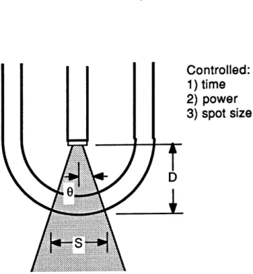
Controlled:
1) time
D
IS?
?
Figure II.1
Diagram
illustrating
the shortcomings of
the bare optical
fiber delivery scheme.
The
incident laser power and area of
tis-sue irradiated cannot be controlled.
the medium surrounding the
tissue may further change the
amount of light that reaches the tissue.
The laser exposure
time, which can be regulated by a
shutter in the laser beam proximal to the
optical
fiber,
is
the
only optical parameter that can be controlled. Hence,
controlled tissue removal cannot be achieved.
Figure II.2 illustrates how all of the optical parameters
CONTROLLED DELIVERY OF LASER ENERGY CONTROL OF OPTICAL PARAMETERS: THE OPTICAL SHIELD
optical
fiber in
a transparent, protective optical shield.
When the output surface of the shield is positioned in contact
with the tissue to be irradiated and removed, it locally
dis-places any blood or other intervening fluid to provide a clear
field between the tip of the fiber and the target tissue. All
of the laser power emerging from the optical fiber reaches the
tissue surface
(minus the known reflections at the inner and
outer surfaces of the shield).
Since the optical fiber can be
rigidly fixed
inside
the
shield, the distance between the
fiber's output tip and the tissue surface is fixed, fixing the
distance 1 and thus the spot diameter, and defining the area
of tissue to be
irradiated.
With the
incorporation of
a
shutter to control exposure time, all optical parameters are
controlled.
To a large extent, it would be possible to insure control
over all three laser parameters by bringing the output end of
an
optical
fiber into direct contact with the tissue itself.
In this way, the optical fiber plays the role of
the
optical
shield, displacing intervening fluid and defining a treatment
area equal in size to the fiber's core. However, it
is
un-likely
that
the optical
fiber could withstand the violent
reaction produced during ablation.
In addition, the
optical
CONTROLLED DELIVERY OF LASER ENERGY CONTROL OF OPTICAL PARAMETERS: THE OPTICAL SHIELD
Controlled:
1) time
2) power
3) spot size
Figure II.2
Diagram illustrating the control allowed by incorporation of a transparent optical shield. The incident laser power and area of tissue irradiated can now be
con-trolled.
design by producing laser spot diameters which greatly exceed the diameter of the optical fiber.
A number of other parameters can be derived from laser power, exposure time, and spot diameter which, although not independent, are useful in describing the laser/tissue interaction and ablation parameters. They include the
CONTROLLED DELIVERY OF LASER ENERGY CONTROL OF OPTICAL PARAMETERS: THE OPTICAL SHIELD
delivered laser energy (E) (the product of laser power and
ex-posure time, E = Pt), the incident laser intensity (I) (the
ratio of power to spot area, I = P/A), and the fluence (0)
(the product of laser power and exposure time divided by spot
area, 0 = Pt/A).
II.3 OTHER ADVANTAGES OF THE TRANSPARENT OPTICAL SHIELD
Along with providing the required control over all three
optical parameters, the optical shield concept provides some
other important advantages. During ablation, the reaction at
the distal output tip of the optical fiber is violent, leading
to char formation, corrosion, and tip damage [1,2]. The
opti-cal shield can protect the delicate optiopti-cal fiber from this
potentially harmful environment. Fluid displacement should
reduce the unnecessary and undesirable heating of blood by
removing it from the light path. The blunt end provided by
the optical shield protects the artery from mechanical
per-foration by the sharp end of an optical fiber. The shield can
also be used to house additional optics, lenses, filters,
mir-rors, etc., if shaping of the laser beam is desired.
It is important to note that, although the optical fiber
is fixed within an enclosure, the optical shield differs
CONTROLLED DELIVERY OF LASER ENERGY OTHER ADVANTAGES OF THE TRANSPARENT OPTICAL SHIELD
light passes through the optical shield and irradiates the
tissue directly, the tissue is heated by the absorbtion of
laser light, and not by a hot surface. The rate of energy
transfer to the tissue is thus dictated by the laser power
alone, and not by thermal conduction from the shield to the
tissue. Thus, it may be possible to deposit energy into an
atheroma much more rapidly by direct irradiation using an
opt-ical shield than by thermal conduction using a metal tip.
It is also important to note that the optical shield
con-cept is effectual only if the shield is brought into contact
with the tissue to be removed. All three optical parameters
are controlled only under those circumstances.
II.4 SELECTION OF A LASER SYSTEM
Conceptually, the optical shield delivery scheme can be
used with any laser system or laser wavelength for which
opti-cal fibers (or an equivalent light guide) and an optical
shield material are available. Current commercially available
optical fibers transmit well at all visible wavelengths and
into the near infrared. Fibers are also available which
transmit near ultraviolet with mixed success. Shield
materi-als such as glass or quartz are readily available for all of
CONTROLLED DELIVERY OF LASER ENERGY SELECTION OF A LASER SYSTEM
the very high peak powers generated by pulsed laser systems
and laser wavelengths further in the ultraviolet and infrared
by optical fibers pose problems that have attracted a great
deal of attention, but are yet largely unsolved.
For this study, the argon ion laser was selected to
demonstrate the ability to use the optical shield concept as a
controlled laser light delivery scheme and to develop a laser
angiosurgery system. The results should be applicable to
CONTROLLED DELIVERY OF LASER ENERGY REFERENCES
REFERENCES
1. G. Lee, R.M. Ikeda, B.S. Kozina, D.T. Mason, "Laser Dis-solution of Coronary Atherosclerotic Obstruction", Am. Heart J., 102:1974 (1981).
2. D.S.J. Choy, S.H. Stertzer, H.Z. Rotterdam, M.S. Bruno, "Laser Coronary Angioplasty: Experience with 9 Cadaver Hearts", Am. J. Cardiol., 50:1209 (1982).
SECTION III
SINGLE FIBER SHIELDED DEVICE BEHAVIOR
III.1 OVERVIEW
A single fiber optically shielded device was constructed to deliver argon ion laser light in a controlled way. It was used to produce craters in atheroma to characterize the rate of tissue ablation, and the size and shape of the craters pro-duced. These experiments demonstrate that the use of the opt-ical shield delivery scheme makes precise, quantifiable ablation possible, and give some insight into how ablation proceeds.
The purpose of this study was to demonstrate the worka-bility of the optical shield concept and gain knowledge neces-sary to develop an ablation system based on that concept. A larger study designed specifically to investigate ablation thresholds and evaluate the accuracy of the theoretical model using similar single fiber shielded devices is being
SINGLE FIBER SHIELDED DEVICE BEHAVIOR OVERVIEW
undertaken as a collaborative effort at the Cleveland Clinic
Foundation [1].
III.2 EXPERIMENTAL METHODS
The optical shield laser catheter constructed for these
studies consisted of an optical fiber with a carefully cleaved
or polished output tip rigidly centered inside a transparent
shield (Figure III.1). The fiber had a 133um core diameter
and a numerical aperture of 0.21. The shield was formed by a
length of 0.5mm thick quartz tubing of 3mm outer diameter,
closed at one end with a torch to form a hemispherical output
surface. The spot diameter (measured on the output surface of
the shield) was adjusted by choosing the appropriate distance
between the tip of the fiber and the output surface. Reticon
linear diode array measurements showed the beam profile to be
approximately uniform across the spot, falling rapidly to zero
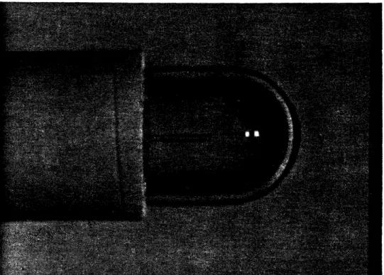
at the edges (see Figure III.2). Spot diameter was measured
by immersing the device in a bath of water containing a small
amount of rhodamine laser dye to permit visualization of the
beam (see Figure III.3). The beam was observed perpendicular
to the axis of the device with a dissecting microscope, and
SINGLE FIBER SHIELDED DEVICE BEHAVIOR
EXPERIMENTAL METHODS
a reticle.
+ 25um.
Spot diameter determinations were accurate to
Figure III.1
Optically shielded single fiber device.
Tissue ablation studies were performed using blue-green
light (all lines) from a Coherent I-20 argon ion laser. Human
atherosclerotic
carotid artery obtained at autopsy was cut
open lengthwise to expose the luminal surface. Samples,
typi-cally
1mm thick, exhibited relatively acellular intimal
SINGLE FIBER SHIELDED DEVICE BEHAVIOR EXPERIMENTAL METHODS
Figure 111.2
Single
fiber shielded device output
pro-file measured with a Reticon linear diode
array.
overlaying media, and were selected for sample to sample
uni-formity.
Each sample was placed in a petri dish and
immersed
in
either blood or saline solution. The tip of the optical
shield was brought into perpendicular contact with the luminal
surface, displacing the intervening fluid, and pressed against
it with a force of one ounce (0.28N).
Laser power was
meas-ured
at
the output surface of the device to an accuracy of
SINGLE FIBER SHIELDED DEVICE BEHAVIOR EXPERIMENTAL METHODS
Figure 111.3
Single fiber shielded device output as visualized by immersing the device in a bath containing laser dye.
by an electronic shutter placed in the laser beam, were ac-curate to +2msec. Saline was used in most studies, since the dimensions of craters produced in blood and saline were found to be the same within experimental variability.
The craters formed by laser ablation were roughly cylindrical with rounded bottoms. Crater diameter (d) was measured at the luminal surface of the tissue using a
SINGLE FIBER SHIELDED DEVICE BEHAVIOR EXPERIMENTAL METHODS
dissecting microscope with an eyepiece reticle. Crater depth
(1) was measured using a histological microscope with a
cali-brated fine adjustment focusing knob, bringing first the
tis-sue surface and then crater bottom into focus. Measured
crater dimensions were accurate to +25um.
Craters were randomly selected for histological
examina-tion. Each was
fixed
in
formalin, embedded
in
paraffin,
serially sectioned,
and hematoxylin and
eosin stained to
determine the degree of peripheral damage.
For each combination of
ablation parameters of laser
power (P) and spot diameter, the ablation velocity (v), or the
rate of
change of
crater depth with exposure time (t), was
computed as the ratio:
v = Al/At.
III.3 RESULTS
Three separate experiments were performed to characterize
the ablation process under varying ablation parameters and
conditions.
In
all
cases, mean crater depths and diameters
were computed from at least six individual craters. The mean
values are reported, along with error bars indicating the
en-tire range of values, for each set of ablation parameters.
SINGLE FIBER SHIELDED DEVICE BEHAVIOR RESULTS
III.3.1 Variation in Ablation Rate with Varying Power
The existence of a power dependence on the rate of tissue
ablation and crater formation was examined by producing
craters using single laser exposures through a shielded device
with a 750um spot diameter. Craters were made with several
different exposure times at 2.5W, 5.0W, 7.5W, and 10.0W.
The craters produced were relatively free of char at all
power levels and exposure times, with a slight increase in
char production at lower powers and longer times. Histology
showed a narrow layer of vacuolation and hypereosinophilia
surrounding the crater. A region beyond that showed slight
collagen alteration typified by an increase in unstained space
without hypereosinophilia. The structure of the arterial wall
did not appear to be compromised by this change. A typical
histological section is shown in Figure III.4. Occasional
splits in the media were observed radiating from the produced
crater in many cases. Qualitatively, the thickness of the
layers of vacuolation and collagen alteration decreased with
decreasing delivered energy, that is, with decreasing power at
the same exposure time and with decreasing exposure time at
the same power. Almost no vacuolation or collagen alteration
SINGLE FIBER SHIELDED DEVICE BEHAVIOR RESULTS