Design and Control of a Nonlinearly Compliant Robotic Finger
by
Vinay Kishore Shah
B.S., Mechanical Engineering
University of California at Berkeley, 1994
Submitted to the Department of Mechanical Engineering
in Partial Fulfillment of the Requirements for the
Degree of
Master of Science in Mechanical Engineering
at the
Massachusetts Institute of Technology
September 1997
01997 Massachusetts Institute of Technology
All rights reserved
Signature of Author:
Certified by:
Departme
f Mechanical Engineering
August 8, 1997
\
Dr.
J.
Kenn
alisbury Jr.
Principal Res. ch Scientist
Thesis Supervisor
Accepted by:
-A. -A. Sonin
Professor of Mechanical Engineering
Chairman, Committee for Graduate Students
Design and Control of a Nonlinearly Compliant Robotic Finger
by
Vinay Kishore Shah
Submitted to the Department of Mechanical Engineering on August 8, 1997 in Partial Fulfillment of the Requirements for the Degree of Master of Science in
Mechanical Engineering
ABSTRACT
In this work an inexpensive, modular robot finger was designed and developed with exponentially
stiffening springs between the actuators and joints. Controlling the deflection of these springs is equivalent to controlling force, since the deflection is directly related to the applied force through the spring's
force-deflection curve. Therefore, the use of compliance in the joints transforms the problem of force control into one of position control, thereby simplifying force control algorithms, improving performance, and allowing the use of small, cheap, gear-reduced actuators. Furthermore, the exponential nature of the compliance allows a constant percentage resolution of forces that can be exerted and sensed. This constant percentage resolution leads to an extremely large dynamic range and excellent contact sensing ability. These traits are also present in humans, and have been identified as essential to the dexterity of human fingers.
The finger was designed with three degrees-of-freedom and kinematics similar to that of human fingers. The fingers can be used in combination to form a hand capable of grasping and grasp gait experiments, or individually for palpation and perception experiments. The modularity of the fingers permits variable hand configurations and allows manipulation of objects with a wide range of size and shape. Furthermore, modularity helps to reduce the cost of a complete hand, since fewer unique parts are required.
A control structure for precise application of torque through these exponential springs was devised, and the
performance enhancements were quantified using a single-axis test stand that isolated one actuator and compliant element. The control algorithm consists of a high gain, high bandwidth inner motor position control loop, and a lower bandwidth outer torque loop. The torque resolution using this system remained
constant at 5% regardless of the magnitude of the forces, and was exactly equal to the resolution of the
spring deflection sensor. This resolution leads to a dynamic range of over 1000, a factor of 30 increase over the gear-reduced motor alone. However, the use of compliance limits the bandwidth of the actuator to about 10Hz. It is expected that this reduction in bandwidth will not have a significant effect in finger and hand applications, since grasping and grasp gait tasks require low bandwidth movements.
Three of these torque control blocks were combined, along with additional layers for simple path planning and desired joint torque calculation, to form the basis for the finger control algorithm. However, a high performance fingertip position and force control algorithm was not realized. But, it was shown that the basic torque control structure used successfully on the single-axis system can also be used in the multiple-axis case, despite the cross-multiple-axis coupling and changing load torque and inertia. Additional research is required to achieve fingertip force control performance equivalent to that achieved in controlling an isolated torque on the single-axis test stand.
Thesis Supervisor: Dr. J. Kenneth Salisbury Jr. Title: Principal Research Scientist
Acknowledgements
This work would not have been possible without the support and guidance from my advisor, Dr. Ken Salisbury. Ken has been very helpful with his vast experience with robot hands and his unique insights. It has been a genuine pleasure working with him.
I would also like to thank the rest of Ken's research group, especially Akhil Madhani, Craig Latimer,
Gunter Niemeyer, and Brian Anthony. They were always around and willing to help me with design and control issues, and to give me some fresh ideas and viewpoints.
Thanks also to all my friends at MIT who have made my stay here enjoyable and filled with so many fond memories. My two best friends, Loreli Cadapan and Craig Latimer, have been there for me through thick and thin. Loreli has been supportive and helpful from the beginning, and even helped put this report together. Craig was always willing to fly over the handlebars with me at Lynn Woods when the lab was just too unbearable.
And last but not least, I would like to thank my family who have always given me the most unconditional love and support anyone could ask for. My parents and sister have always believed in me. Their encouragement helped me get through the times when I thought I would never finish.
Finally, I would like to gratefully acknowledge the financial support of the Office of Naval Research, University Research Initiative Program, Grant N00014-92-J-1814, without which this project would never have gotten off the ground.
There are many others who are not named here but whose contributions to my thesis and my delightful experience at MIT will always be remembered.
Contents
List of Figures 6
1 INTRODUCTION 7
2 MOTIVATION FOR A NEW HAND 8
2.1 Overview of Existing Hands
9
2.2 Limitations of Existing Hands 11
2.3 Performance of Human Hands
11
2.4 Goals of New Robot Finger
13
3 METHOD OF PERFORMANCE ENHANCEMENT 14
3.1 Traditional Stiff Transmission Design
14
3.2 Enhanced Performance Through Compliance
15
3.2.1 Benefits of Exponentially Stiffening Springs 16
3.3 Other Methods of Improving Performance 17
4 COMPLIANT ELEMENT 18
4.1 Mechanical Design
18
4.2 Instrumentation
20
5 SINGLE-AXIS TEST STAND 22
5.1 Mechanical Setup
23
5.2 Controller
24
5.2.1 Loop Stability 26
5.2.2 Filters 27
5.2.3 Selection of Time-Varying Gains 27
5.2.4 Controller Modifications 30
5.3 Performance
31
5.3.1 Trajectory Tracking 32 5.3.2 Performance Measures 36 5.3.3 Bandwidth 37 6 FINGER DESIGN 396.1 Kinematics
39
6.2 Link Lengths
40
6.2.1 Jacobian 41 6.2.2 Results of Calculations 416.2.3 Actual Link Lengths 42
63 Drive Assembly
42
6.4 Cable-Pulley System
45
6.5 Finger Links
46
6.6 Actuation
47
7 FINGER CONTROL AND PERFORMANCE 49
7.1 Three-Axis Controller 49
7.2 Controller Performance 51
8 NEW FINGER DESIGN 54
8.1 The Drive Assembly 57
8.2 Cable/Pulley System 59 8.2.1 Cable rubbing 59 8.2.2 Cable Tensioning 60 8.3 Finger Links 61 8.4 Simplified Machining 62 9 SUMMARY 63 References 65
List of Figures
Figure 1: Salisbury Hand 10
Figure 2: Utah/MIT Dexterous Hand 10
Figure 3: Torque vs. Deflection Curve for the Compliant Element 19
Figure 4: Potentiometer Amplifier Circuit 21
Figure 5: Amplified Pot Output vs. Input Shaft Position 21
Figure 6: Single-Axis Test Stand 23
Figure 7: One-DOF, Fixed-End Model 24
Figure 8: Two-Inertia Model 24
Figure 9: Controller Schematic Diagram 25
Figure 10: 5 mNm Step Response w/o Integrator Windup Protection 30
Figure 11: 40 mNm Step Response w/o Integrator Windup Protection 30
Figure 12: 40 mNm Step Response With Integrator Windup Prevention 31
Figure 13: 150mNm Step Response With Integrator Windup Prevention 31
Figure 14: Step Tracking Performance 33
Figure 15: Sinusoidal Tracking Performance 34
Figure 16: Rejection of Continuous Random Disturbances by Torque Controller 35
Figure 17: Rejection of Large Spike Disturbances by Torque Controller 35
Figure 18: Frequency Response of the Overall Torque Control System 38
Figure 19: Frequency Response of the Inner Loop PD Position Controller 38
Figure 20: Original Finger Design 39
Figure 21: Chosen Finger Kinematics 40
Figure 22: Locus oflsotropic Points 42
Figure 23: Drive Assembly 43
Figure 24: Compliant Element 1 Cable Transmission and Tensioning 44
Figure 25: Compliant Element 2 and 3 Cable Termination and Tensioning 45
Figure 26: "Alpha Loop" Around Idler Pulley 46
Figure 27: Link 1, the "knuckle" 47
Figure 28: Link 2 and Link 3, the "digits" 47
Figure 29: Schematic of Three-Axis Control System 49
Figure 30: Joint Torque Step Tacking w/Fixed Fingertip 52
Figure 31: Joint Torque Sinusoid Tracking w/Fixed Fingertip 53
Figure 32: Gravitational Torque Tracking While Finger is Manually Moved 54
Figure 33: New Finger Design 56
Figure 34: Front and Side Views of Lower Actuator in New Design 58
Figure 35: Cable Routing Over Double Idler Pulleys 59
Figure 36: Cable Loses Contact With First Pulley 60
Figure 37: Cable Tensioning in the New Finger Design 61
1
INTRODUCTION
Since the inception of the field of robotics over fifty years ago, scientists and engineers have raced to build robots with ever-increasing capabilities. These robots evolved from simple devices designed for specific tasks, to more complex mechanisms with broad applicability. However, robotic end-effectors have not
experienced the same level of development. On the contrary, modem industrial end-effectors are still
highly specialized devices designed for very specific tasks, despite a significant effort in the robotics
community to develop more general end-effectors, such as multi-fingered hands. Advances at the research level have not been adopted by industry, partially because of the enormous cost and complexity of the mechanisms and control strategies that were developed. These issues were addressed in this work by designing, constructing, and controlling a low cost, high performance robotic finger. This modular finger
can be used as a baseline for the development of inexpensive, hand-like end-effectors capable of executing a wide range of dexterous manipulation tasks.
The earliest robots were master-slave mechanisms, where a master manipulator was manually operated by the user, while the mechanically coupled slave unit mimics every movement of the master. These robots were designed for very specific applications, since the requirement of mechanical linkages to connect the master anrd slave prevents generic-system design. However, the mechanically linked slaves eventually gave way to independently actuated mechanisms and the master teleoperators were replaced by computer control, which opened the door for the development of multi-purpose robots. Today, many different six degree-of-freedom (DOF) robot arms exist, such as the Stanford Arm, Schilling Arm, and Whole Arm Manipulator (WAM). Although there are many fundamental differences among these robots, they are all capable of exerting large forces and moving and positioning in a precise manner within a large workspace, making them suitable for many different purposes.
End-effectors are typically mounted on the end of these multi-purpose manipulators, and are the interface between the arms and the environment. Although today's end-effectors can accomplish complex and delicate tasks such as assembly involving mating parts or integrated circuits, they are usually highly specialized devices and are limited to the particular task for which they were designed for several reasons. First, they lack the dexterity to manipulate a grasped object, so the orientation in which the object is presented to the end-effector must be precisely controlled. Second, the size and shape of graspable objects and the number of possible grasps on these objects are limited, so end-effectors must frequently be changed for different tasks. Finally, they lack the ability to accurately exert both large forces and small forces, which further limits their applicability.
In response to these issues, a significant effort by the robotics research community for many years has focused on the development and control of multi-fingered, articulated hands to be used as general purpose,
dexterous end-effectors. Results of this research include the Salisbury Hand and the Utah/MIT Hand, which are force-controllable, three- and four-fingered hands capable of extremely dexterous manipulation of a wide range of objects. However, the vast potential demonstrated by these devices has not been realized because of the enormous cost and complexity of the mechanisms, as well as the algorithms and
computational resources required to control them.
In this work, an inexpensive, high performance robotic finger was developed to be the basis for a new dexterous hand. The finger uses exponentially stiffening springs between the motors and finger joints to achieve intrinsic mechanical compliance. This compliance allows the use of inexpensive actuators and sensors and a relatively simple control strategy to achieve performance characteristics identified as essential for dexterous manipulation, such as force controllability, dynamic range, and accurate contact sensing. Although a robotic hand composed of these fingers is by no means ready for industrial use, it is hoped that further work exploring its full capabilities will trigger a new wave of hand research, which, in turn, will eventually lead to the success of dexterous robot hands outside of the laboratory.
The remaining chapters of this paper will discuss in more detail existing dexterous end-effectors and the motivation for designing a new one. It will then describe how the use of intrinsic mechanical compliance can help to improve dexterity and performance, while decreasing costs and simplifying the mechanics and required control strategies. Chapter 4 will then describe the design of the compliant elements used to impart intrinsic flexibility to the mechanism. Next, a strategy for precisely controlling the torque output of this compliant element is presented, and the performance of this controller is quantified. The following two chapters discuss the design of a three-DOF finger that uses these compliant elements, and the implementation and evaluation of a torque controller for the finger joints. An improved finger design is then presented in Chapter 8 before finally summarizing the work presented here.
2 MOTIVATION FOR A NEW HAND
Researchers and engineers worldwide have developed dozens of mechanical hands, ranging from prosthetic devices to multi-fingered robot hands for dexterous manipulation. The most famous of these are the Salisbury Hand and the Utah/MIT Hand. Despite their enormous potential, none of these mechanisms have achieved widespread success in industrial settings, nor have they become commonplace in the research community. Among the reasons for this are their costs of production and operation and their complexity of control. Furthermore, the capabilities of existing robot hands pale in comparison to human hands. Current mechanical hands cannot robustly perform many basic tasks that humans can do, such as grasp gaits, which are large scale re-orientations of objects while maintaining a stable grasp. A need exists for a robotic hand that can begin to approach the performance of human hands, while maintaining low cost, simplicity of
control, and ease of operation. The modular finger designed in this work is meant to be the basis for a new hand that fulfills this need.
2.1
Overview of Existing Hands
The idea of mechanical hands is certainly not a new one; it has been in existence for hundreds of years. In fact, one of the earliest devices referenced in the literature was built in 1509 for a knight who had lost his hand in battle [Childress, 1972]. This hand and most of the other hand mechanisms developed before the
1960's were intended for prosthetic applications [Murray, 1994], evolving from simple, cosmetic
attachments to body-controlled mechanisms and, more recently, even externally-powered, myoelectrically controlled devices [Jacobsen, 1982].
However, in the last 30 years, the desire to manipulate objects in remote or hazardous environments and to automate assembly or manufacturing processes has driven the development of computer-controlled, dexterous, multifingered hands. These devices were intended to be teleoperated "slaves" or dexterous end-effectors for other robots. Some of the first of these mechanisms were designed
by Skinner [Skinner, 1975], Crossley [Crossley, 1977], Hanafusa and Asada [Hanafusa, 1982], and Okada
[Okada, 1982]. Most of these hands were limited in functionality to simple grasping maneuvers, although the Okada hand, a three-fingered, cable-driven device, was able to perform slightly more complex tasks such as screwing a nut onto a bolt.
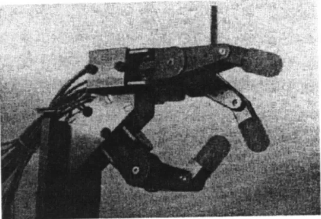
The most capable and most famous robotic hands were the Salisbury Hand [Salisbury, 1984], shown in Figure 1, and the Utah/MIT Dexterous Hand [Jacobsen, 1984], shown in Figure 2. The Salisbury Hand consisted of three cable-driven fingers, each with three degrees-of-freedom (DOF) actuated by electric DC motors. The fingers were placed in a human-like configuration such that one finger (the "thumb") opposed the other two, which were placed adjacent to each other. The Utah/MIT Hand was even more anthropomorphically inspired, and consisted of three fingers and a thumb with 4 DOF each. The fingers and thumb closely resemble their human counterparts in appearance, kinematics, range of motion, and location on the palm, which also was designed to look similar to a human palm. Each finger joint was driven by cable tendons, as with the Salisbury Hand, but the Utah/MIT Hand was actuated by pneumatic pistons. These hands were able to grasp a huge range of objects and perform many complex manipulation tasks.
Figure 1: Salisbury Hand
Figure 2: Utah/MIT Dexterous Hand
The introduction of these two hands triggered a flurry of research activity in the area of dexterous manipulation. Some of the products of this research are newer robotic hands like the five-fingered Anthrobot-2 [Ali, 1993] and the Four-Fingered JPL Hand [Jau, 1992]. Both of these new hands are
extremely human-like in form. In fact, the primary design goal for the Anthrobot-2 was to create a hand that is identical to human hands in number of fingers, number of joints per finger, placement and motion of the thumb, proportions of the link lengths, and shape of the palm.
The Four-Fingered JPL Hand goes a step further by including an anthropomorphic wrist and part of a forearm. Interestingly, the JPL Hand has five active compliance adjusters for independent modulation of the stiffness of each of the four complete fingers and the wrist. An exoskeletal glove controller is used for teleoperation of the hand.
2.2 Limitations of
Existing
Hands
Despite their tremendous dexterity and versatility compared to most industrial robotic end-effectors, robot hands have not been widely used for industrial purposes. Instead, highly specialized devices are designed
for individual applications. These devices lack the adaptability to meet the needs of changing
environments and task requirements, so new robots or end-effectors are required whenever manufacturing lines change. Nevertheless, they are the standard of industrial automation, because current robot hands
require more complex control strategies, are extremely expensive, and are more difficult to operate.
Hand programmers have been able to perform marvelous tasks with current robot hands, such as executing basic grasp gaits [Fearing, 1986], but only with monumental control effort. Not only are the path and grasp planning algorithms complex, but also the underlying structure for control of the fingertip contact forces. Recognizing that compliance can improve force control performance, some researchers even attempt to mimic variable compliance with software algorithms [Hogan, 1985]. However, this active approach to
force and compliance control is limited in bandwidth and resolution, and requires extensive computational resources.
Another problem is that current hand mechanisms are just too expensive to be used in an industrial setting. The Salisbury and Utah/MIT Hands ranged in price from around $40,000 to $100,000, although these numbers would probably be significantly lower if demand were enough to justify larger production volumes. In contrast, most industrial end-effectors can be produced for just a fraction of that price because of their simplicity of design, fewer actuated degrees-of-freedom, and reduced sensor and actuator
requirements.
An additional reason why these hands have not gained widespread popularity is that they are not
particularly convenient to use. The Utah/MIT Hand requires a small room to house all the air compressors, pressure regulators, and other components that drive the pneumatic pistons. And, the Salisbury Hand has a separate, 12 pound, drive package consisting of the motors, gear reductions, and cable tension sensors. Although much more compact than the Utah/MIT Hand's compressors, this drive package represents a significant load when mounted to the end of an arm, limiting the arm's capability to perform useful work.
2.3 Performance of
Human
Hands
Human hands are unequaled by their mechanical counterparts in dexterity, sensitivity, and adaptability. Humans can achieve stable grasps on a huge range of objects varying in size, shape, weight, surface texture, etc. The grasps can be extremely stiff or extremely flexible, and can have large contact forces or small contact forces. The contacts can be with the fingertips, the walls of the finger, the palm, or any
combination of the three. Moreover, humans can reorient the grasped object while maintaining a stable grasp, a process known as finger or grasp gaiting. The performance characteristics of human hands that allow these great capabilities has been a subject of research for many years. Some results of this research point to characteristics such as an extreme range of forces that can be exerted and sensed, excellent resolution of forces within that range, the ability to accurately detect contact with the grasped object, and the capacity to modulate the grasp and finger stiffness [Leveroni, 1997].
It appears that one of the key traits that give human hands their incredible dexterity is dynamic range, defined as the ratio of the largest to smallest force that can be exerted or sensed. The human fingertip can exert both extremely large forces and minutely small ones, giving a dynamic range on the order of 10000:1 [Srinivasan, 1993]. In contrast, very good multi-DOF robots are usually limited to a dynamic range of only about 100:1 [Morrell, 1995].
In addition to large dynamic range, the percentage resolution of forces that can be exerted and sensed remains nearly constant throughout that entire range. This resolution is the smallest percentage change in force that can be distinguished (Just Noticeable Difference, JND) or exerted (Just Controllable Difference, JCD) by the human fingertip. By applying varying contact forces to the fingerpad of human subjects, researchers have determined that humans can perceive a percentage change in force that is independent of the magnitude of the force. This JND has been reported to be between 7% [Pang, 1991; Tan, 1992] and
10% [Clark, 1986; Jones, 1989]. Similar experiments have shown that humans can exert a constant JCD
(with tactile feedback only) of between 11% and 15%, regardles of the size of the forces [Srinivasan,
1993]. Interestingly, Srinivasan noticed that when a visual display of the contact force and force error was
provided, subjects could effect a constant absolute change in force, giving a percentage resolution that decreased with force magnitude.
A third important characteristic of human fingers that leads to dexterity is the ability to detect contact. In a very basic sense, manipulation can be thought of as a pattern of intermittent contact between the fingers and the manipulated object, so fingers that can accurately detect when and where these contacts occur are more effective at manipulation. Humans are exceptional at detecting these contacts because of their vast number of tactile receptors on the fingertip.
A fourth trait that human fingers have that aids in dexterous manipulation is the ability to modulate finger
and grasp stiffness due to the variable compliance intrinsic to finger joints. Through co-activation of antagonistic muscles within a finger, humans can vary the stiffness of the finger itself, making it rigid or flexible without even making contact with the environment. Similarly, co-activation between fingers allows humans to modulate the stiffness of a grasp when multiple fingers are in contact with the same
object. Some scientists believe that this ability to modulate stiffness by co-activation plays an important role in dexterous manipulation [Hogan, 1988].
2.4
Goals of New Robot Finger
The goals of this work were to design a modular robot finger that is intrinsically force controllable, has a large dynamic range, has a constant percentage force resolution, and is inexpensive and compact, and to devise a strategy for precise control of fingertip forces. Unlike many previous robot fingers and hands, this finger is not required to be aesthetically human-like. Instead, the goal is to mimic the performance and dexterity of human fingers to create a more capable robot.
These modular fingers can be used as the basis for a multi-fingered hand to be used for grasping and grasp gait experiments. Modularity allows the number and location of the fingers to be reconfigured for particular object sizes and shapes, yielding a huge range of objects that can be grasped and manipulated. Modularity also helps to minimize cost of a complete hand, since multiple finger copies means fewer unique parts and higher production volumes. Furthermore, the finger can be used singly for palpation and perception experiments on the human haptic system.
Force controllability, dynamic range, and force resolution were achieved by adding mechanical compliance to each joint of the finger in the form of exponentially stiffening springs. This flexibility, similar to the natural compliance found in human finger joints, improves force control performance because position control algorithms can be used to control force. The exponential nature of the compliance provides large dynamic range and constant percentage resolution of exerted and sensed forces. A more detailed explanation of performance benefits of exponential compliance is given in Chapter 3.2.
In addition, these springs help to reduce the cost of the finger by allowing the use of small, off-the-shelf, gear-reduced motors to actuate the joints without compromising force control performance. The small, gear-reduced motors can be used because the springs return to the actuator many qualities that are initially lost when gearheads are introduced, as described in Chapter 3.2. Furthermore, the spring also functions as a torque sensor when equipped with a potentiometer or optical encoder to measure its deflection, so additional force sensing devices are not required.
The use of these small motors and integrated torque sensors also helps to make possible small finger linkages, drive mechanisms, and actuator packages. This yields a simple and compact device that can more easily be appended to an arm without overloading the supporting robot.
Finally, antagonistic actuators were considered, but not incorporated in the final design, although they are believed to be important in human dexterity. The use of antagonistic actuators would allow modulation of finger stiffness, but it also doubles the number of required actuators and sensors, increases the complexity of the mechanical and control systems, and reduces the compactness of the device. However, even without antagonistic actuators, modulation of grasp stiffness by co-activation between fingers is still possible, and is the basis for the planned improvements in the ability to grasp and manipulate objects. Should it be deemed necessary, additional actuators can be added in the future by slightly modifying the drive mechanism.
3 METHOD OF PERFORMANCE ENHANCEMENT
Robotic manipulators have traditionally been designed with transmissions that are as stiff as possible to maximize bandwidth. These systems are excellent for position control, but are not well suited for force control due to low dynamic range and sometimes also low force resolution. Recently, researchers have used linearly compliant transmissions to improve dynamic range and force control, at the cost of decreased bandwidth. In this work, an exponentially compliant transmission was developed to further enhance performance. Although the work presented here focuses on implementing compliance in a robotic finger, the basic design and control methodology can be applied to create other types of dexterous manipulators.
3.1
Traditional Stiff Transmission Design
Traditionally, engineers and designers have attempted to maximize the performance of their systems by making the transmission between actuator and load as stiff as possible [Townsend, 1988; Eppinger, 1989; Readman, 1994]. This type of mechanism is excellent for fine position control and rapid trajectory tracking since stiffness accommodates fast, high bandwidth controllers. Furthermore, systems with stiff transmissions can even tolerate high controller gains when the sensors are located at the load, without the usual instability problems associated with non-collocated control [Canon, 1984]. Many high performance robots have been built using this philosophy, including the WAM [Salisbury, 1989] and the PHANToMTM [Massie, 1994].
However, there exist several drawbacks to the use of stiff transmissions for force control. First, in direct-drive systems, the dynamic range is usually restricted to around 100:1 due to limitations of electric motors [Morrell, 1995]. Therefore, motors that can accurately exert small forces cannot provide large forces that are necessary for stable grasping, while larger motors that can exert large forces cannot accurately provide the small forces that are necessary for fine manipulation.
Second, stiff transmission designs introduce performance and reliability issues when gear reductions are used. Motors with gearheads are commonly required when cost and size are design factors, since small, cheap, geared motors can produce the same peak torque as a large motor at a fraction of the price. Furthermore, gearheads are often required to support heavy loads even when large motors are used, because many electric can only produce high power at high speed [Hunter, 1991]. These gearheads add friction, torque ripple, and backlash to the system, and can easily be damaged or even cause damage to objects in the workspace. Friction lowers the dynamic range even further, torque ripple adds errors to the output torque, and the backlash produces uncertainty in the endpoint position and also induces limit cycling in non-collocated systems. Damage to the gearhead often results from shock loads caused by collisions
with the environment, because the high reflected inertia (N2 increase in reflected inertia for an N: I
gearhead) produces enormous forces on the gear teeth. Sometimes these collisions can even result in damage to the environment, due to the high backdrive friction and reflected inertia of geartrains [Pratt,
1995].
Finally, force control of a stiff mechanism with gear-reduced actuators usually requires complex force control strategies and high data rates between the computer and the motors and sensors. Some control methods even attempt to mimic variable mechanical compliance through active impedance control [Hogan,
1985], but only at the cost of a very large control effort.
3.2 Enhanced Performance Through Compliance
Improving dynamic range and force control performance by adding mechanical flexibility to a mechanism is a relatively new technique in robot design and control. However, aerospace and structural engineers have developed control strategies for flexible systems, such as those found on satellites and other space structures for decades [Balas, 1977]. Other researchers have added flexible coverings to end-effectors to stabilize force control during intermittent contact with hard surfaces by creating compliance in the interface between the robot and the environment [Hogan, 1989; Whitney, 1987]. But, until recently, engineers have not intentionally added compliance to the transmission between actuator and robot as a means of improving performance.
One key benefit of compliant transmissions is that force control is transformed into the easier problem of position control. Since the output force is directly related to the deflection across the transmission, controlling this deflection is equivalent to controlling the force. Furthermore, position can be accurately controlled through a gearhead, resulting in precise force control and virtually eliminating the harmful effects of gearhead friction and torque ripple.
Also, the compliance in the transmission has a low-pass filter effect on loads applied to the robot by the environment. Therefore, peak forces on the gear teeth due to shock loads on the robot are drastically reduced, lowering the likelihood of damage to the gearhead or the environment. However, this low-pass filter also acts on forces transmitted from the actuator to the robot, so the bandwidth of the system is reduced as well. But, dexterous manipulation tasks do not require high bandwidth movements, since human fingers have a bandwidth of only around 7-20 Hz [Srinivasan, 1994; Brooks, 1990]. Therefore, it is expected that this decrease in bandwidth will not drastically affect the grasping and manipulation
performance of the compliant finger developed here.
Other researchers have used both passive and actively controlled springs to improve force control
performance of manipulators. Pratt and Williamson [Pratt, 1995] developed a series elastic actuator using passive linear springs between the motor and load, developed a simple, effective, and stable force control architecture, and successfully implemented it in the MIT humanoid robot Cog [Brooks, 1994]. Sugano
[Sugano, 1992; Morita, 1995] controlled contact forces on a one-DOF robot finger and arm that incorporated actuator-controlled spring stiffness and damping. Tasch [Tasch, 1996] controlled fingertip position and compliance of a two-DOF finger that also used actively-controlled spring stiffness. The work involving actively controlled springs is most similar to human fingers, since it simulates antagonistic muscles which can modulate joint stiffness independently of joint position or contact force. However, these systems require several additional actuators and increased controller complexity, which is not compatible with many goals of this design.
3.2.1 Benefits of Exponentially Stiffening Springs
Our work compliments and extends the work of the above researchers by using passive, exponentially stiffening springs to impart nonlinear compliance to the transmission. Exponentially stiffening compliance was chosen because it produces a constant percentage force resolution for control and sensing over an extremely large dynamic range, a desirable trait that is also found in the human haptic system, in addition to the other benefits of compliance described above.
Applying torque with a DC motor through an exponentially compliant transmission produces a constant percentage torque resolution because of the manner in which torque is produced and measured. Torque is produced by positioning the motor to create a deflection of the exponential spring, and the magnitude of the torque can be computed by measuring this deflection. But, motor positioning and spring deflection measuring are accomplished with fixed-resolution sensors (such as encoders or potentiometers), while the torque per unit deflection increases as the torque level increases due to the stiffening nature of the spring. Therefore, at low torque levels, the spring exhibits low stiffness, so a unit change in spring deflection produces a very small change in output torque, yielding a fine absolute torque resolution. At high torque
levels, the spring is stiff, so the same unit change in spring deflection produces a much higher change in torque, yielding a coarse absolute resolution. However, the percent change in torque and percent resolution is exactly the same in both cases, as can be seen in the following derivation that compares resolution with
linear springs and exponential springs:
Linear Spring
F
=
kO
Fo = kOo,
F, + AF= k(9, + AO)
AF
AO
percentage force resolution is dependent on original
deflection
force-deflection relationship of the spring a nominal spring deflection produces a
nominal torque
an additional unit deflection produces a change in force
the percentage resolution in force
Exponential Spring F = AeBO Fo = AeBo,
F,
+ AF = AeS(.o+A°)AF
e BAO1F
percentage force resolution is independent of original deflection and is constant for a
given AO
This constant percentage resolution is desirable because it provides adequate force resolution for different types of tasks over an extremely large dynamic range. Extremely fine resolution at low forces aids in
performing delicate manipulation tasks, which requires small, precise forces. Lower resolution at high forces is sufficient for coarse manipulation tasks, such as lifting rugged objects. In contrast, a linearly compliant system that provides fine small-force resolution could not achieve a large dynamic range (without huge spring deflections), and a system that can exert large forces could not give adequate resolution at low forces.
3.3 Other Methods of
Improving
Performance
Another method of increasing dynamic range and force control performance is the micro-macro approach. In this technique, a large (macro) motor provides the main component of output torque, while a much smaller (micro) motor superimposes an additional component of torque. In this system, the large motor is responsible for coarse torque control, while the small motor handles fine control.
A micro-macro actuator system can be used to achieve precise force control and large dynamic range, without the bandwidth limitations present in flexible systems or the backlash, friction, and reflected inertia found in gear-reduced systems [Sharon, 1993]. Morrell [Morrell, 1995] constructed a micro-macro actuator that achieved a dynamic range of about 800 and a bandwidth of nearly 60 Hz.
However, this type of system doubles the required number of actuators, requires larger motors, and increases the complexity of the mechanical system and control algorithms. For these reasons, this method is not compatible with the goal of developing an inexpensive, compact, and easily controllable dexterous end-effector.
4 COMPLIANT ELEMENT
Custom designed compliant elements were inserted between the motor output shafts and finger joints to provide intrinsic mechanical flexibility to the joints and to function as a joint torque sensor. Each compliant element is a compact, self-contained, instrumented package containing an exponentially stiffening, torsional spring, a threaded capstan for wrapping the drive cables that actuate the joints, and a potentiometer to measure the angular deflection of the spring. The applied torque can be computed from the deflection measurement using the torque-deflection relationship of the spring, which was empirically determined.
4.1
Mechanical Design
The compliant element is a clutch-like mechanism consisting of two parallel aluminum disks with alternating radial walls extending from each disk. The front disk includes a clamping mechanism with which it is rigidly attached to the drive shaft. The back disk includes a threaded capstan for routing cables to the joints, and rotates about the shaft on a ball bearing. The radial walls create pie-shaped pockets on each disk, which are filled with 3/16" diameter rubber balls, through which torque is transmitted from one disk to the other. However, as the balls are compressed, they exert axial reaction forces that tend to push the two plates apart, so it is important to use a retaining ring behind the back plate to hold it in position. This design is cheap and extremely reliable, since there is only one moving part, only two parts require machining, and all components are made of durable and inexpensive aluminum and rubber.
The compliant element functions as a non-linear, exponentially stiffening spring and torque sensor. Any relative motion between the two disks causes the balls to be squeezed between the radial walls, creating the elasticity. Initially, the contact area between the walls and balls is extremely small (approaching point contact), so the stress is high for even small contact forces, yielding a low effective stiffness. As the contact forces increase, the ball deforms further, causing the contact area to increase. Because of this
Force
increase in contact area, the stress on the ball ( Stress = ) doesn't increase in proportion to the
Area
contact forces, thereby increasing the effective stiffness of the ball. As the ball continues to deform, it eventually fills the pocket completely. Any further rotation of the disks compresses the ball into itself and increases its bulk modulus, causing the stiffness to increase even faster, yielding the highly nonlinear stiffening characteristic.
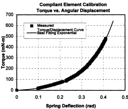
The actual spring torque vs. deflection curve was determined by locking one of the disks in place and attaching a 6" aluminum rod to the other disk. Weights were incrementally hung from the aluminum rod and the resulting deflection was measured with an HP HEDM-5500-J04 (1000 LPR) optical encoder. Figure 3 shows a graph of this data and the best-fitting exponential curve. The relationship and its derivative, which is the spring stiffness, are explicitly expressed in Equation 1.
700 600 -500
z 400
300 1'200 100 0iCompliant Element Calibration
Torque vs. Angular Displacement
0 0.1
0.2
0.3
Spring Deflection (rad)
0.4
0.5
Figure 3: Torque vs. Deflection Curve for the Compliant Element
T
=
A(e
"- 1)
k -
- ABeBO, where A = 14.0 and B = 8.6
Equation
1:
Spring Torque and Stiffness as a Function of Deflection
Equation 1: Spring Torque and Stiffness as a Function of Deflection
- - Measured . .
Torque/Displacement Curve -Best Fitting Exponential
--- --- - --- --- --- --- --- -- - - - -- - -- -- -- --- - - - -. . - -- . . - ..--- - -- - --. --- - -- -- ---- ---- -- -- - -- --- -- - --
-The six balls are made of acrylonitrile butadiene, a synthetic rubber also called Buna-N, NBR, or nitrile. This material was chosen for its excellent rebound characteristics, low compression set, and low friction. The composition, number or shape of these elastomers could easily be changed to tune the spring curve to any desired shape.
The pie-shaped pockets between the disks were designed so that the balls would be slightly preloaded in the neutral position (about .006" of compression). Because this preload effectively decreases the small-torque resolution, the amount of preload was made as small as practical to ensure zero backlash. Preload decreases resolution by shifting the torque-displacement relationship, which moves the origin to a steeper point on the curve.
4.2 Instrumentation
A Midori America Corporation model CP2U-TX magneto-resistive, panel-mount style, potentiometer was used to measure the angular deflection of the spring. This potentiometer functions by passing a magnet
over a material whose resistance changes when exposed to a magnetic field. The non-contact nature of the potentiometer, combined with its bearing-supported input shaft, provides an extremely smooth,
differentiable output signal. This output signal is linear with angular position over a ±450 range of motion, although the mechanical rotation is unlimited.
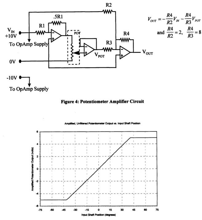
The output signal from the pot is amplified to maximize the signal to noise ratio and resolution. The raw signal varies between 1.5V and 3.5V; it is /2 of the +5V supply at the pot's neutral position, and varies linearly throughout the electrical range of motion by about ±20% of the supply voltage. However, this signal is susceptible to noise since it has a small voltage range and does not use the full input range of the
A/D board (-5 to 5V or 0 to I 0V). Therefore, the circuit shown in Figure 4 was used to shift the neutral
position voltage to OV and amplify the signal 8X, so that about ±400 of mechanical motion uses the entire ±5V range of the board. The output of the circuit vs. potentiometer shaft position is shown in Figure 5, and the slope of the curve is .148 rad/volt. The 3a uncertainty in the pot measurements was computed to be
+
-10V
To OpAmp Supply
Figure 4: Potentiometer Amplifier Circuit
Amplified, Unfiltered Potentiometer Output vs. Input Shaft Position
6 4 2 E e a. a R4 R4
VoUtrr =
--
R2
VIN --R3
VPoTR4 R4
and = 2, -8
R2 R3
VOUT
-75 -60 -45 -30 -15 0 15 30 45 60 75
Input Shaft Position (degres)
Figure 5: Amplified Pot Output vs. Input Shaft Position
These potentiometers are intended to directly measure the deflection of the compliant element, and not the overall motion of the joint. In the latter case, the pot would be easier to install, but the deflection would be the difference of the total joint motion and the motor motion. This subtraction of two sensor signals would be corrupted by noise and may even be unusable. Instead, the pot is mounted so that the drive shaft, which is rigidly attached to the front side of the compliant element, attaches to the pot's input shaft, while the threaded portion of the compliant element (i.e. the back side) attaches to the pot's housing. In this
configuration, the pot directly measures the relative motion between the two halves of the compliant element, and is not influenced by overall motion of the joint.
In the original design, JDK Controls Corporation potentiometer kits were initially used, but required replacement by the Midori pots. These JDK kits contained the innards of a conventional pot (element, wiper, and redundant contacts) without the bulky housing. The assembled pot kit measured only .70" in diameter and .25" thick and accepted a through shaft, allowing better integration of the pot and compliant element body. However, the output signal was not clean enough to differentiate, and so it could not be used without limiting the capabilities of the controller.
In the future, the Midori potentiometer should be replaced by an encoder kit to further increase sensor performance. The encoder would be even less susceptible to sensor noise, and would have a derivative that
is smoother still. However, currently available encoders that provide at least 500 LPR do not allow through shafts and are much too large to be used on these compliant elements. Instead, an encoder kit, consisting of a code wheel and an optical array without the housing, could be mounted in a manner similar to the JDK Controls pot kit. Precise spacing and alignment of the code wheel with the optical array would be required, as well as shielding of the whole encoder assembly from dust.
5 SINGLE-AXIS TEST STAND
A single-axis test apparatus was constructed to aid in designing a torque control algorithm for the motor/spring system, and to measure the performance enhancements that the exponential compliance provides. The apparatus consisted of a single, gear-reduced DC motor with an optical encoder at the back to measure motor position and an instrumented compliant element at the front. The output side of the compliant element was locked in place in some tests and was free to rotate in others. These tests helped to assess the effectiveness of various control strategies, and to suggest modifications or additions to the control algorithm.
The final controller that resulted from these tests consisted of two distinct segments: a high bandwidth, inner position control loop and a lower bandwidth outer torque loop. The outer loop uses the torque error to compute a commanded motor position, which can accurately be tracked by the fast inner loop. The performance of this controller was assessed by tracking step and sinusoidal torque commands, by determining the torque resolution and dynamic range, and by measuring the frequency response of the system.
5.1
Mechanical Setup
The test apparatus, shown in Figure 6, is similar to the actuator mechanism on the actual finger, since exactly the same components were used. The instrumented compliant element is mounted to a drive shaft powered by a Maxon RE016-039 DC motor with an HP HEDM-5500 512 LPR optical encoder to measure motor position and a Maxon 84.3:1 planetary gear reduction. The gearhead's output shaft was connected to the drive shaft with a Helical Products flexible coupling. The compliant element was locked to one of the drive shaft supports in some experiments to simulate the finger in contact with a fixed object. In other experiments, the element was allowed to rotate while random disturbances were manually applied, simulating a finger movement.
Figure 6: Single-Axis Test Stand
This test stand is a simplified representation of the actual finger drive mechanism, as intended. The real finger contains three of these functional groups, and all three are coupled together by a cable transmission so that the motion of one axis can affect the other two. Furthermore, the inertial load driven by each axis of the finger is much larger and constantly changes with the link positions. However, in developing a control strategy with the simplified test apparatus, one can more easily discern the advantages and
drawbacks of each algorithm, perceive the effects of controller modifications, and observe the dynamics of the system. It is expected that the controller gains used in the test stand will require modification for use in the actual finger, but the controller's structure will remain the same.
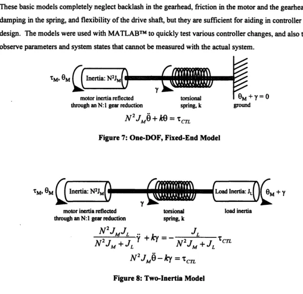
Very basic mathematical models of the test apparatus were developed to provide an even more simplified baseline for controller development. In the models, the apparatus was considered to be a rotating inertia connected to one end of a torsional spring through a thin, massless rod. The other end of the spring was rigidly connected either to ground in one model, or to another rotating inertia in the other model. A schematic diagram and the governing dynamic equations of each are shown in Figure 7 and Figure 8.
These basic models completely neglect backlash in the gearhead, friction in the motor and the gearhead, damping in the spring, and flexibility of the drive shaft, but they are sufficient for aiding in controller design. The models were used with MATLABTM to quickly test various controller changes, and also to observe parameters and system states that cannot be measured with the actual system.
TM, OM
+y=O
through an N:1 gear reduction spring, k ground
N
J
2+
kO
=
CTL,
Figure 7: One-DOF, Fixed-End Model
M,
OM
Inertia: N2JM Load Inertia:J
M
+ ymotor inertia reflected torsional load inertia
through an N:1 gear reduction spring, k
N
2JMJL
JL
9
+
ky
=
-N2JM +J
+
N2JM + JL :CTLN
2
JM
-ky =CTL
Figure 8: Two-Inertia Model
It was intended that controller analysis and design would first be performed with the one-DOF grounded model since it is much simpler to manipulate, and then additional fine tuning would be performed with the aid of the more realistic two-inertia model. However, the controller and gains derived with the simpler model performed quite well on the actual test stand even when the spring was free to rotate, so the two-inertia model was not used. But, if the need arises in the future, the analysis presented here can be repeated with the two-inertia model to perhaps build an even better control system.
5.2 Controller
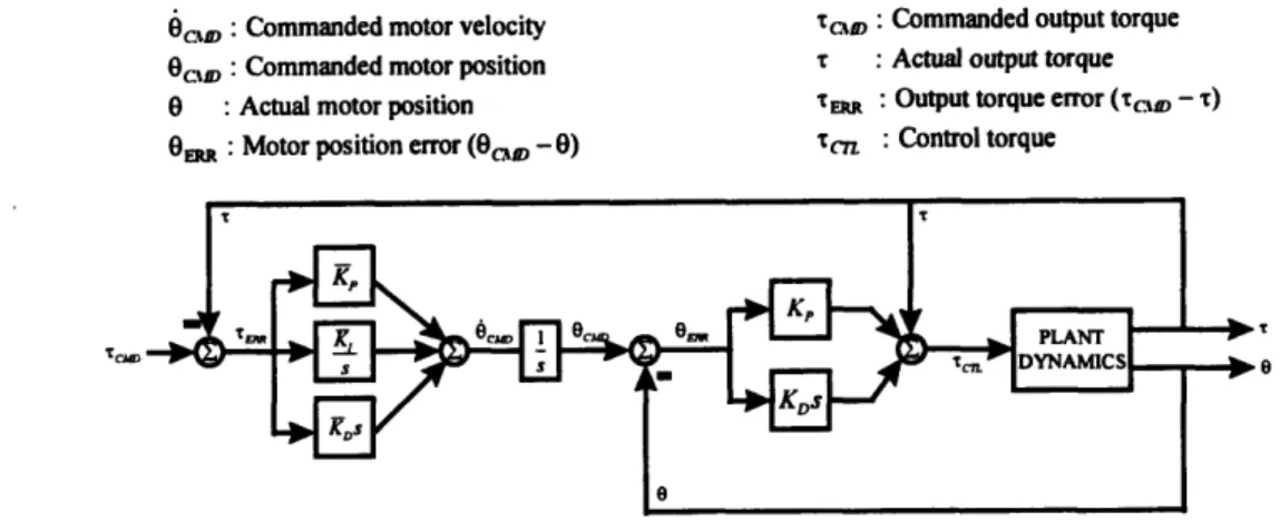
The control structure shown in Figure 9 was applied to the test system to implement force control of the
single joint. This type of algorithm, inspired by Salisbury [Salisbury, 1984], combines a stable, high gain, high bandwidth motor position control loop with a low gain, low bandwidth torque feedback loop. The inner position loop can achieve high bandwidth because there are no dynamics between the collocated
the torque feedback loop does not have a collocated sensor and actuator pair. In fact, all of the dynamics of this flexible system lie between the potentiometer and the motor. Furthermore, the potentiometer signal has a noisy derivative, which further limits the magnitude of the derivative gain.
OCs : Commanded motor velocity Trc : Commanded output torque O,, : Commanded motor position t : Actual output torque
0 : Actual motor position Tm : Output torque error (r,, -T)
On : Motor position error (O,, - 0) c7r :Control torque
Tcja
Figure 9: Controller Schematic Diagram
The branch of the feedback loop that adds the current output torque to the control torque is an attempt to remove some nonlinearity from the system. This can be seen by considering the fixed-end system model discussed in Chapter 5.1:
dynamic equation of motion:
N
2 JM +kO
= cTLbut, the control torque is: TCr = kO + K,(Ocxm -
)
+ K,(cMD - )so that the nonlinear kG terms cancel: N2JM +k = kO+K(0cM -0)+ KD(6cD -6)
leaving a seemingly linear equation N2JM ERR + KDOERR + KO ERI = 0
It appears that the result is a linear equation with equilibrium at the current operating point of the spring, about which the spring is linear to leading order. But, OCM and 6cuA are functions of the nonlinear stiffness, so the equation is still nonlinear, although some nonlinearity has been removed.
The transfer function from torque command to torque output, shown in Equation 2, was computed using the fixed-end model discussed in Chapter 5.1. It is important to note that the transfer function actually changes with the position of the spring, since the stiffness k is variable. However, Equation 2 is valid for small motions about a particular spring position, and is instantaneously valid when large motions are considered.
H(s)
(KK + K, K, )s2 + k(KDKK +
K,+Kp)s+kKK,
n(s)
-r
N
2
JS4
4+ (KD
+kKDK,D)s
3+(K, +kKDK, +kKpKD)
2+k(KDK
+KK,)s+kKpK,
Equation 2: Torque Command to Output Transfer Function
5.2.1 Loop Stability
Since no integrators are used on the inner position control loop, stability of that loop is guaranteed for any reasonable choice of PD gains. Strictly speaking, an ideal mass-spring-damper system with a PD controller
is always stable regardless of controller gains since energy is always being removed from the system [Slotine, 1990]. However, the real system is not ideal. Rather, it is subject to actuator saturation limits and phase lag in computing the filtered sensor derivative, which can induce instability if the gains are made exceedingly high.
In the outer torque feedback loop, the use of integrators is unavoidable. In fact, two integrators are required, one to overcome state errors caused by gearhead friction and the other to eliminate steady-state errors in response to ramp changes in the spring position. These integrators are a source of instability to the system and represent an additional limitation on the controller gains and bandwidth. The first integrator converts the commanded motor velocity to a commanded motor position and is needed because the substantial gearhead friction (-20mNm) can prevent the motor from moving when small velocities are commanded. If this were to occur, the motor position command and error would ramp, due to the
integrator, until the PD control torque is larger than the break-out friction. This integrator could have been added to the inner loop instead, making it a PID velocity controller. However, this would adversely affect the stability and bandwidth of the inner loop.
The second integrator is part of the outer PID torque feedback loop and contributes a component of the commanded motor velocity based on the torque error. It is needed to create a controller of high enough order to be able to produce the required spring deflection when the output side of the spring is moving, which occurs in the three-axis system whenever finger motion is desired. When this happens, the motor must be able to track the output position of the spring just to keep the spring deflection constant. Additional motor motions must then be superimposed to modulate the spring deflection based on the commanded output torque. The integrator successfully removes the steady-state torque error that would normally result in response to a unit ramp movement (i.e. constant unit velocity) at the output side of the spring. Although the actual fingers will not be limited to constant velocity movements, the higher order controller is better suited for handling more complex motions.
5.2.2 Filters
Digital filters were implemented in software to reduce noise from the sensor output signals and their derivatives, which were computed in software by back-differencing. The fourth order low-pass filters were created by cascading two minimum phase, critically-damped second order systems, and implemented with a Direct Form II Transposed structure. The cutoff frequencies were selected by carefully balancing noise attenuation (low cutoff) with minimal time delay (high cutoff).
Adequate noise attenuation was achieved on all sensor signals except the potentiometer derivative. The encoder output signal was extremely clean and did not require any filtering other than that intrinsic to the encoder reading chips on the SensAble Technologies PC Interface Card. The encoder derivative and the potentiometer position signals needed only high bandwidth (1000 Hz and 400 Hz, respectively), low time delay filters which were easily implemented. But, the potentiometer derivative signal was extremely noisy and required a very low bandwidth filter that could not be implemented without introducing time delay instabilities to the control loop. Instead, a moderate bandwidth filter (150 Hz) was selected. This filter maintained stability while moderately reducing the noise, but the derivative gain of the outer control loop was severely limited.
The noise on the potentiometer derivative signal was mainly due to A/D board fluctuations of +/- 1 bit in reading the pot output. This 1 bit fluctuation, which is the rated accuracy of the ComputerBoards
CIO-DASO8 board, causes enormous noise when back-differencing to compute the derivative. Several failed
attempts were made to solve this problem, including filtering with analog circuits, using a better A/D board, and ignoring the least significant bit (LSB) of the A/D conversion. Active analog differentiators and low-pass filters were created using op amps, resistors, and capacitors. However, the output of these circuits was contaminated by ambient 60 Hz noise, which could not be filtered without introducing excessive time delay. Furthermore, a higher performance A/D board (Data Translation DT3 1EZ) was tried, but the 1 bit fluctuation persisted and the signal quality did not improve. Finally, the LSB of the A/D conversion was dropped. But that too did not significantly improve signal quality, because a 1-bit fluctuation can affect more than just the LSB. For example, the difference between 3 (011) and 4 (100) is only 1 bit but changes all 3 bits. The best solution would be to replace the potentiometers with digital encoders so that A/D conversion is not necessary at all and the noise associated with analog signals is eliminated.
5.2.3 Selection of Time-Varying Gains
The selection of time-varying controller gains was performed by using the fixed-end dynamics model and the torque input/output transfer function (Equation 2) to choose a desired closed-loop bandwidth for both the inner and outer control loops. However, the transfer function is only instantaneously applicable
because of the changing spring stiffness. For this reason, the controller gains selected in this way are also instantaneously applicable, and vary as a functions of the spring stiffness, so that the bandwidth remains fixed for any spring position. As discussed earlier, high bandwidth was chosen for the inner, collocated control loop, and lower bandwidth for the outer loop.
The denominator of the torque transfer function was manipulated and analyzed to determine the relationship between the gains and the bandwidth of the individual control loops, so that particular controller gains that achieve the desired bandwidth could be computed. The denominator is shown here:
N
2jMS4+(KD + kKDKD)S
3+(Kp + kKDK,
+ kKPK
D)s
2+ k(KDK,
+ K,pK)s
+
kKpK
This denominator was then written as the product of the following two terms:
(
KD
K,
kKDKs +k(KK,
+K,K,)s
2+k(KK,
+KpK)s +
kKK,
N
JM
N2JM N2 Ms2 + KDs + K,
The first term represents the inner velocity loop, and is a simple second order oscillator whose parameters can be chosen to yield a critically damped system with the desired bandwidth. Equation 3 explicitly states the relationship between the inner loop gains and the corresponding bandwidth.
K,
= N2JM C,IERKD
=2N
JMKp
Equation 3: Inner Loop Controller Gains as a Function of Bandwidth
The second term represents the outer torque control loop, and was expanded via long division to be a second order system with two remainder terms:
kKD
K
k
KD2
K
2 + DKD S+ (KDK + KK D )+ kK K - 2KDKDKP KZK, KKD)s k(K KKD KDKPKP KPKDKD N2JM N2J M N MJ N2JM N2JM + N4J N2JMS2 + KDS+ K N2 JMs2 + KDS+KPBy setting each of these terms to an appropriate value, the bandwidth can be arbitrarily set. However, that