HAL Id: in2p3-00665624
http://hal.in2p3.fr/in2p3-00665624
Submitted on 2 Feb 2012
HAL is a multi-disciplinary open access
archive for the deposit and dissemination of
sci-entific research documents, whether they are
pub-lished or not. The documents may come from
teaching and research institutions in France or
abroad, or from public or private research centers.
L’archive ouverte pluridisciplinaire HAL, est
destinée au dépôt et à la diffusion de documents
scientifiques de niveau recherche, publiés ou non,
émanant des établissements d’enseignement et de
recherche français ou étrangers, des laboratoires
publics ou privés.
Status of the new high intensity injection system for
GANIL
C. Ricaud, P. Attal, E. Baron, J. Bony, M.P. Bourgarel, B. Bru, A. Chabert,
S. Chel, F. Daudin, M. Ozille, et al.
To cite this version:
C. Ricaud, P. Attal, E. Baron, J. Bony, M.P. Bourgarel, et al.. Status of the new high intensity
injection system for GANIL. EPAC 90 - Second European Particle Accelerator Conference, Jun 1990,
Nice, France. pp.1252-1254, 1990. �in2p3-00665624�
1252
STATUS OF THE NEW HIGH INTENSITY INJECTION SYSTEM FOR GANIL Ch. Ricaud, P. Attal, E. Baron, J. Bony, M.P. Bourgarel, B. Bru, A. Chabert,
S. Chel(t),F. Daudin, M. Ozille, P. Sortais , R. Vienet@) GANIL - B.P. 5027 - F-14021 CAEN CEDEX
Abstract : The design and construction of a new high intensity injection system at GANIL is under way ; the goals are to accelerate several tens of electrical microamperes of Ar and Kr ions (mainly to produce exotic nuclei) and to increase the heaviest ion beam intensities (Pb, U) . A factor of 2 to 3 will be obtained by raising the ECRIS frequency 10 to 14.5 GHz and another factor of 2 is expected from the new design of the axial injection line of one of the IWO compact cyclotrons (the capture of 40% of the beam in a 2 6” phase width is foreseen). A description is given of the source and its associated elements installed on a 100 k\’ insulated platfoml, along with the axial injection line and the central geometry of the injector cyclotron.
Introduction
The goal of the accelerator modification which has been already reported (I. 2’ is not only to widen the energy and ion ranges of GANIL, taking advantage of the higher charge states of the ECR sources, but also to increase the intensities and to have the arrangement of a very high intensity version suited in particular to exotic beam experiments.
So the modification is a two-stage operation :
- Stage I (called O.A.E.), achieved in July 1989, aimed to accelerate heavy ions (Ca7+, Xel8+, Ta22+, PV3+, U*S+) with the new 2.5 stripping ratio, at their maximum energy. Due to the very good qualities of the beams delivered by the CAPRICE source (emittance and currents) and to the reduction of the longitudinal space charge effect (by the use of the K.F. harmonic number 3 instead of 4 and slight injection energy increase on the injector cyclotron), currents have been multiplied by 5 to 10 (3): 70 cpA Ar7+ can be injected with 14 epA at the ejection, and we are now obliged to limit them (on gaseous ions, from carbon to xenon) to avoid damages in the machine beyond the injector. Routine values are presented at this conference (3).
- Stage 2 (called O.A.I.) is designed for the high intensities. In fact, this operation includes two phases:
a) The first one which is presented in this paper is to obtain a very high efficiency injection system c5! By increasing the injection energy to 100 kV, space charge effects become easier to control due to the velocity and the bunch length increases. In addition, taking into account the 6 dimensional phase space including space charge effects and the different couplings between phase planes, the new injection system wilt have a better transmission efficiency (about from 6.5% for small currents to 30% for 300 epA AP+ in the beam line). This new line is associated to the second injector and to a new 14.5 GHz ECR source : a factor of 3 to 5 is expected from the operation.
b) The second aspect not yet elaborated concerns the matching of the other parts of the machine to this current increase, in particular the stripping foil and diagnostics to control the beam losses.
So, in a first step, the efficiency improvement of the new injection line will be mainly convenient for the heaviest ions (Pb, U) for which the currents are smaller and the stripper efficiency drops down (6).
(1) - L’Orme des Merisiers, 91 I91 GiVYvette Cedex, France (2) - Labotatoire National Satume, 9 I I9 I GiGYvette Cedex, France
The t4.5GHz ECR Ion SOS
The source (ECR3) in operation on the first injector is a CAPRICE 2w~~, 10 GIlz identical to the source designed by B. Jacquot in R. Getter’s laboratory. Its very good performances allow to accelerate the heaviest ions Xe18+. Pb23*, LJzs+ as described in this conference (4). But for increasing the currents on the second injector devoted to the O.A.I., it has been decided to design and to build an other ECR sonrcc, called ECR4 (7)% founded on the following topics :
- to increase the frequency to 14.5 GHz, that gives a global shift toward the high charge states and a factor of 2 to 3 on the currents of the useful charges.
- to realize the best confinement with a 1T FeNdB hexapote and to keep the mirror inside the hexapole,
- to reach twice the value of the resonant field (O.Sz/t.O4 T) in the injection zone as for CAPRICE and to have the minimum value on the wall chamber located near the extraction zone,
- to keep the coil power less than 45 kW.
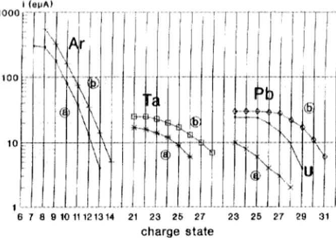
Figure I shows the results of ECR4 (curve h and ref. 8) obtained on the test bench (at I5 kV), that we can compare to these of our ECR3 basic reference (curve a) : the extracted current ratio is proportional to F and the charge state distribution is shifted.
For example : 5 e&A Ar14+, 30 CPA Pb*s+ and I2 ~+JA IJ27. are achieved.
Tests began 3 mon!hs ago, and thr source- is rcndj, to bc settled on the platform.
I / !
I ’
i I
I! --
PG
72
II-:
I
6 7 8 01011121314 21 23 25 27 charge state I -i 23 26 27 29 31Fiwre I : Charge state distribution of the ECR4 (14.5 Gliz) The 100 kV extraction optics
The beam coming out of the ion source is extracted and accelerated through a d.c., 4 electrode column providing directly the required injection energy (50 to 100 kV range) ; it is subsequently focused at the image position of the analyzing magnet by an Einzel tens (figure 2).
The electrode geometry and the applied voltages are determined by the FOCA code which uses an analytical potential distribution and linear space charge forces. This potential distribution is confirmed with POISSON and then SOS0 is used : this multiparticle, multicharge code accepts any kind of distribution in the transverse phase planes and therefore permits to take into account non linear space charge forces.
1253 None of these two programs can simulate the source-to-
puller interval ; as a consequence, the initial conditions are taken on the - 20 kV (with respect to the source) equipotential plane placed at the entrance of the first electrode : measurements of the test bench gave an emittance of 80nmm-mrad in both planes at 20 kV hnax = 3 mm, Q, = 16.7 mrad’mm).
mm! fkV
Fisrure 2 : Ion source extraction and acceleration
An example of result (Are+, 3 mA, 100 kV) is given on figure 2 which displays the voltage pattern and the beam size in one of the transverse dimensions (x) versus the abcissa z. It also shows the corresponding projection xx’ at the virtual object point : the non- linearities, essentially due to space charge forces, appear clearly and give and additional contribution of 26% to the emittance ; in fact, most of the particles are within a smaller, slightly tilted emittance. The Einzel lens allows keeping the focal length constant independently of the beam intensity.
Iniector cvclotron (CO]) : central region and matching conditions
The modification of the two injector cyclotrons has been previously reported at Berlin (3). The first one is in operation (with an efficiency of 20 to 25%) with the CAPRICE source and the 23 kV injection line. The second one is being modified in a similar manner, except for the central region which is designed for the new
100 kV injection energy and which is presented on figure 3.
The positions of the three first gaps with “posts” are adjusted to obtain a well centered my and to select in the (r, t’, $, AW/W) phase space, the particles with the smallest motion of orbit centers and the proper energy at the last (24th) turn.
This internal beam dynamics (9) allows to determine the matching conditions in the six dimensionnal phase space just before the first gap : taking into account the ECR emittance. we showed
that, ifwe have the following initial values :
sr = sv = 607r mm-mrad
r,,=2mm r’,,=30mrad r2l =0
z,,,,=6mm z’~~ = 10.4 mrad r43 = - .287 e max =1:6” Cr,$=3.3mradP
The beam characteristics obtained at the last turn will be :
sr = 26x mm-mrad Ed = IOxmm-mrad
AW/‘W = i 4. IO-3 A@=*60
The greet difference with the first injector (and classical axial injection lines) is the now, the beam line can take in charge the correlation (I’, 4). and can also bunch the particles in a * 6” phase extension with a larger efficiency (as explained in the following par.), so that the injector transmission becomes unity.
Inflector
A spiral-type inflector was chosen and already described(s) Its original height has been a little reduced, and its parameters are :
Maximum accelerating voltage Injection radius in the cyclotron Inflector height
Gap width (inlet/outlet)
Length of the reference trajectory MaXmum voltage between electrodes Maximum electric field in the gap
100
77.2 mm 105 mm_I
15/l 1.45 mm I65 mm 28.57 kV 19/25 kV/cm Slant of the inflector edge at exit(with respect to the median plane) 40.2 degrees Electrostatic auadmnole
Between the inflector and the gap, figure 3 shows the small electrostatic quadmpole (5) which realizes in particular the vertical matching to the injector. and allows to have a better filling of the inflector acceptance and to keep reasonable beam dimensions through the yoke hole.
y---h\
In,,
?,
/ /’
I
OUADRUPOLE
Firmre 3 : Central region for the 100 kV injection Beam line
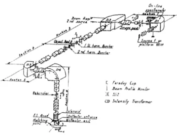
The beam line between the 100 kV insulated platform and the injector cyclotron is composed of five sections (figure 4). the optical functions of which can be divided in two main parts.
The first part includes sections 1 and 3 which allow respectively to select one charge state and one mass (resolving power = I part in 250 for a 100 nmm-mrad beam emittance) and to homothetically match the beam to a transversal focus point (point O), which is also the object for the second part. Thus, the tuning of the second part of the beam line is independent of that of the first part. The possibility is reserved to install an additional platform and a section 2, in a symmetrical position with respect to section 3.
The second part matches the beam to the injection point inside the cyclotron. It includes three sections with the following optical functions :
Section 4 : Transverse betatron matching Section 5 : Horizontal chromatic matching
Section 6 : Vertical chromatic and correlation between horizontal and vertical planes matchings The optical functions of this last section are necessary snecially to control the couplings introduced by the spiral inflectoJ5).
This Dart of the beam line allows the matching in the 6D phase space under the condition that the beam has a time structure before going through the chromatic sections 5 and 6.
1254
c Fd.+v cup j E..m PlrLh Aloo& !C J,‘,t
w Mana~ G*nr~~lnv
Figure 4 : Geneml lay-out ofthc beam line
The beam extracted from the source having no time structure, a double drift two harmonic buncher is placed on both sides of point 0. The drift between the harmonic 1 and 2 electrodes was optimized to obtain the largest efficiency in the phase acceptance of the cyclotron. Thus, for example, a 60% efficiency can be expected for a 50 to 60 epA source intensity (the reference beam being 15 keV/A Ati+).
For higher intensities (200 to 300 evA), a space has been saved in section 6 to insert a rebuncher in order to keep the transmission efficiency in the 30 to 40% range.
The optical study of the beam line has been achieved with Ihe GALOPR code’ 10). Figure 5 shows the beam envelopes in the c‘ase of a chromatic matching.
i. 3 1. PX YEI H3 0, PT CL V,PT 5l!iwTr P coi I+.--B:kY bid m-r-3 68186111 li.29 86
In-i: 18. En-,= ‘8 n m-a3 4d i ..a ,‘i ? / .!j I ii- .Qlmh.r , DI),ar,‘m ~IPr.rT.- ..:- ~ - s7’3-xa .--5-5~-‘c
18.j i’ i -;j-5 To----‘ iby:-- RBCISSL n
Figure 5 : Beam envelopes
Buocher
The double drift two harmonic buncher is made of two elements separated by 1.060 mm, each of them consisting in a 2 gap, cylindrical structure, 30 mm diameter. The first one, operating on the injector RF frequency is 80 mm long (@~/2) while the second is operated on the 2nd harmonic (length : DA/~).
The goal is to bunch a maximum number of ions inside a * 7.5” RF phase width in the middle of the first accelerating gap of the injector, located 9530mm downstream the middle of the lirat element. The initial radial emittance was chosen to be 60 mnm-mrad with a correlation coefficient of - 1.15 mrad/mm and a * 10.3 mm maximum envelope in the two transverse phase planes xx’ and yy’. The energy spread for the d.c. beam is + 10-5,
Figure 6 : 13unched beam in the A@. Ai+‘/% phase plane
The voltage distribution inside the elements was computed with our 3D program QES3D, so that the components of the electric fields could be directly injected in the ray-tracing program SOSOBU, a simpliiied version of SOS0 which includes time- varing fields but neglects all space-charge forces. When the position of the 2 elements is frozen (predetermined using the GALOPR code), only 3 parameters can be acted on to optimize the process, namely the values of the peak voltages V1 and V2, and the phase difference between harmonics 1 and 2. The result of such an optimization is shown on figure 6 in the Acp, AWN phase plane; 69?b of the particles are bunched inside the required phase interval, acquiring a maximum energy spread of * 1.2%.
In addition, the transit time factors of the elements are determined from the outputs of SOSOBU.
References
(1) - J. Fermi -“Project “O.A.E.” at GANIL”, in Proceedings of the 1 lth. Int. Conf. on cyclotrons - Tokyo (I 986) pp.24-30. (2) - E. Baron, R. Beck, M.P. Bourgarel, B. Bru. A. Chabert,
Ch. Ricaud -“High intensity and space charge problems at GANIL”, in Proceedings of the 1 lth Int. Conf. on cyclotrons - Tokyo (1986) pp. 234-237
(3) - M.P. Bourgarel, E. Baron, P. Attal -“Modification of the GANIL injectors” in Proceedings of the 12th Int. Conf. on cyclotrons - Berlin (1989)
(4) - GANIL Group (presented by L. Bex) - “GANIL Status Report” - This conference
(5) - Ch. Ricaud, P. Attal, E. Baron, R. Beck, J. Bony, M.P. Bourgarel, B. BN, A. Chabert, S. Chel, R. Vienet “Preliminary design of a new high intensity injection system
for GANIL” in Proceedinas of Ihe 12th. Int. Conf. on cyclotrons - Berlin (1989)-
(6) - E. Baron. Ch. Ricaud - GANIL int. retort no20 (1990) if) - P. Sorta& P. Attal, M. Bisch, M.P. gourgarel,
P. Leherissier, J.Y. Pacquet - ECRIS Development at GANIL - Proceedings of the Int. Conf. on Ion Sources
Berkeley July lo-14 (1989) pp. 288-290
(8) - if.P. Bourgarel, P. Sortais, M. Bisch, P. Lehirissier: J.Y. Pacquet, J.P. Rataud - GANIL int. report no22 (1990) (9) - M.P. Bourgarel - GANIL int. report no2 1 (1990)
(I 0) - B. Btu, “GALOPR, a beam transport program, with space charge and bunching, presented at the 3rd Int. Conf. on Charged Particle Optics, Toulouse April 24-27, (1990)