Direct Haptic Control of a 3-Axis Milling Machine
by
Edmund W. Golaski
S.B., Mechanical Engineering
Massachusetts Institute of Technology, 1999
Submitted to the Department of Mechanical Engineering
in partial fulfillment of the requirements for the degree of
Master of Science in Mechanical Engineering
at the
MASSACHUSETTS INSTITUTE OF TECHNOLOGY
June 2001
@
Massachusetts Institute of Technology 2001. All rights reserved.
A uthor ...
Department of Mechanical Engineering
May 23, 2001
Certified by...
Sanjay E. Sarma
Associate Professor
Thesis Supervisor
Accepted by...
BRKER
Ain A. Sonin
Chairman, Department Committee on Graduate Students
MASSACHUSETTS INSTITUTE OF TECHNOLOGY
Direct Haptic Control of a 3-Axis Milling Machine
by
Edmund W. Golaski
Submitted to the Department of Mechanical Engineering on May 23, 2001, in partial fulfillment of the
requirements for the degree of
Master of Science in Mechanical Engineering
Abstract
A haptic device has been connected to a small 3-axis milling machine actuated with
stepper motors. The interface is regulated by speed-limit and collision-detection algorithms which give the user enhanced manual control of the mill. Force feedback, based on the concept of a stiff spring connecting the haptic input to the mill, makes the control of the mill more intuitive. The machine drives are open loop, so the system models the machine tool, and only sends commands it is confident the machine can execute.
The test hardware assembled for this thesis serves as a platform for exploring the "virtual tool" model of direct manual machine control. Applications of the technology include improved efficiency of manual control of large machining centers, a 3-D stencil for machining, intuitive feel of cutting force and machine kinematics models, and teleoperation.
Thesis Supervisor: Sanjay E. Sarma Title: Associate Professor
Acknowledgments
I would like to start by thanking those who have made my 6 years at MIT so
worth-while. Thanks to Tree Raine, Heather Dunn, and Liz Greig for the coffee, advice, and friendship. Thanks to the casts and crews of Company, Cabaret, and The Reception for joy and satisfaction beyond description. Thanks also to Toscannini's, Thomas H. Adams, Jamez and Jax Kirtley, John Van der Meer, Erin Lavik, Steph Sharo, Kristin Jugenheimer, Gisele Proulx, Jen Owens, Amanda Johnsen, Robin Ivester, Mark Rousculp, Allison Clayton, Stan Zanarotti, Jeremy Brown, Nick Ingolia, Jake Harris, Joe Foley, Astrid Richter Allen, Rosendo Fuquen, and James Kretchmar.
Stephen Ho provided insight and guidance at all stages of this work. Mahadevan Balasubramaniam made key suggestions, and helped me out when I was stuck. Elmer Lee introduced me to the lab and to Sanjay by hiring me as an undergraduate, and ever since has served as a mentor and friend. Adachi Yoshitaka developed the haptic device that was so critical to this project. Nick Martin worked his magic to make the machine move. I cannot thank them enough. In addition, Seung-Kil Son, Ceani Guevara, Yogesh Joshi, Niranjan Kundapur, Krishnan Sriram, Winston Fan, David Rodriguera and Paula Valdivia y Alvarado made the lab a great place to do graduate work. Thanks also to Gerry Wentworth, Mark Belanger, Fred Cote, Dave Dow, and Bob Kane of the LMP machine shop. Professors Samir Nayfeh, Igor Paul, Alex
Slocum, Woodie Flowers, and Ernesto Blanco taught me to be an engineer, and to
enjoy doing it. Arthur Ganson showed me that there can be engineering in art. Finally, I would like to thank my advisor, Sanjay Sarma, for his guidance, mentor-ing, and patience, and my family: Mom, Dad, Grandma, Alexandra, and John Paul, for, well, everything.
Contents
1 Introduction 15
1.1 Motivations for enhanced manual control . . . . 16
1.2 Overview of the project . . . . 17
1.2.1 H ardw are . . . . 18
1.2.2 Softw are . . . . 19
2 Related Work 21 3 Core Intellectual Models : The Virtual Tool 25 3.1 V irtual Tool . . . . 25
3.2 Alternative models . . . . 26
3.2.1 Machine-in-the-loop . . . . 26
3.2.2 L ag . . . . 27
3.2.3 Stiff Spring . . . . 28
3.3 Implications of the Virtual Tool and Stiff Spring Model . . . . 28
3.3.1 Open Loops . . . . 29
3.3.2 A Haptic With a Sense of History . . . . 29
4 The Machine as Output Device 31 4.1 H ardw are . . . . 31
4.2 Softw are . . . . 33
5 The System 35 5.1 O verview . . . . 35
5.2 Program Core . . . . 5.3 Virtual Tool, State Variables, and Common Memory . . . .
5.4 Haptic Loop . . . .
5.5 Graphics Loop . . . .
5.6 Analysis Loop . . . . 5.7 Collision . . . . 5.7.1 Overview . . . . 5.7.2 Sticking vs. Sliding: Collision Remediation and Other
5.8 Speed Limits . . . .
6 Results
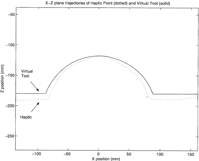
6.1 Haptic and Virtual Tool Trajectories
6.2 Sticking vs. Sliding . . . .
6.3 Low-Pass Filtering Effect . . . . 6.4 Observations. . . . .
7 Conclusions
7.1 Observations and Lessons Learned .
7.2 Conclusions . . . . 8 Future Work 8.1 Introduction . . . . 8.2 Simple Extensions . . . . 8.2.1 5-DOF . . . . 8.2.2 Collision Detection . . . . 8.2.3 3-D Stencil . . . .
8.2.4 Servos instead of Steppers . . 8.3 Looking Further . . . .
8.3.1 Feeling Tool Forces . . . .
8.3.2 Speed Limits . . . . 8.4 New Applications . . . . Phrases 35 37 38 39 40 40 40 41 43 45 45 45 47 48 51 51 51 53 53 53 53 53 54 54 55 55 56 57 . . . . . . . .
A Software Engineering for Mechanical Engineers
B Collision Remediation Example 61
B.1 The Ball-Sphere-Plane Algorithm ... 61
B.2 The Flat End Mill Algorithm ... ... 62
B.3 Caveats .... ... ... ... ... 63
List of Figures
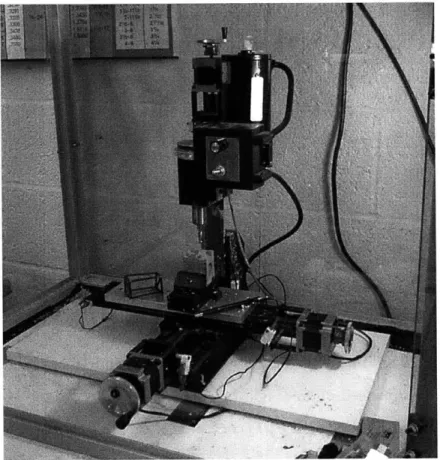
4-1 Sherline 3-Axis mill with stepper motors, with ball point pen for scale. At left is a box which is 25mm x 25 mm x 50 mm to show the size of
the scaled workspace . . . . 32
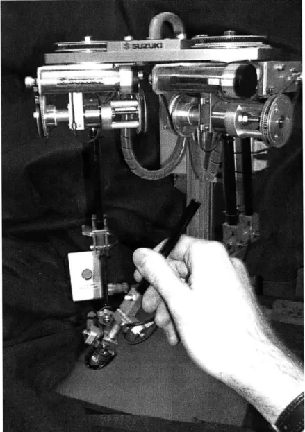
4-2 Suzuki 5-DOF Haptic Device . . . . 34
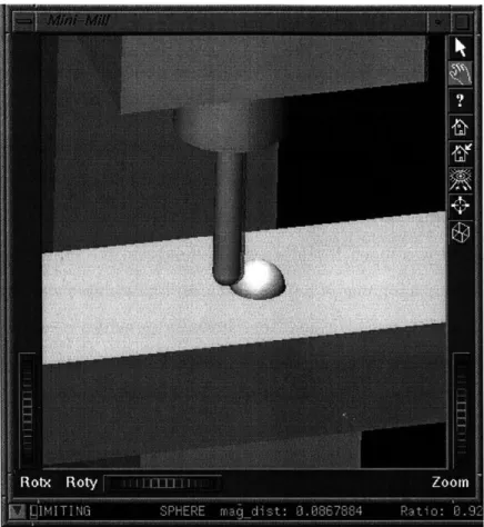
5-1 Screen-shot of graphical display. Speed-limits and collision remediation are active. Ghost tool is displaced to the right . . . . 39
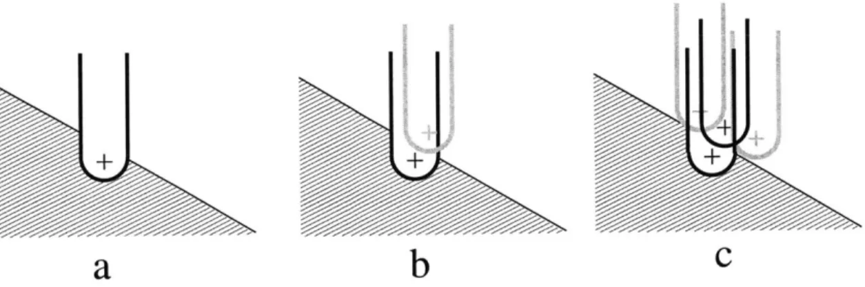
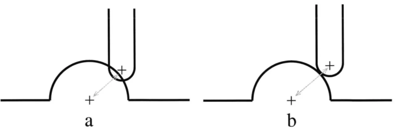
5-2 Collision Remediation. (a) the tool penetrates the object. (b) the tool is decollided (c) for a binary collision detection algorithm, the optimal position (black) which minimizes distance is selected over alternatives (gray ) . . . . 42
6-1 Ball End Mill Tracing a Spherical Bump . . . . 46
6-2 The filtering effect of different sampling rates . . . . 47
6-3 Spherical bumps cut in Ren-Shape plastic . . . . 48
B-1 Ball-Sphere-Plane Algorithm (a) tool colliding with sphere (b) decol-lided position . . . . 62
List of Tables
Chapter 1
Introduction
Haptic systems are a growing area of research. New fast algorithms for detecting and avoiding collision offer new possibilities for real-time simulation of real environments. On the other hand, manual control of machine tools is not an active area of research.
CNC (computer numerical control), CAM (computer aided manufacturing), and other
more cutting-edge areas of interest have relegated manual control to a
operator-interface problem for industrial designers. Connecting a haptic device to a small
machine tool has created a new prototyping tool, shed new light on the haptic field,
and hinted at a new model for controlling machine tools.
Chapter 2 discusses related work which applies to this thesis. The project de-scribed here is very much a synthesis of a number of existing haptic technologies to
solve a new problem.
Chapter 3 describes the core intellectual models which govern this work. In
par-ticular, the virtual tool is discussed and compared to alternative representations. Chapter 4 discusses the machine tool which was used as an output device. A control package was assembled by Nick Martin (MIT SB '03).
Chapter 5 uses the software system as a framework to discuss the algorithms we designed and implemented. Implementation-specific details are included in some
places to highlight which choices were made because of hardware or time constraints,
versus which choices are believed to be optimal and thus ideal for future work.
of the system. We asked machinists, mechanical engineering students, and users with little or no machining experience to use the system and we made note of their reactions.
Chapter 7 attempts to draw conclusions based on the lessons learned from our research.
By contrast, chapter 8 lays out a vision for the future development of haptics as
a tool for controlling machines.
1.1
Motivations for enhanced manual control
Modern manufacturing equipment still requires human intervention. This is particu-larly true for machining centers. First, for small production runs, prototype parts, and tooling, there are times when it is simply more efficient and economical for the opera-tor to direct the machine tool by hand. Second, in a practical production environment not every eventuality has a corresponding CNC program - the skilled operator can intervene, and what might have brought the production system to a halt is now just a note to the production engineers to fix a detail in the next revision of CNC code. Set-up processes for machining centers in many plants also require the operator to drive the machine to certain locations manually. Examples of these include "touching off" the tool to qualify the tool length, and "taking a chip" to locate a new piece of stock.
Most machining centers have a jog dial on their control panel. The user selects which axis to control with the dial and then drives the machine manually in that direction by rotating the dial. The term "manual" here is not meant to suggest that the exertion of the operator is what provides the force to move the machine but rather that the dial sends command signals to the machine's actuators.
This arrangement has disadvantages. For example, only one axis can typically be driven at a time. There are times when the operator would benefit from being able to drive the machine in all of its degrees of freedom at once. Rapid moves from point to point are particularly ripe for improvement, as are small "clean-up" jobs, where
there is excess material in an irregular shape. An example of the latter is the removal of weldment beads from non-flat surfaces.
Another input device, more common on CNC coordinate measuring machines, is a rotational hand controller, or joystick. Vertical moves are commanded by the twisting of the stick around its major axis.
While the joystick solves the problem of commanding 3 axes at once, it does not scale well to 5. Moreover, the motion is not really natural. A joystick converts the displacement of the control input into a velocity output. By contrast, a haptic device converts a displacement input into a displacement output. The displacement-displacement input model is seen in computer interfaces as mice, track-balls, and track-pads.
In a way, computer numerical control (CNC) has created a layer, or disconnect, between the operator and the machine tool. The operator can no longer respond directly to the sound of chatter, the smell of overheated metal, or the feel of a tough material. Enhanced manual control brings the operator back into the loop, making use of the best aspects of human control (judgment and experience) and computer control (rapid calculation).
1.2
Overview of the project
The system developed is an interface between an existing haptic device and a small 3-axis machine tool. The user holds a grip which resembles a pencil. The haptic device reports its position in 5 degrees of freedom, and can accept commands to generate a force in each of three dimensions, and torque in two degrees of freedom around the grip. Torque around the major axis of the grip is not needed, because this is the machine spindle axis.
The system takes the position input from the haptic device, and uses it to drive a virtual tool. This virtual tool is a numerical representation of the machine's position. It is tightly coupled to the actual machine tool, by means discussed in more detail later. The input position is checked against speed-limiting and collision-detecting
algorithms. If the input position would violate collision constraints, or would require the machine to move faster than it can, a new position is selected, and the virtual tool is sent there. The user is given visual feedback from the actual machine and from a graphical representation of the tool and workspace. In addition, the system generates a force representing the direction and magnitude of the difference between the positions of the input device and the virtual tool. With this, the user can feel where the tool is relative to the input grip, as if a stiff spring connected the grip and the machine tool.
The collision detection results in a 3-D stencil, constraining the machine to only move within "acceptable" regions of space. The speed limits cause the model (the virtual tool) to behave like the real machine, but also confine the machine to accept-able regions of velocity space, the boundaries of which are determined by machine and controller performance as well as feed-rate limits.
1.2.1
Hardware
The milling machine used for our research is a small 3-axis Sherline mill. The axes are
guided and supported by dovetail joints, and the lead screws are driven by stepper motors. The machine was purchased with a CNC package from Flashcut CNC, but
most of the control system was bypassed with the stepper controller built for the
project by Nick Martin.
The haptic device was developed and built by the Suzuki Corporation for research conducted in this laboratory by Stephen Ho, Mahadevan Balasubramaniam, and
Kr-ishnan Sriram. The device accepts force information and reports the position of the
haptic grip.
The software that is the core of the project runs on a dual 250 MHz processor SGI Octane running the IRIX 6.5 operating system (IRIX is similar to UNIX, but
is a proprietary OS developed by SGI). The Octane was chosen for haptic
applica-tions because of its powerful graphics capabilities (core to haptic collision detection research) and its suitability for real-time applications.
1.2.2
Software
The software developed as part of this research consists of three process loops which share the positions of the haptic device and the virtual tool in common memory. The haptic loop runs very quickly (approximately 1000 Hz), reading the position of the haptic device and applying a force.
The analysis loop runs at the speed of the machine, and checks the input position against speed-limiting and collision-detecting algorithms. A position which does not violate speed or position constraints, and which most nearly approximates the position of the haptic input, is set as the virtual tool position. This position is accessed by the haptic and graphic loops, and is also sent to the machine controller.
The graphics loop runs at a visually acceptable graphics refresh rate (20-30 Hz) and provides an additional feedback channel. In addition to a graphical representation of the machine tool, the display conveys information to the user about whether the speed limiting or collision detecting limits are being invoked.
Chapter 2
Related Work
Thomas Massie revolutionized the haptic community with his low-cost PHANToM device [9]. While the PHANToM does not directly impact this thesis, it provided low cost haptic hardware which was used in many of the other works referenced here [2, 10, 15]. In addition, Massie spelled out many of the requirements of haptic devices, including the 1000 Hz update rate.
Margaret Minsky's [11] research dealt primarily with haptic simulation of texture, but in so doing she expanded several areas of haptic research. She also performed studies which found 1000 Hz to be a good haptic update frequency.
Mandayam Srinivasan and the MIT Touch Lab have done a lot of work on human factors associated with haptic devices. With their work on the the physical limita-tions of the human body and the psycho-physics of what the human can perceive they provide hard data for designers of haptic devices and simulations. Tan, Srinivasan, Eberman, and Cheng [13] studied the force and resolution limits of the human arm.
Wu, Basdogan, and Srinivasan [14] studied the interaction of visual and haptic cues,
with the conclusion that they are strongly coupled. Optical illusions caused by per-spective distortions can confound a haptic simulation. More importantly, graphical representations of good behavior can ameliorate some of the shortcomings of haptic displays, particularly when trying to simulate rigid objects.
Zilles and Salisbury [15] introduced the concept of the god-object. The god-object is a proxy for the haptic device that can be subjected to the physical constraints
of the system being modeled. The force response is then calculated based on the displacement between the god-object and the haptic point. In that way it is the forerunner of the virtual tool introduced in this thesis. The god-object solves some nagging problems of many haptic systems.
The first is snap-through for thin objects. If the user pushes hard enough on a thin virtual plate, soon the haptic point passes through the far surface, and is now outside the object. The god-object is not permitted to penetrate the surface, and so serves as a reminder on the near side of the plate.
This problem is exacerbated and extended by the common technique of superpo-sition of vector fields for force response. As the haptic point passes the midpoint of the plate, the nearest surface (often used to choose the direction of force) is on the far side of the plate. The haptic literally snaps through the object. In other situations (mainly obtuse concave plane intersections) the superposition of forces yields a force that is greater than it should be.
Mendoza and Laugier [10] developed a system with 1000 Hz haptic update rate and 10 Hz object update rate. Their motivation was to have deformable virtual objects, which they were apparently not capable of updating at the haptic update rate. Their method was to use a local topological model, which the haptic system interacted with at 1000 Hz and which was updated at 10 Hz.
Their work builds on that of Adachi et. al. [1] who introduced the idea of inter-mediate representations - the simplification of local geometry as a plane to allow for the required fast haptic update rate. Adachi reports results for plane update rates as low as 2.5 Hz and as high as 500 Hz (in each case, the haptic still servos to the intermediate plane at 1000 Hz). He showed first that the required plane update rate is a function of the velocity of the haptic point, and second that the tracing of a surface modeled with intermediate plane representation was aided significantly by the introduction of artificial friction. Without the friction, the collision avoidance algorithm results in a very slippery surface, which turns out to be difficult to follow. Zilles and Salisbury assume planes for their algorithm for locating the god-object on the surface of the virtual object. Thus, any extension of their work to the general
haptic case would be aided by Adachi's work.
Avizzano and Bergamasco [3] attempt to generalize the haptic interface to include not only interaction with virtual environments, but also telerobotic applications and trainers for instruction or rehabilitation. Their goal is a generalized "reactive" model which surmises intent and conditions the force feedback appropriately. An example of this would be a system which determines the task the user is trying to accomplish and applies corrective forces to keep the user on the path appropriate to the task. The degree of path-constraint depends on the situation. Their key idea is that of generating only the forces appropriate in the context of a given situation. The pri-mary limitation of their paper is a lack of real examples. They propose a general
architecture, with no hints as to how to implement it.
Sheridan [12] introduced the concept of Afferent and Efferent channels. Afferent channels convey information (be it force, position, or other) from the system to the user. Efferent channels convey information from the user to the system. Avizzano and Bergamasco further split each of these into an active and reactive level, generalizing from the requirement of a passive system to the possibility of an active haptic system. Historically, the passivity requirement has been motivated by stability concerns. The grip of the operator (firm or loose) is variable, and makes the control problem difficult. Adams and Hannaford [2] propose a "virtual coupling" which can be de-signed to be stable, given a passive operator and virtual environment. Theirs is a generalization of the virtual coupling network to include impedance (a force is calcu-lated from a position input - PHANToM, Suzuki haptics), or admittance (position or velocity calculated from a force input - the Iowa State/Boeing virtual aircraft control column [5]). Of particular interest is their observation that impedance based haptics
tend toward instability with a loose user grip, and admittance based haptics with a firm user grip.
Another approach to stability is to simply require the haptic system to be passive, using methods suggested by Colgate and Schenkel [6]. Often, these systems boil down to requiring that the net energy of the haptic interface is decreasing, which can be achieved through damping. The advantage of the virtual coupling is that the stability
control can be implemented at that level rather than at the virtual environment level (still, Adams and Hannaford, assume that the virtual environment and the user are passive).
Chapter 3
Core Intellectual Models : The
Virtual Tool
This chapter discusses the development of the core model for the system. This model governs the mathematical relationships between the haptic device and the machine tool. It is the essence of the research work.
3.1
Virtual Tool
The virtual tool concept evolved slowly over the course of exploration discussed below. However, because it is an important concept, it is worth discussing here, in its own section. The virtual tool is conceptually similar to Zilles' "god-object"
[15]
or the "virtual coupling" [2], but evolved from a different thought process and solves a different problem. God-objects and virtual couplings simplify the stability problem and solve problems like snap-through. The virtual tool springs from the fact that the system does not simply interact with a virtual environment, but commands a real machine with finite speed and acceleration limits. The virtual-tool is a proxy for the real machine, since the machine control loop is open. We will attempt to make the distinction, as well as the similarities, clear here.The virtual tool is a numerical representation of a real tool. It consists of the set of variables needed to completely describe the state of the real machine tool, which
is to say a position (in the three axis case) or a position and posture (in the 5-axis case). Its connection to the real tool is to be determined.
For the 3-axis system, the virtual tool is a three element vector representing X,
Y, and Z coordinates. A production system would contain other attributes: spindle
speed, spindle status (on/off), coolant status,etc.. The virtual tool may be said to contain all the state variables of the real machine, to the degree of detail required by the application.
The virtual tool links the haptic device to the machine in some way. There might be some maximum permissible lag between the virtual tool and the machine. The virtual tool might be driven by the machine, or might be driven by the input system. For a stepper-motor system without encoders, feedback of the actual machine position is impossible. Thus the machine is treated as an open loop device. The virtual tool then becomes the proxy for the machine.
The selected virtual tool model assumes that the machine reflects exactly (to within some error) the position of the virtual tool. This is achieved by constraining the virtual tool to only execute moves which the machine can execute in the same time interval, and only updating the virtual tool's position at a rate which permits the machine to follow. This tight but still open loop coupling between the virtual tool and the machine (on faith, if you prefer) is one of the cornerstones of our thesis. Mathematical bounds can easily be established for the conditions under which this assumption is valid.
In particular, the open loop insulates the system from the effects of time lag. All latency-critical elements are local.
3.2
Alternative models
3.2.1
Machine-in-the-loop
In this model, the haptic grip is made to reflect the position of the machine tool exactly. The haptic loop is designed as a control loop for which the machine position
is the reference input. The force required to keep the grip at the machine position (read as the current through the motors of the haptic) is the input to the system.
If the machine tool is free to move, then it will respond to the smallest force input,
and the user will not feel great resistance to moving the input grip. If, however, the system decides that the machine should not move into a particular region, or if the machine is moving at its maximum speed, then further coaxing will be felt as greater force. This is an admittance model, like the Iowa State/Boeing virtual aircraft control column [2, 5].
The advantage to this representation is that the position of the machine is exactly represented by the input grip. A very intuitive user experience comes from the simi-larity between this model and reality - we push on a quasi-rigid object, and it moves according to the force we apply and the forces applied by the environment. The hap-tic will not move faster than the limit speed or penetrate an object, no matter how hard we push.
The primary reason for rejecting this model is that this is not how the Suzuki hap-tic interface was designed to be used. The bulk of the literature deals with impedance models, so Suzuki are not alone in preferring impedance over admittance. Symmet-rically, control systems typically deal in displacements rather than forces.
In addition, keeping the machine in the loop eliminates the possibility of time lag between the system and the machine output, closing off the possibility of distant haptic teleoperation.
3.2.2
Lag
In this model, some displacement or "lag" is permitted between the haptic point and the machine tool. The direction of this lag is used to point the machine. Forces are applied if the displacement exceeds the allowable lag.
The stiff spring model below retains the advantages of this representation without the associated backlash. The stiff spring model (described next) was judged superior.
3.2.3 Stiff Spring
The force applied to the haptic grip is proportional to the displacement between the haptic point and the virtual tool. This restoring force gives the user an intuitive sense of where the machine is relative to the haptic grip.
This arrangement lends itself to simple implementation. The haptic loop (which must update at a rate of at least 1000 Hz) can simply compare the input position to the virtual tool position. Collision-detection and speed-limiting are done in a separate loop which updates the virtual tool. The speed of this loop need only be less than the update interval for the machine tool, which is likely to be substantially longer than 1 millisecond.
In searching for the "right" interval for the virtual tool to update, we need look no further than the work of Adachi et. al. [1]. Adachi found that the required update interval for intermediate representations (planes in his case, the virtual tool point in ours) was a function of the velocity of the haptic point. At too low a rate, Adachi's intermediate planes began to feel bumpy. In our system, a low virtual tool update rate corresponds to decidedly jumpy feel as the user senses each discrete update of the virtual tool. Our maximum velocity (which determines the minimum update rate) will be a function of the machine we are driving, or, rather, the speed limits we impose on it.
The simplicity and intuitive user experience generated by the virtual tool model made it the natural choice for our work.
3.3
Implications of the Virtual Tool and Stiff Spring
Model
The virtual tool and stiff spring models give rise to a number of interesting features. Here we describe a few of them.
3.3.1
Open Loops
The machine driving loop is essentially open. It could be closed with position feedback making sure the machine is actually at the virtual tool position, but it doesn't need to be. This separation creates an abstraction barrier between the two elements. The machine cannot threaten the stability of the haptic system.
More importantly, the model lends itself to telerobotic operations. Information cannot travel faster than 186,000 miles per second (the speed of light). A 1 millisecond round trip (servoing directly to the machine) limits range to less than 100 miles. A more realistic 10 millisecond machine update interval still permits only 1000 miles distance between haptic and machine output. If the time required for speed limiting or collision detection algorithms are included, the permitted distance drops considerably. The virtual tool is a local model of the remote machine, with potential applications to transcontinental or even interplanetary remote operations. True, the operator does not feel what the machine actually feels, he merely interacts with a simulation. How-ever, this simulation is haptic, and brings a level of intuition never before experienced in computer-abetted machine control.
3.3.2
A Haptic With a Sense of History
The virtual tool is maintained along with the haptic position in common memory. Collision algorithms have the virtual tool position available to them, and can use this like a god-object to eliminate haptic artifacts (like snap through of thin objects). With a sufficiently fast machine update interval, simply calling the speed limiting
algorithm twice, once before the collision remediation and once after, restricts the collision search to a small area around the virtual tool. This permits the use of very simple collision algorithms.
Chapter 4
The Machine as Output Device
This chapter describes briefly the hardware, software, and key concepts associated with the machine output device.
4.1
Hardware
The mill used is a Sherline 3-axis milling machine, shown in figure 4-1. The axes are anodized aluminum, with sliding dovetail bearings. Steel lead-screws turn in brass nuts. Travel is approximately 22 cm in the X direction, 12 cm in Y, and 16 cm in Z.
The spindle is 1/2 HP, with a top speed of 2800 RPM.
The machine shipped fitted with a Flashcut CNC control package, but this proved inadequate for direct control by the computer which runs the haptic system. Nick Martin put together an alternate control package using a stepper motor controller from The Motion Group.
Max Machine Speed (each axis) 1.4 mm/sec 3 in/min
Motor Resolution 640 Steps/mm 16,000 Steps/in
Backlash (X) 0.125 mm 0.005 in
Backlash (Y) 0.05 mm 0.002 in
Backlash (Z) 0.125 mm 0.005 in
Workspace (X x Y x Z) 50 x 25 x 25 mm 2 x I x I inch
Figure 4-1: Sherline 3-Axis mill with stepper motors, with ball point pen for scale. At left is a box which is 25mm x 25 mm x 50 mm to show the size of the scaled workspace
The performance of the system is shown in table 4.1, with the most significant features being a maximum speed of 1.4 mm per second (3 inches per minute) and a machine update rate of 30 Hz. It was found that at 3 inches per minute it was difficult to distinguish collision from speed limiting, so a scaling factor was introduced between machine-space and virtual-tool-space. The effect of this is to permit the haptic device to move at a rate which is comfortable for the user. The trade-off is that the working volume of the machine is that of the haptic device divided by the scaling factor. For our scaling factor of 10, this corresponds to a machine working volume of approximately 25 mm x 25 mm x 50 mm (shown at left in the figure).
Figure 4-2 shows the Suzuki 5-DOF haptic device. The device reports its position and posture in 5 degrees of freedom, and can apply forces and torques. The maximum force available (for safety reasons) is 5 newtons.
4.2
Software
Nick Martin's control package included a suite of C functions to send positions to the machine, and to initialize the machine. Conceptually, machine-space is synchro-nized absolutely to virtual-tool-space2. This eliminates the need to re-calibrate the graphics display relative to the machine tool. Haptic space need not be synchronized to machine space, in fact it is preferable to have some provision to allow the user to re-home the haptic device on the fly. This is analogous to picking a mouse off a table, moving it, and setting it down again, and would accommodate the individual ergonomics of users as well as the kinematic non-uniformities in the haptic workspace.
'Our scaling factor was empirically determined. In theory, a minimum value for the speed limit imposed on the haptic device could be calculated. This value would be a function of the minimum perceivable speed (from human factors research) and the stiffness of the coupling between the haptic device and the virtual tool (which is a function of the haptic controller)
2This can be achieved by homing the machine tool with limit switches, or by zeroing the controller
at a known machine reference position. Currently we use the latter method, as it simpler and faster for quick evaluation runs.
Chapter 5
The System
This chapter discusses the software package which implements our haptic machine control system. It is not intended to document the code, but rather to give the reader a sense of the algorithmic choices made and some of the interesting challenges associated with rapid haptic updates and real-time control of the machine tool.
5.1
Overview
The development task was split into several modules. A haptic module reads the haptic position and determines the forces to be applied by the haptic device. An analysis module determines the tool output position based on the input position subject to speed and position constraints. A graphics module gives the user additional visual feedback.
5.2
Program Core
The execution of the software forming the system can be thought of as operating in three phases: initialization, running, and cleanup. The running phase of the major modules discussed above lend themselves to representation as loops. Massie showed that the haptic loop must run at about 1000 Hz to create a realistic haptic experience
loop only needs to run at the rate that the machine tool can accept new input. Running the graphics loop faster than 20 - 30 Hz is unnecessary, because the eye
1
cannot distinguish frame rates faster than that under most circumstances
The very different rate requirements of the three looping modules suggest sepa-rating the loops and running them in parallel. Each loop can then run at its own preferred rate, efficiently allocating computational resources. Modern operating sys-tems lend themselves to multi-process programs, and the SGI IRIX operating system is particularly suited to real-time multi-process applications.
Real-Time as a programming concept refers to the reliability with which a process can run. Operating systems which are not Real-Time (Windows NT, for example) cannot guarantee that a process will run at any particular time, and require additional hardware buffers to run machines. Real-Time operating systems (many types of Unix, including IRIX) can control a machine directly, whereas non-real-time systems run the risk of the machine running out of control if another process happens to preempt the processor.
The command fork was used to spawn new processes from the original process. Each process then runs independently of the others, subject to processor availability. Care must be taken to ensure that critical processes are not overwhelmed by less critical but computationally more intensive processes. Tools are available to control the relative priority of various processes, and even to isolate a critical process on its own processor (a distinct advantage of a multi-processor system).
The independence of the different processes introduces the problem of sharing information between them. A common tool is the pipe - a way of pushing data through a conceptual pipeline. However, the data are generated and used at vastly different rates (we would be stuffing haptic positions into a pipe 1000 times a second and only drawing them out 100 times a second), so another method is needed.
Shared memory presents a better solution. Each process links to a common
mem-135 mm film runs at 24 frames per second. Video conforming to the North American/Japanese
NTSC standard runs at 30 frames per second. Some film-motion-rides, which feature very rapid
ory location, and can access it at its own rate. While more than one process may read a datum, only one process ever needs to write any given datum, so the problem of data corruption is avoided.
Timing of the various process loops is accomplished quite simply. We define a loop interval (the inverse of the loop rate) at the top of the program. A microsecond resolution timer is queried at the beginning and end of each loop, and the times are compared to determine the time it took to run the loop. A sleep command is called to fill the remaining fraction of the interval. The sleep command not only regulates the rate at which the process runs, but also frees up the processor for other tasks while a given process is in sleep.
We now consider the processes and other conceptual modules in turn.
5.3
Virtual Tool, State Variables, and Common
Memory
Before discussing the three program loops (haptic, graphic, and analytic), it is helpful to re-introduce the idea of the virtual tool, and to define which variables should be stored in common memory.
The virtual tool is more than a numerical representation of the machine tool. It is the computer's proxy for the real tool. Because the machine control is open loop, there is no way of knowing where the actual machine tool is. However, by accurately modeling the performance and limitations of the machine tool, and by respecting those limits, it is possible to assume that where the virtual tool is, there too is the machine tool.
The virtual tool position is set in the analysis loop. At the same time, it is sent to the machine tool control module (discussed in chapter 4). The haptic and graphic loops both read the virtual tool position.
The common memory area also contains the haptic input position, which is set by the haptic loop, and used by all three processes. An integer representing run status
serves as a signal to the various loops to terminate, and some other variables are used in housekeeping (for example, the process identification numbers of all of the loops).
5.4
Haptic Loop
The haptic process initializes the connection to the haptic device. When all other processes are ready, it enters the haptic loop. Designed to run at intervals of less than a microsecond, it is the fastest of the loops.
The haptic loop is very simple. It reads the position of the haptic device, compares that to the position of the virtual tool (discussed above). It calculates an appropriate force (a linear function of the displacement between the two positions2) and sends
that to the haptic device.
The force can be summarized as
Fhaptic = K * (Shaptic - Svirtuaitool) + Cbuoyancy (5.1)
Where Shaptic and Svirtuatoo are the positions of the haptic device and virtual tool respectively, K is the haptic coupling spring rate, and the buoyancy constant Cbuoyancy
is the equivalent weight of the haptic handle. Damping has not been implemented as of this writing.
The simplicity of this loop contrasts strongly with the work of Stephen Ho, which required a complex collision detection algorithm to run inside the millisecond interval. The reason for this is as beautiful as it is simple. The machine tool cannot update at 1000 Hz, so the virtual tool has no reason to update at that interval. The haptic experience (for which we require 1000 Hz update) is therefore the relationship between the input and the virtual tool. At any given time, the virtual tool is effectively static, and the fine, high-frequency movements of the user are evaluated relative to this point for appropriate force response.
2
Figure 5-1: Screen-shot of graphical display. Speed-limits and collision remediation are active. Ghost tool is displaced to the right
5.5
Graphics Loop
The graphics loop displays the virtual tool and input positions on the user's screen, as shown in figure 5-1. This provides another feedback path, and allows for some information which cannot be inferred from watching the machine tool. Future tele-operation applications may depend quite heavily on graphics display.
The actual motions of the machine are shown in the display. For our milling machine, the workpiece sits on the X and Y axes, so tool-centric moves correspond to inverse moves of those axes. This is reflected in the display to help orient the user. The shadow on the right hand side of the tool and tool-holder in the figure is the ghost tool. The ghost tool is a semi-transparent copy of the tool, tool-holder, and
spindle which reflect the position of the haptic device relative to the machine. It is displaced to the right in the figure because the haptic point has penetrated the sphere (also shown in figure 6-1) while the machine has not. All ghost tool deflections are tool-centric, or we'd also need ghost X and Y axes.
Additionally, Srinivasan and his colleagues [14] showed that users depend heavily on their visual sense when judging size and stiffness. The graphics module can help ameliorate some of the shortcomings of the haptic simulation.
The graphics toolkit selected was Open Inventor, which builds on the Open GL graphics library. This toolkit offers a number of built in features, like scalable viewing windows and easy control of frame rate. In addition, Inventor provides a simple mechanism for trapping keyboard input, a surprisingly complex task in the C++ programming language.
5.6
Analysis Loop
The analysis loop has two functions: update the position of the virtual tool, and send the machine tool to the position of the virtual tool. The position of the virtual tool is based on the position of the haptic input (as read from common memory) and subject to collision and speed-limit constraints. The loop runs at the rate that the machine tool can be updated.
5.7
Collision
5.7.1
Overview
The collision module runs in the analysis loop and returns a position for the virtual tool which does not violate the collision constraints. This position is called the de-collided position.
The software engineering concept of abstraction allows modular collision detec-tion - any method will work as long as it returns values which do not violate the
collision constraint. At several levels, the system allows for "plugging in" more so-phisticated collision detection functions as they become available.
A common feature of many collision algorithms is that they function primarily in
a boolean sense. That is, they return TRUE or FALSE (collided, or not collided). These algorithms are generally simpler and faster than those which must return in-formation about the depth of penetration or the direction. These boolean algorithms are sufficient for this system because of the nature of the haptic model implemented. The machine is never sent to a position which collides. The magnitude and direc-tion of the force on the haptic is a funcdirec-tion of the separadirec-tion between the haptic input and the virtual tool. This beautifully simple arrangement makes a number of computational problems substantially easier.
One big question remains, however, regarding the behavior of the tool in the collided state. Should the tool remain at the point where it collided? Or, should it move along the collision surface as the haptic moves along "under" the surface? The former is substantially simpler - the de-collided position is simply the last known good position for the tool. The latter requires some additional computation.
5.7.2
Sticking vs. Sliding: Collision Remediation and Other
Phrases
The sticking case is algorithmically much simpler. The collision detection algorithm reads in the position of the haptic device and the tool position. If the haptic device position would collide, the old tool position is returned. If not, the device position is returned. The force response of the haptic cues the user how to return the input grip to the tool position, where they can "pick up" the tool again, and continue moving.
This method was implemented and it was discovered that the sticking effect was quite noticeable and made movement along the surface (a simple plane) quite difficult. For cases where collision is infrequent and surfaces need not be scanned (avoiding tooling, for example) the sticky model may suffice. For surface machining, however,
a
b
CFigure 5-2: Collision Remediation. (a) the tool penetrates the object. (b) the tool is decollided (c) for a binary collision detection algorithm, the optimal position (black) which minimizes distance is selected over alternatives (gray)
An alternative collision model is the sliding case, called the zero-friction case in the Haptic literature. In this case, if the input penetrates the surface and then moves, the tool slides along the surface.
We have developed a way to implement this behavior which we call collision remediation, illustrated graphically in figure 5-2. It takes as input the position of the haptic device. It returns as the de-collided position the non-colliding position which minimizes the distance between the virtual tool and the haptic device. This distance can be thought of as the potential of a position, reflecting the potential energy of the virtual spring.
To demonstrate the feasibility of this model, two simple decollision algorithms using implicit collision remediation were implemented. They feature a spherical bump rising from a horizontal plane, and are described in more detail in Appendix B.
A boolean collision detection algorithm could also be used to implement collision
remediation. Positions would be searched, and those which do not collide would be evaluated for their potential (figure 5-2 (c)). A search pattern would be developed which efficiently minimizes potential. A threshold would be defined for when to stop
trying to minimize.
This algorithm, however, could be further refined if we had penetration depth information. Prof. Krzyztof Marciniak suggested using the depth information to back off the tool, and the gradient of the surface at that point to pick a preferred
direction to move in. For a little extra calculation, we can narrow our search for minimum potential.
5.8
Speed Limits
The de-collided position is passed to a speed-limiting function, which returns a reach-able position. The algorithm for limiting speed is this: the virtual tool position is subtracted from the de-collided position to yield displacements in three dimensions, and divided by the time interval to yield a speed. The speeds in each axial direction are compared to their respective speed limits to yield a speed ratio. If the largest speed ratio exceeds unity, the displacement in each axis is scaled accordingly. These new displacements are then added to the virtual tool position to yield a new virtual tool position.
Currently the speed limits are simple velocity limits for each axis. Future imple-mentations might distinguish between cutting through air and cutting through stock, and limit speed accordingly3. More complex models of machine kinematics might also be included, tying in the work of Taejung Kim [8]. The dominant limitation of the current implementation is the speed that the steppers can achieve without the risk of "dropping steps".
3A simple implementation of this would be to run a coarse collision detection to determine if the
Chapter 6
Results
6.1
Haptic and Virtual Tool Trajectories
Figure 6-1 shows the X and Z positions of the haptic input and the virtual tool for a ball end mill tracing over a spherical bump embedded in a horizontal plane. The collision model is described in more detail in appendix B. The machine maximum speed is 1.4 mm/sec (haptic speed 14 mm/sec) and the machine update rate is 30 Hz.
6.2
Sticking vs. Sliding
The sticking model and sliding model were implemented concurrently to evaluate their relative usefulness. For each, a horizontal plane (constant Z) was set. For the sticky model, if the haptic point was below the plane, the virtual tool was not updated (its previous value was returned). For the sliding model, the Z value of the virtual tool was set as the Z value of the plane, and the X and Y were set to be those of the haptic point.
The sticking model immediately showed its limitations. Scanning along the plane was extremely difficult. Because the haptic has finite stiffness, the user quickly drops below the plane and gets stuck there. Backing off to the surface inevitably leads to
overshoot, so the user ends up "hopping" across the surface.
X-Z plane trajectories of Haptic Point (dotted) and Virtual Tool (solid)
0
X position (mm)
Figure 6-1: Ball End Mill Tracing a Spherical Bump
-50 -100 H E E 0 0 0 N Virtual.-STool -Haptic -200| -250 [ -100 -50 50 100 150 -150
-128.1
-7 -6.5
X (mm)
-6 -5.5 -5 -4.5 -4
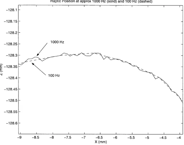
Figure 6-2: The filtering effect of different sampling rates
below the surface occurred in haptic space, but the virtual tool traced along the plane.
6.3
Low-Pass Filtering Effect
There is a low-pass filtering effect from the fact that the haptic loop runs at approx-imately 1000 Hz and the analysis loop runs at a much lower rate. Figure 6-2 shows identical trajectories sampled at 1000 Hz (solid) and 100 Hz (dashed). The region shown is the peak of the spherical artifact. Note that the amplitude of variation is on the order of 0.02 mm.
Haptic Position at approx 1000 Hz (solid) and 100 Hz (dashed)
I I I I I I I I I 1000 Hz 100 H z -128.15 -128.2 -128.25 -128.3 _-128.35 E N -128.45 -128.5 -128.55 -128.6 -9 -8.5 -8 -7.5
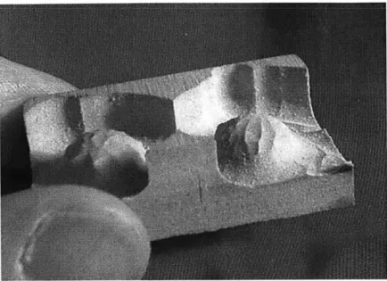
Figure 6-3: Spherical bumps cut in Ren-Shape plastic
6.4
Observations
We asked people of varying degrees of training, from those with negligible machining experience to skilled machinists, to try the system. They all took to the system fairly well. Figure 6-3 shows a sample part cut from Ren-Shape plastic. Below are some qualitative observations of their experiences with the system.
The more experienced machinists were willing to be more aggressive. The most timid users were those with little or no machining experience.
Users were split on the usefulness of the graphics. Most had a tendency to watch the machine directly, but one experienced machinist worked almost entirely from the graphical display. Several noted that if the graphical display were able to show where the tool had contacted the surface, they could better judge how well the spherical artifact had "cleaned up". One user found the display confusing when it was zoomed out, and much more helpful when it was scaled such that the apparent size of the sphere on the screen matched the size in the haptic space.
The skilled machinists were more adept at quickly removing material. They had a natural tendency to sweep the surface much like a CAM package zig-zagging across
a workspace. No doubt this comes from their extensive CAM experience.
At 3 inches per minute, the machine moved fairly slowly. In spite of this, one user (a skilled machinist) actually did most of his work below the speed limit (the speed limit indicator was not lit for much of his trial).
Most surprising was that no users seemed phased by the 3 inch per minute speed limit. They adapted naturally, and without prompting came to the conclusion that the system would be helpful for manual rapid moves on a larger machine.
Chapter 7
Conclusions
7.1
Observations and Lessons Learned
The Suzuki haptic device does not have sufficient force output. The device saturates at 5N output. It is not hard to push the device beyond this limit. This may partly be due to the sluggishness of free space, which is caused by the limited speed of the machine tool.
Of course, increasing the force output makes the device more dangerous to the
developer (bugs in the code) and user (instabilities). A more robust system would benefit from higher force output.
The Suzuki haptic has another limitation - awkward kinematics. The mechanical impedance across the workspace is far from uniform. This is understandable given that the device is intended for 5 degree of freedom work. For the 3-axis application, a PHANToM might have been a better choice. Then again, such a device would become useless if the move were made from controlling a 3-axis machine to a 5-axis machine.
7.2
Conclusions
A user can control a milling machine efficiently in 3 dimensional space. The technology exists at all levels of the system to drive a machine accurately and to provide the user
with intuition about the state of the system with haptic and graphical feedback. The virtual tool concept permits complex speed and collision analysis, because it provides an intermediate representation for the haptic to "servo" to.
The full-stick collision model is unsuitable for scanning or tracing surfaces. Some sort of slipping model (Adachi showed [1] that some friction is helpful) is necessary for these applications.
Chapter 8
Future Work
8.1
Introduction
This chapter suggests directions for future work related to the current project.
8.2
Simple Extensions
8.2.1
5-DOF
The current system can be extended into 5 degrees of freedom. Many problems that are relatively simple in 3-axis machining become considerably more complex in 5 degrees of freedom. In particular, collision detection and remediation become more challenging. However, the rewards increase as well. As the number of controllable axes increases, so does the benefit of full-DOF control.
8.2.2
Collision Detection
The collision remediation algorithm implemented here is very simple. Essentially, a simple shape was hard-coded into the decollide function. The design of the system lends itself to the easy integration of a more complex collision detection and remedi-ation function. Accurate, fast collision detection algorithms have been developed
[7],
and their implementation into a form compatible with the existing framework should be, in computer science parlance, a Simple Matter of Programming.
More complex collision remediation would most likely involve modeling not only the part, but also the tooling (currently, the tooling is kept safely below the tooling plane). Ho's algorithm treats the part as a point cloud, so a complex environment can be modeled as the superposition of the point clouds associated with each simple object. Ho's algorithm is not a drop-in solution, however, since it is penalty based and thus allows for penetration of the tool into the object. Some intermediate reme-diation steps would be required. Alternatively, the methods of Adachi [1], Zilles, and Salisbury [15] provide another possible path, with their intermediate representations and god-objects.
Professor Krzyztof Marciniak and I had a conversation in which he suggested a method for collision remediation. Essentially, the gradient of the surface is used to select the preferred direction to move, and the depth of penetration information helps determine how much the tool should back off for the next search.
8.2.3
3-D Stencil
With more sophisticated collision detection, our system can be used as a 3-D stencil. The motion of the machine is constrained in three dimensions to prevent gouging of the desired part. The user then exercises their judgment in deciding how fast to cut through the stock. For situations where the stock has unusual shape or properties, the
3-D stencil may be more efficient than generating a tool path, especially for roughing
and for prototype parts.
8.2.4
Servos instead of Steppers
Servomotors could replace the stepper motors in the system. Servomotors can gener-ally achieve much higher speeds and, because of position feedback, accuracies, than stepper motors. Stepper motors can "lose steps" if driven too aggressively, and thus require very conservative speed limits. Thus, at the simplest level, servomotors
in-crease speed and accuracy, and can be driven to the edge of their performance enve-lope.
Taken further, the position reported by the servomotors might replace or augment the virtual tool. Without the virtual tool, our work becomes just another telerobotic application with force feedback, but the accompanying technology still remains. A more complex control system might retain the virtual tool for rapid update, and periodically compare this to the real tool's reported position to update its speed limits and eliminate accumulated errors. Keeping the motor servo loop separate from the haptic servo loop accommodates time lag between the two, and maintains many of the beneficial features of the virtual tool system.
8.3
Looking Further
8.3.1
Feeling Tool Forces
Some of the machinists we spoke to expressed an interest in feeling the force expe-rienced by the tool. This would not only restore the sense of touch associated with manual machining, but would enhance it. In a conventional manual machine, the tool forces are filtered by the workpiece, tooling, machine bed, and lead-screw. Mea-surement of tool forces and reflection of them to the user would increase sensitivity substantially.
The technology for measuring tool forces exists. Sufficient feedback is likely to be available either by installing strain gauges on the machine, or by using a servo control system (the current machine is an open loop stepper controlled system), and having the servo-controller report the torques it is exerting to maintain the desired position. Two challenges stand in the way of this force feedback. First is the danger of instability. Manual machine tools maintain their passivity because of the non-back-drivability of lead-screws. The same low friction and inertia which permit free move-ment of the haptic are at odds with the damping required for stability. Virtual coupling methods [15] may prove useful.