Effect of bonding and aging temperatures on
bond strengths of Cu with 75Sn25In solders
The MIT Faculty has made this article openly available.
Please share
how this access benefits you. Your story matters.
Citation
Sasangka, W.A. et al. “Effect of bonding and aging temperatures on
bond strengths of Cu with 75Sn25In solders.” Electronics Packaging
Technology Conference, 2009. EPTC '09. 11th. 2009. 336-341. ©2010
IEEE.
As Published
http://dx.doi.org/10.1109/EPTC.2009.5416527
Publisher
Institute of Electrical and Electronics Engineers
Version
Final published version
Citable link
http://hdl.handle.net/1721.1/60303
Terms of Use
Article is made available in accordance with the publisher's
policy and may be subject to US copyright law. Please refer to the
publisher's site for terms of use.
978-1-4244-5100-5/09/$26.00 ©2009 IEEE 1 2009 11th Electronics Packaging Technology Conference
Effect of Bonding and Aging Temperatures on Bond Strengths of Cu with 75Sn25In Solders
W.A. Sasangka 1,2,3, C.L. Gan1,2, C.V. Thompson1,4, W.K.Choi3, J. Wei5
1. Advanced Materials for Micro- and Nano-Systems, Singapore-MIT Alliance, 4 Engineering Drive 3, Singapore 117576 2. School of Materials Science and Engineering, Nanyang Technological University, Singapore 639798
3. Institute of Microelectronics, A*STAR (Agency for Science, Technology and Research), 11 Science Park Road, Singapore Science Park II, Singapore 117685
4. Department of Materials Science and Engineering, Massachusetts Institute of Technology, Cambridge, Massachusetts 02139, USA
5. Singapore Institute of Manufacturing Technology, 71 Nanyang Drive, Singapore 638075
Abstract
In the present study, the interaction between thin film Cu and non-eutectic Sn-In is studied. The effects of the bonding and aging temperature on microstructure, IMC formation and also shear strength are investigated by SEM/EDX, XRD and shear testing. The bonding mechanism is proposed based on the obtained results. The bonding mechanism is proposed to occur over 2 stages:
• An increase in bonding temperatures leads to an increase in the true contact area, and
• The aging temperature leads to interdiffusion and assists formation of the IMC.
The type of IMC that forms is η phase (Cu6(Sn,In)5) which is
similar to the interaction between Cu and eutectic Sn-In. The shear strength increases with increasing the bonding temperature. On the other hand, the aging temperature does not have a significant impact on the shear strength. This indicates that the shear strength is mostly affected by the true contact area rather than the IMC formation.
Introduction
As the microelectronics industry deals with more and more complicated products, a new architecture paradigm is demanded. The paradigm is about having integration of different devices in the vertical direction, which is called 3D Integration [1]. There are many advantages gained by having this architecture such as shorter interconnects, allowing further scaling and giving more room for IC designers to explore more innovation. However, the realization of 3D Integration has many challenges. One of the most crucial challenges is how to develop a low temperature bonding process. This low temperature bonding is extremely important especially for those temperature sensitive devices such as MEMS, RF and Bio-related devices.
People have been pursuing a number of options in realizing bonding technology for 3D Integration [1]. However some of those options have limitations. Cu-Cu bonding is a very good option because it provides the best electrical conductivity. However it is difficult to bond Cu to Cu at low temperatures. It can only be bonded at 300oC or above. There
are some groups who can bond Cu to Cu at room temperature; however it has to be done either at ultra high vacuum [2] or at very high pressure [3]. Oxide to oxide bond is quite promising because it is able to bond at room temperature. However, it is very sensitive to humidity which makes the process unstable. Oxide to oxide bond also does not provide an electrical path, which is a disadvantage especially for microelectronics applications.
One promising technology for realizing low temperature bonding is by using solder materials as the glue agent between two metal surfaces. These solder materials are made of low melting point metals such as Sn, Pb, or In. Another characteristic of this bonding is its ability to form bonds at low temperatures by forming an Intermetallic Compound (IMC) with high melting point metal. This Intermetallic Compound has a unique property which its melting point is much higher than the solder material. Thus, it can sustain subsequent high temperature processes.
One of the potential material candidates for low-temperature bonding of Cu is Sn-In based solder. It has already been reported that it can bond at temperatures below 180oC. However, most of the reported work focused on
three-layer Cu/Solder/Cu bonding [4], bulk bonding [5], or eutectic composition 50Sn50In Bonding [6].
In this project, the interaction between thin film Cu and a non-eutectic composition of Sn-In is studied. The effects of the bonding and aging temperature on microstructure, IMC formation and also shear strength are investigated using Scanning Electron Microscope (SEM), Energy Dispersive Spectroscopy (EDX), X-Ray Diffraction (XRD) and shear tests. A bonding mechanism is proposed based on the results obtained.
Experimental Procedures
This study focused on the bilayer interaction between Cu/Ti/SiO2/Si dice and SnIn/Cr/SiO2/Si dice during bonding
and aging. The Cu and Sn-In chips size are 5 mm x 5 mm and 1 mm x 1 mm respectively. Cu/Ti and Sn-In/Cr films were deposited layer by layer, during sputter deposition. The as-deposited solder was characterized and it is shown that In and Sn layers interdiffused to form an alloy with non-eutectic composition of 75Sn25In. The thickness of the Cu film and solder layer is 1 um and 2.8 um respectively. The bonding was carried out at various bonding temperatures. Prior to bonding, both the solder and Cu surfaces were plasma cleaned using CF4+O2 for 30 seconds. The bonding was carried out using a
simple home-made bonder. The schematic of the process is shown in Figure 1.
After the bonding, some of the samples were aged at different temperatures for 5 hours. The details of the bonding and aging conditions are shown in Table 1.
Several characterization methods were employed to evaluate the effects of each parameter. The type of IMC was studied by using XRD. The bond strength was evaluated by using shear test. On the other hand, the cross section microstructure of the bonding interface was studied by
2 2009 11th Electronics Packaging Technology Conference
SEM/EDX. Prior SEM/EDX evaluation, the cross section of the samples were prepared by mounting the bonded samples in the epoxy, followed by grinding using sand papers and polishing using 1 um alumina powder.
Fig. 1. A schematic drawing of the layer structure for the bonding between 75Sn25In and Cu. Step 1: Depositing Solder and Cu Film, Step 2: Bonding.
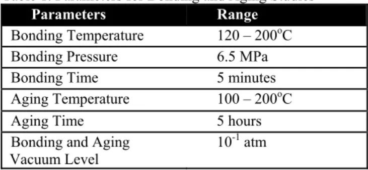
Table 1. Parameters for Bonding and Aging Studies
Parameters Range
Bonding Temperature 120 – 200oC
Bonding Pressure 6.5 MPa
Bonding Time 5 minutes
Aging Temperature 100 – 200oC
Aging Time 5 hours
Bonding and Aging
Vacuum Level 10
-1 atm
Results and Discussion
It is the nature of solder material to form a very rough surface when deposited on to a non-wettable surface, such as Cr, as clearly shown in Figure 2. The consequence of this characteristic is the true contact area between the solder and Cu during bonding will be much smaller than the nominal area.
(a) (b)
Fig. 2. SEM images of as-deposited 75Sn25In: a) Cross-sectional view and b) top view.
The reason behind having a solder film on top of Cr film is to eliminate the interaction between the solder and the film underneath. This interaction is usually observed in three layer/sandwich structure of Cu/Solder/Cu. From Figure 3, it
can be seen that Cr acts really well as a diffusion barrier. There is no interaction between Cr and Solder.
Fig. 3. TEM Cross Sectional view of sample bonded at 200oC for 5 mins and aged at 200oC for 5 hrs.
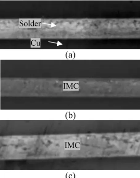
The microstructure and joint thicknesses were characterized using SEM/EDX. Cross-sectional SEM images of samples processed under different conditions are shown in Figures 4 – 6. It can be observed that the solder and Cu layers can still be clearly differentiated for samples bonded at 120oC.
On the other hand, the Cu and solder layers merged at higher bonding and aging temperatures, which is associated with IMC formation.
Based on phase diagram of Sn-In [7], the solidus and liquidus temperature of 75Sn25In are 135oC and 185oC,
respectively. By using this data, the solder states can be classified into three regimes which are solid state, partial liquid and liquid state. In order to have void free interface and transform the whole solder into IMC, the bonding and aging has to be done at 200oC which is at liquid state. Solid state
bonding gives a bonding interface with a lot of voids. This is originated by the rough surface of the solder. During the solid state bonding, not all the solder surface touches with Cu surface. The parts which are not touching, results voids in the interface. On the other hand, liquid state bonding helps the formation of voids free, as the molten solder can flow and fill the gaps in the interface.
The aging temperatures can also be classified into three regimes which are solid state, partial liquid and liquid state aging, based on Sn-In phase diagram [7]. The diffusivity of Cu in liquid state solder is much higher than the one in solid state solder. As already been reported, the phase transformation is preceded by the interdiffusion [8][9]. That is why, more IMC is found at higher aging temperatures (i.e partial liquid and liquid states).
(a) (b) Solder Cu Solder Cu 337
3 2009 11th Electronics Packaging Technology Conference
(c)
(d)
Fig. 4. Cross-sectional view of Cu/75Sn25In bonded at 120oC
and aged at different temperatures. Samples aged at a) 100oC, b) 150oC, and c) 200oC. Scale bar: 5um.
(a)
(b)
(c)
(d)
Fig. 5. Cross-sectional view of Cu/75Sn25In bonded at 150oC
and aged at different temperatures. Samples aged at a) 100oC,
b) 150oC, and c) 200oC. Scale bar: 5um.
(a)
(b)
(c)
(d)
Fig. 6. Cross-sectional view of Cu/75Sn25In bonded at 200oC
and aged at different temperatures. Samples aged at a) 100oC,
b) 150oC, and c) 200oC. Scale bar: 5um.
The joint thickness is measured from the cross sectional view of SEM. It is observed that the joint thickness decreases as the bonding temperature increases. As the solder becomes softer at higher temperatures, it became easier to deform when pressure was applied during bonding. The easier it is to deform, the less thick is the resulted joint thickness. Figure 7 shows the joint thickness as a function of bonding temperature, where joint thickness is defined as the summation of the Cu and solder layers.
The deformation of the solder is an indication of an enlargement of the true contact area. When the solder deforms, based on volume conservation model, the true contact area enlarges [10]. A rough solder consists of many asperities. During the bonding, the solder at the hills flows to the valleys of the asperities to fill up the voids. The smaller the joint thickness indicates the larger deformation of the solder. More deformation means that more solder materials flows from the hill towards the valleys of the asperities. As a consequence, the true contact area is larger. This is schematically shown in Figure 8.
Fig. 7. Average Bonding thickness vs. bonding temperature.
Fig. 8. Schematic Illustration of correlation between joint thickness and True Contact Area.
Solder Cu
Solder Cu Non Contact
Area (voids) Contact Area
Solder Cu Solder Cu IMC IMC IMC IMC IMC IMC Solder Cu 338
4 2009 11th Electronics Packaging Technology Conference
(a)
(b)
(c)
(d)
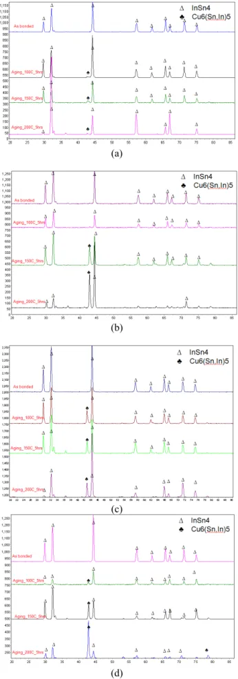
Fig. 9. XRD patterns for samples bonded and aged at different temperatures: a) bonded at room temperature , b) bonded at 120 oC, c) bonded at 150 oC and d) bonded at 200 oC
In order to identify the type of IMC that has formed, XRD characterization was employed. After shear tests, the solder side of the samples were sent for XRD analysis. The results are shown in Figure 9. For samples aged at low temperature, the solder surface is still dominated by the original solder peaks. As the aging temperature is increased, these peaks start to disappear, and new peaks which correspond to the η phase (i.e Cu6(Sn,In)5) start to appear. The observation of this phase
is similar to what has been reported in the interaction between Cu and 50Sn50In [5], whereby there is only one type of IMC (i.e η phase) that forms at temperatures below 200oC. An
interesting point to note is, even though the IMC peaks appear really strong at high temperature of aging, solder peaks are still remained. This is believed to be due to some areas which have remained in solder form while other areas are already converted into IMC. The area which are still remained in a solder forms are the area which are not in contact with Cu.
The XRD results show a very distinct observation with the similar studies that have been reported [6][4]. In this study, we observed that IMC is formed only after very long aging at high temperatures. Previous studies showed that IMC is able to form at even room temperature for relatively shorter time. This different could be due to the different layer structure. In this study, a bilayer structure is used. Thus, the interdiffusion of Cu and Sn-In happens only at the bonding interface. On the other hand, previous studies use a three layer structure. Underneath the solder film, there was a Cu film. Thus there is possibility the IMC formation on previous studies is originated by the interdiffusion of Sn-In with Cu film underneath.
Fig. 10. Schematic illustration of the proposed bonding mechanism.
Based on the results described in previous paragraphs, the following bonding mechanism is proposed:
• The as-deposited solder is very rough. Thus, when it is in contact with a Cu surface, the true contact area is not the same as the nominal area [11]. In fact, it can be one order magnitude smaller than the nominal area. However, as we increase the temperature and also apply the bonding pressure, the solder deforms and the true contact area enlarges. True contact area is defined as the areas which are in contact between solder and Cu surfaces. In Figure 10, it is represented as grey regimes, while the white regime is
5 2009 11th Electronics Packaging Technology Conference
associated with non-contact area. Intuitively, the higher the bonding pressure, the softer is the solder, which make it easier to deform, and thus the true contact area is larger. This mechanism is associated with creep mechanism for solid state and liquid flow for liquid state solder. Based on the observations, the bonding time of 5 mins is not sufficient for transforming the solder into IMC, thus the effect of bonding temperature is mainly for enlarging the true contact area.
• The role of aging on the other hand is to drive the interdiffusion which subsequently will precede the IMC formation. The IMC is represented as yellow regime in Figure 10. Intuitively, the higher the aging temperature, the more solder is transformed into IMC. This can be seen from XRD observation. It is also schematically shown in Figure 10. Because there is no pressure is applied during aging, the true contact area remained the same, before and after aging. There could be an effect of surface diffusion which might lead to enlargement of true contact area, but apparently the effect is not significant. Consequently, the area which is converted into IMC is the one which are in contact.
The shear strength as a function of the bonding and aging temperatures is shown in Figure 11. It is shown that the shear strength increases as the bonding temperature was increased. On the other hand, it was found that the aging temperature does not have a significant impact on the shear strength. This indicates that the shear strength is mostly affected by the increasing of true contact area rather than formation of IMC. Further investigation can be carried out in order to verify this in more quantitatively.
Fig. 11. Shear strength of the bonds vs. the bonding and aging temperatures.
Conclusions
• In order to transform the whole solder and Cu into an intermetallic (IMC), it is recommended that bonding be carried out above the melting point of the solder (in our case, 200oC) and the sample be aged for 5 hours at 200oC.
• The IMC that forms is the η phase (Cu6(Sn,In)5), which is
similar to the interaction between Cu and 50Sn50In. This gives new insight into why the compositions of Sn-In
solders do not affect the type of IMC that forms when they react with Cu at temperatures below 200oC.
• The bonding mechanism is proposed to occur over 2 stages:
o An increase in bonding temperature leads to an increase in the true contact area, and
o The aging temperature leads to interdiffusion and assists formation of the IMC.
• The shear strength increases with bonding temperature, while the aging temperature does not have a significant impact on it. This indicates that the shear strength is mostly affected by the true contact area rather than the IMC formation.
Acknowledgement
The authors would like to thank Mr Riko I-Made for useful discussions and Institute of Materials Research and Engineering for XRD Characterization. Wardhana Sasangka would like to thank Singapore-MIT Alliance for providing scholarship.
References
[1] K. Saraswat, K. Banerjee, A. Joshi, P. Kalavade, P. Kapur, and S. Souri, “3-D ICs: Motivation, performance analysis, and technology,” Solid-State Circuits Conference, 2000. ESSCIRC '00. Proceedings of the 26th European, 2000, pp. 406-414.
[2] R. Tadepalli and C.V. Thompson, “Formation of Cu--Cu interfaces with ideal adhesive strengths via room temperature pressure bonding in ultrahigh vacuum,” Applied Physics Letters, vol. 90, Apr. 2007, pp. 151919-3.
[3] X.F. Ang, J. Wei, Z. Chen, and C.C. Wong, “Ambient Copper-Copper Thermocompression Bonding using Self-Assembled Monolayers.”
[4] L. Yan, C. Lee, D. Yu, A. Yu, W. Choi, J. Lau, and S. Yoon, “A Hermetic Seal Using Composite Thin-Film In/Sn Solder as an Intermediate Layer and Its Interdiffusion Reaction with Cu,” Journal of Electronic Materials, vol. 38, Jan. 2009, pp. 200-207.
[5] S. Sommadossi and A.F. Guillermet, “Interface reaction systematics in the Cu/In-48Sn/Cu system bonded by diffusion soldering,” Intermetallics, vol. 15, Jul. 2007, pp. 912-917.
[6] Won Kyoung Choi, Daquan Yu, Chengkuo Lee, Liling Yan, A. Yu, Seung Wook Yoon, J. Lau, Moon Gi Cho, Yoon Hwan Jo, and Hyuck Mo Lee, “Development of low temperature bonding using in-based solders,” Electronic Components and Technology Conference, 2008. ECTC 2008. 58th, 2008, pp. 1294-1299.
[7] B.J. Lee, C.S. Oh, and J.H. Shim, “Thermodynamic assessments of the Sn-In and Sn-Bi binary systems,” Journal of Electronic Materials, vol. 25, 1996, pp. 983-991.
[8] B.J. Lee, N.M. Hwang, and H.M. Lee, “Prediction of interface reaction products between Cu and various solder alloys by thermodynamic calculation,” Acta Materialia, vol. 45, 1997, pp. 1867-1874.
6 2009 11th Electronics Packaging Technology Conference
[9] C.V. Thompson, “On the role of diffusion in phase selection during reactions at interfaces,” Journal of Materials Research, vol. 7, 1992, pp. 367-373.
[10] J. Pullen and J.B.P. Williamson, “On the Plastic Contact of Rough Surfaces,” Proceedings of the Royal Society of London. Series A, Mathematical and Physical Sciences, vol. 327, Mar. 1972, pp. 159-173.
[11] H.L. Leong, C.L. Gan, C.V. Thompson, K.L. Pey, and H.Y. Li, “Application of contact theory to metal-metal bonding of silicon wafers,” Journal of Applied Physics, vol. 102, Nov. 2007, pp. 103510-9.