Publisher’s version / Version de l'éditeur:
Interface (Journal of the Roof Consultants Institute), 21, April 4, pp. 17-21, 2003-04-01
READ THESE TERMS AND CONDITIONS CAREFULLY BEFORE USING THIS WEBSITE. https://nrc-publications.canada.ca/eng/copyright
Vous avez des questions? Nous pouvons vous aider. Pour communiquer directement avec un auteur, consultez la première page de la revue dans laquelle son article a été publié afin de trouver ses coordonnées. Si vous n’arrivez pas à les repérer, communiquez avec nous à PublicationsArchive-ArchivesPublications@nrc-cnrc.gc.ca.
Questions? Contact the NRC Publications Archive team at
PublicationsArchive-ArchivesPublications@nrc-cnrc.gc.ca. If you wish to email the authors directly, please see the first page of the publication for their contact information.
NRC Publications Archive
Archives des publications du CNRC
This publication could be one of several versions: author’s original, accepted manuscript or the publisher’s version. / La version de cette publication peut être l’une des suivantes : la version prépublication de l’auteur, la version acceptée du manuscrit ou la version de l’éditeur.
Access and use of this website and the material on it are subject to the Terms and Conditions set forth at
Wind pressure measurement on fullscale flat roofs
Baskaran, B. A.; Savage, M. G.
https://publications-cnrc.canada.ca/fra/droits
L’accès à ce site Web et l’utilisation de son contenu sont assujettis aux conditions présentées dans le site LISEZ CES CONDITIONS ATTENTIVEMENT AVANT D’UTILISER CE SITE WEB.
NRC Publications Record / Notice d'Archives des publications de CNRC:
https://nrc-publications.canada.ca/eng/view/object/?id=938d37f5-808d-4659-acc7-ffb7719d91d3 https://publications-cnrc.canada.ca/fra/voir/objet/?id=938d37f5-808d-4659-acc7-ffb7719d91d3
Wind pressure measurements on full scale flat roofs
Baskaran, A.; Savage, M.G.
NRCC-46291
A version of this document is published in / Une version de ce document se trouve dans : Interface, Journal of the Roof Consultants Institute, v. 21, no. 4, April 2003, pp. 17-21
Wind pressure measurements on full scale flat roofs
1A.Baskaran and M.G.Savage
Research Officers
National Research Council Canada 1500 Montreal Road
Ottawa, Canada K1A 0R6 Bas.baskaran@nrc.ca
ABSTRACT
A flat roof surface is known to be subjected to unusually high suction associated with a pair of vortices created under diagonally skewed wind. Prediction of the wind load and its influence on the roof system is an important engineering topic but wind tunnel testing of this situation is not easy with a scaled model. Considering the physics of wind flow for the most critical case, a possibility to use a full-roof configuration has been investigated. Results are found to be encouraging, which allows the use of much accurate structural details of roofing system, such as flexible membranes.
1 INTRODUCTION
A flat roof surface is known to be subjected to unusually high suction induced by a pair of “horse shoe” vortices caused by the wind coming diagonally facing a corner of the building (Kind and Wardlaw, 1979). This phenomenon can cause very serious damage to the roofing system such as dislocation of concrete “pavers” or insulation boards. It is also known that some architectural features of the building such as parapets varying by their height have some influence on these phenomena (Baskaran, 1986). At the same time, wind tunnel testing of this situation is a challenging task because the extent of damage depends a lot on the structural details, which can hardly be modelled properly in a reduced scale.
Since the early 1970’s, several wind tunnel studies have focussed on this issue and there are commonly observed difficulties in modelling the structural details (Kind, Savage & Wardlaw 1988). Wind tunnel testing of a full scale building, on the other hand, would be nearly impossible. By taking advantage of a very large test section of the 9m × 9m wind tunnel at the National Research Council Canada (NRCC), Kind and Wardlaw carried out a series of comprehensive studies of the wind effects on a variety of roof assemblies during the period of 1975 – 1990, which formed the basis for several roofing standards internationally. In wind tunnel studies models had a rigid roof and its deformation due to wind suction was assumed negligible. However, in a mechanically attached single ply roof, the membrane may be inflated once high suction is applied, which in turn may give a different wind induced pressure distribution. Another engineering concern is the structural detail of how the roofing system is installed on the building. In order to examine these points, a pilot study was carried out.This paper reports benefits to use full-scale roof component materials for the wind tunnel tests of such roof sections.
Part of this paper was published at the 10th
2 EXPERIMENTS
The models used for this series of tests are 1/10 in linear scale and equipped with full scale roof component materials, as shown in the Fig.1. All tests were conducted at the 9m × 9m wind tunnel. Two different types of roofing membranes were used for this experiment: one is a reinforced poly-vinyl-chloride (PVC) membrane and the other is a non-reinforced membrane made of ethylene-propylene-diene-monomer (EPDM). Physical, mechanical and chemical properties of these two membranes are significantly different (Baskaran, Paroli & Booth 1997). This is because PVC is a thermoplastic polymer whereas EPDM is a rubber based thermoset material.
Fig.1: Roof assembly module with full scale components
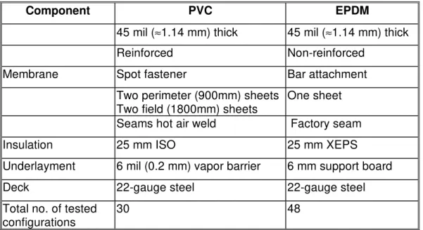
A typical mechanical property of these membranes is shown in Fig. 2, which compares the stress-strain behaviour of two materials under the same tensile stress rate. The PVC membrane has significantly higher breaking load compared to EPDM. However, due to its reinforced nature, it can stretch only about 1/8 of that of EPDM. Differences of two roofing assemblies used for the wind tunnel study are summarized in Table 1. The membranes were equipped with 89 and 100 special pressure taps for PVC and EPDM models, respectively, in a way that their influence on mechanical properties of membrane would be minimum. For both roof configurations, the influence of wind speed and direction and building height on wind pressure were examined. Details of the wind simulation are found elsewhere (Savage et al. 1997; Baskaran et al. 1996).
Fig.2. Mechanical property of typical membranes Table 1: Differences between PVC and EPDM roof assemblies
3 RESULTS AND DISCUSSION
Figs. 3 and 4 compare the PVC and EPDM system response. They present an overall pattern of the mean pressure distribution for wind approaching normal to the building side and for the 45° skewed wind for each of the PVC and EPDM cases. High suction near the up-wind corner and moderate pressure distribution for the rest of the roof are commonly observed for both systems. The characteristic “horse-shoe” vortex zone for the 45° wind case is again clearly identified. These features are similar to the previous wind tunnel studies on rigid models.
Wind induced suction over the assembly results in membrane deflection between the attachments to the roof deck. As indicated in Table 1, the PVC roof is composed of four sheets that are attached to the structural deck using mechanical fasteners. These four areas are referred to as S1, S2, S3 and S4 in Fig.3. During wind tunnel investigations, four zones of membrane ballooning were noticed. For the PVC roofs, maximum deflection was observed at the sheet S3, which is wider than S1and S2 and it is not restrained along its edges as S4. For the roofs with non-reinforced EPDM membrane, measured deflections were much higher than the PVC roofs. It is critical to note that the observed pressure distribution pattern was totally different from the deflected shape of the membrane. This indicates that neither the number of sheets used nor the way the membranes are attached to the roof deck had any significant influence on the wind-induced mean pressure distribution patterns. This also indicates that the deflected shape stays inside of the low pressure separation bubble and it does not influence the mean pressure distribution.
EPDM roofs generally experienced higher mean suction than the PVC roofs for the same wind conditions. Maximum measured mean suction coefficient for EPDM was –4.5 compared to that of −2.4 for the system with PVC membranes. Also, the spatial distribution is different between the two cases. For the normal wind, as shown in Fig.3, the measured pressure is about –0.5 when x/L = 0.4 in the case of the PVC roofs. For the same location, the EPDM roof experienced –0.9 (Fig.4). Positive pressure on the roof assembly indicates reattachment of the separated flow over the roof surface. Figs.3 and 4 indicate longer distance before the reattachment for the case of PVC roofs compared to EPDM roofs.
Fig.4: Mean pressure distribution with EPDM roof membranes
In order to help understand the difference of wind effects between the two roofs, spectral analyses were performed on the pressure time histories. Fig.5 shows the normalized spectral density of typical pressure records with PVC and EPDM roofs, measured at the perimeter region. A low pass filter with cut-off frequency of 50 Hz was used to eliminate high-frequency noise existed with the pressure records. The spectral density function of the approaching wind is also included for comparison. Three distinct response regions have been noticed at three different frequency bands as follows: 1) Up to a frequency of about 2 Hz, the approaching wind and PVC record show similar energy distribution. In comparison to this, the EPDM record has less energy in the same frequency range. 2) For the frequency of 2 to 10 Hz, both PVC and EPDM have similar energy distribution, which is also higher than the energy of the approaching wind. 3) For frequencies above 10 Hz, the energy content of EPDM is much higher than that of the approaching wind or the PVC. This is due to the fact that a flexible membrane of EPDM tends to experience a greater fluttering effect compared to less flexible membrane of PVC. The fluttering vibration is caused by the approaching wind.
To identify the effects of membrane motion on the induced surface pressures, the above analysis could be extended to come up with the concept of a transfer function. This provides the ratio of membrane response pressure to the applied flow pressure fluctuations, as measured on rigid roof pressure models, at each particular frequency. The transfer function developed as such could be used for the correction of pressure readings measured on rigid roof models to include the membrane vibration effects. The success of this approach could open up a much larger and more general database for analyses useful for the design of roofing systems.
Fig.5: Comparison of pressure spectra from the PVC and EPDM roof assemblies 4 CONCLUSIONS
Wind tunnel studies were also carried out with the models on full-scale roof component materials. Flexible roof membranes could change the geometrical shape of the roof under suction and the resulteant shape varies depending on the direction of approaching wind and the materials and layout of the membrane attachments to the deck. However, the overall mean pressure distribution pattern on flat roofs was found to not be significantly influenced by the materials. This provides the possibility of introducing a transfer function to take the dynamic effects of membrane vibration into account as a correction factor applicable to the measured results from rigid flat roof models.
REFERENCES
Baskaran, A. 1986. Wind loads on flat roofs with parapets, M.Eng. thesis, Concordia University, Canada.
Baskaran, A., R.M. Paroli & R.J. Booth 1997. Wind performance evaluation procedures for roofing systems: Current status and future trends, Proceedings of the 5th International Conference on Building Envelope Systems & Technology, Bath, U.K: 37-54.
Baskaran, A., M.G. Savage, F. Alfawakhiri & K.R. Cooper 1996. Pressure distribution data measured during the October 1995 wind tunnel tests on a mechanically attached EPDM single ply roofing systems, LTR-A-004, National Research Council Canada.
Kind, R.J., M.G. Savage & R.L. Wardlaw 1988. Prediction of wind-induced failure of loose laid roof cladding systems, Journal of Wind Engineering & Industrial Aerodynamics 29: 29-37. Kind, R.J. & R.L. Wardlaw 1979. Model studies of the wind resistance of two loose laid roof
insulation systems, LTR-LA-234, National Research Council Canada.
Melbourne, W.H. 1982. Wind tunnel blockage effects and corrections, Wind Tunnel Modeling
for Civil Engineering Applications, Cambridge University Press: 197-216.
Savage, M.G, K.R. Cooper & A. Baskaran 1997. Wind tunnel investigation of the wind loads on a single ply mechanically attached PVC roofing system, LTR-A-012, National Research Council Canada.
ACKNOWLEDGEMENTS
Authors acknowledge the technical insight provided by Dr. D. Surry on Fig.5. The discussion and encouragement towards the project by Mr. R.L. Wardlaw are greatly appreciated.The presented research is being carried out for a consortium - Special Interest Group for Dynamic Evaluation of Roofing Systems (SIGDERS). SIGDERS was formed from a group of partners who were interested in roofing design. These partners included: Manufacturers - Atlas Roofing Corporation, Canadian General Tower Ltd., GAF Materials Corporation, GenFlex Roofing Systems, Firestone Building Products Co., IKO Industries Ltd., Johns Manville, Sarnafil, Soprema Canada and Stevens Roofing Systems. Building Owners - Canada Post Corporation, Department of National Defence, Public Works and Government Services Canada. Industry
Associations - Canadian Roofing Contractors' Association, Canadian Sheet Steel Building
Institute, Industrial Risk Insurers, National Roofing Contractors’ Association and Roof Consultants Institute. Research Agencies-Institute for Research in Construction, Institute for Aerospace Research and Canadian Construction Material Centre.
Fig.2. Mechanical property of typical membranes 0 2 4 6 8 10 Strain 0 10 20 30
Str
es
s (M
Pa
)
PVC EPDMFig.3: Mean pressure distribution with PVC roof membranes -S2 S3 S4 S1 Fastener Attachment -1.2 to 0.1 -2.4 to 0.0
Fig.4: Mean pressure distribution with EPDM roof membranes
Fastener Attachment
-1.6 to 0.0
Fig.5: Comparison of pressure spectra from the PVC and EPDM roof assemblies 0 1 10 100 Frequency , f (Hz) 0.0 0.1 0.2 0.3 0.4 0.5 0.6 σ N o rm a lize d Sp e c tr a l De n s it y , f s (f )/ ^ 2 PVC EPDM Wind
Table 1: Differences between PVC and EPDM roof assemblies
Component PVC EPDM
45 mil (≈1.14 mm) thick 45 mil (≈1.14 mm) thick
Reinforced Non-reinforced
Membrane Spot fastener Bar attachment Two perimeter (900mm) sheets
Two field (1800mm) sheets
One sheet Seams hot air weld Factory seam
Insulation 25 mm ISO 25 mm XEPS
Underlayment 6 mil (0.2 mm) vapor barrier 6 mm support board Deck 22-gauge steel 22-gauge steel Total no. of tested
configurations