READ THESE TERMS AND CONDITIONS CAREFULLY BEFORE USING THIS WEBSITE.
https://nrc-publications.canada.ca/eng/copyright
Vous avez des questions? Nous pouvons vous aider. Pour communiquer directement avec un auteur, consultez la première page de la revue dans laquelle son article a été publié afin de trouver ses coordonnées. Si vous n’arrivez pas à les repérer, communiquez avec nous à [email protected].
Questions? Contact the NRC Publications Archive team at
[email protected]. If you wish to email the authors directly, please see the first page of the publication for their contact information.
Archives des publications du CNRC
This publication could be one of several versions: author’s original, accepted manuscript or the publisher’s version. / La version de cette publication peut être l’une des suivantes : la version prépublication de l’auteur, la version acceptée du manuscrit ou la version de l’éditeur.
Access and use of this website and the material on it are subject to the Terms and Conditions set forth at
Guideline for Seismic Upgrading of Building Structures
https://publications-cnrc.canada.ca/fra/droits
L’accès à ce site Web et l’utilisation de son contenu sont assujettis aux conditions présentées dans le site LISEZ CES CONDITIONS ATTENTIVEMENT AVANT D’UTILISER CE SITE WEB.
NRC Publications Record / Notice d'Archives des publications de CNRC:
https://nrc-publications.canada.ca/eng/view/object/?id=d27329ea-84aa-4866-a29e-77c38ffda596 https://publications-cnrc.canada.ca/fra/voir/objet/?id=d27329ea-84aa-4866-a29e-77c38ffda596
1+1
Council CanadaNational ResearchConseil national de recherches Canada
5\. '.
A
.J...IftC·ClftC
Guideline for
Seismic
Upgrading of Building
Structures
Guideline for Seismic
Upgrading of Building
Structures
Prepared by:
Institute for Research in Construction National Research Council of Canada Funded by:
Public Works and Government Services Canada British Columbia Buildings Corporation Canada Mortgage and Housing Corporation Institute for Research in Construction © National Research Council of Canada December 1995
ISBN 0-660-16262-8 NRCC 38857
NOTICE
This Guideline has been prepared by the Institute for Research in Construction (IRC) for the organizations listed above. With the agreement of these organizations the Guideline is being made available to interested individuals or organizations for their information and review. This Guideline is not to be interpreted as replacing or superseding applicable building regulations. Neither IRC nor the sponsoring organizations assume any liability for the use of this document.
GUIDELINE FOR SEISMIC UPGRADING OF BUILDING STRUCTURES
Preface
Summary
This Guideline provides information and advice on the seismic upgrading of existing building structures, and is intended for use by qualified structural engineers. Itis a companion document to the recently
published Guidelines for Seismic Evaluation of
Existing Buildingsl and the Manualfor
Screening of Buildings for Seismic
Investigation,2 both of which are related to the
National Building Code of Canada.3
The Guideline describes conventional techniques of seismic upgrading of building structures and discusses their relative merits based on the objectives of seismic upgrading and the principal considerations in their choice and design. Italso describes innovative seismic upgrading techniques such as supplementary damping and contains references to more detailed information on such techniques. Itdoes not include techniques for upgrading of non-structural building components.
Background
This Guideline is based in part on
NEHRP Handbook of Techniques for Seismic Rehabilitation of Existing Buildings,4but the
material has been reorganized and shortened considerably. Also, this document contains more guidance on innovative techniques than does the NEHRP Handbook.
The first draft of this Guideline was produced with the support of Public Works and Government Services Canada. Based on comments received, the draft has been improved for publication with the support of B.C. Buildings Corporation and Canada Mortgage and Housing Corporation.
The Guideline was prepared by the following persons:
D.E. Allen, IRCfNRC, Ottawa, Ontario
Principal Investigator Main Contributors:
L.Bell CWMM, Vancouver, B.C.
S. Cherry University of British Columbia,
Vancouver, RC.
F.Knoll Nicolet Chartrand Knoll Ltee.,
Montreal, Quebec
R. Lo Klohn Crippen Consultants Ltd.,
Richmond, B.C.
l.R. Rainer IRCfNRC, Ottawa, Ontario
The review of the draft document by B.C. Hydro, Hydroelectric Engineering Division, is gratefully acknowledged, as are the comments received from a number of other individuals and companies.
Table of Contents
1. INTRODUCTION 1
1.1 Purpose of the Guideline l
1.2 Scope and Limitations 1
1.3 How to Use the Guideline 1
2. SEISMIC DEFICIENCIES OF THE BUILDING STRUCTURE 3
2.1 Lack of Integrity/Redundancy 3 2.2 Inadequate StrengthlDuctility 3 2.3 Inadequate Stiffness/Adjacent Buildings 3 2.4 Irregularities/Load Transfer .4 3. PRINCIPLES OF SEISMIC UPGRADING 5 3.1 Objectives of Upgrading 5 3.2 Conventional Upgrading Techniques 5
3.3 Special Upgrading Techniques 7
3.4 Considerations in the Choice of
Upgrading Techniques 7
3.4.1 Structural Considerations 7
3.4.2 Other Considerations 10
3.5 Design Criteria, Testing of Special
Devices ll
4. UPGRADING TECHNIQUES·
CONVENTIONAL 13
4.1 New Shear Walls, Bracing or Moment
Frames 13
4.2 Upgrading Existing Moment
Frames 15
4.3 Upgrading Existing Braced
Frames 17
4.4 Upgrading Existing Shear Walls 18
4.5 Upgrading Existing Diaphragms 23
4.6 Techniques for Lateral Support of
Walls and Parapets 27
5. UPGRADING TECHNIQUES·
SPECIAL 29
5.1 Supplementary Damping 29
5.2 Base Isolation 31
5.3 FRP Overlays and Encasements 33
6. UPGRADING TECHNIQUES·
FOUNDATIONS 35
6.1 Conventional Techniques for
Upgrading Foundations 36
6.2 Soil Stabilization 38
REFERENCES 43
APPENDIX A: CHECKLIST OF
Chapter 1
Introduction
1.1
Purpose of the
Guideline
1.3
How to Use the
Guideline
Many buildings in seismic areasacross Canada were built before there was an adequate understanding of earthquake resistance. Many of these buildings would be deemed unsafe by cunent building codes. Also, because code requirements are written for the design of new buildings and not for the evaluation of existing buildings, the cost of upgrading an existing building to the cunent code can be very large, as well as destructive to its heritage value. A set of alternate procedures for evaluating existing buildings was therefore prepared by NRC and published in the Guidelines for Seismic Evaluation of
Existing Buildingsl (hereafter refened to as
"Guidelines for Seismic Evaluation").
This new Guideline was prepared to help engineers design the seismic upgrading using appropriate techniques for conecting the seismic deficiencies identified using the above NRC evaluation guidelines. The techniques described herein include conventional methods that were employed in the past, as well as recently developed special procedures, such as supplementary damping and base isolation. The document discusses the relative merits of the vatious techniques, based on earthquake engineering principles, observed seismic perfonnance, construction procedures, and costs.
1.2
Scope and Limitations
This document provides descriptions and discusses the relative merits of various techniques for seismic upgrading of buildings found by evaluation to be seismically deficient.
Itis not intended for the repair of seismically damaged buildings, although some of the techniques may be useful for such repairs. The techniques are described generically,
accompanied by sketches to illustrate concepts. This document does not provide specific design criteria or specific details suitable for direct application, nor does it recommend specific devices.
The Guideline should first be read from the beginning. Afterwards it may be
convenient to begin with AppendixA,which
contains checklist tables of upgrading
techniques, one table for each major structural system. These techniques are described in more detail in Chapters 4 to 6, identified by the appropriate page and figure numbers in the Appendix A checklist tables. The relative merits of each technique are based on objectives and principles involved in seismic upgrading described in Chapter 3. Chapter 2 reviews the types of seismic deficiencies found in existing buildings.
The design of upgrading of existing buildings involves a greater number of uncertainties and constraints than the design of new buildings. Consequently, more judgment is needed for design of the upgrading, including the choice of techniques, than in the design of new buildings. In addition, seismic upgrading is a relatively new activity and innovative techniques are in various stages of development. This document, therefore, places
more emphasis on principles, experience, and access to information than on specific requirements and criteria.
Chapter 2
Seismic Deficiencies of the
Building Structure
The choice of techniques for seismic upgrading of a building structure depends on its seismic deficiencies. Appendix C of the
Guidelines for Seismic Evaluationl provides a master list of 123 potential deficiencies. For this document it is useful to combine these deficiencies into the following more general categories:
• Lack of integrity/redundancy • Inadequate strength/ductility
• Inadequate stiffness/adjacent buildings • ItTegularities/load transfer.
These categories are broken down into more specific deficiencies in Tables Al to
A6 in AppendixA. As a background to the
principles of seismic upgradingHcィ。ーエ・イNSセL
the categories are discussed in more detaIl In this chapter.
2.1
Lack of Integrity!
Redundancy
If the structure is not integrally connected, it will start to come apart dming a strong earthquake. Expelience shows that t.he most serious deficiency leading to progreSSIve collapse of a building is lack of adequate anchorage of masonry or precast elements (walls, columns, beams, slabs) to the
diaphragms and to each other. Other. .
deficiencies in integrity relate to contInmty of diaphragms (such as wood or precast concrete), especially around openings, and tying together of shear walls (tie-downs and connections between infill and frames).
Redundancy is another property of a building structure which, as shown by earthquake experience, helps prevent failures. Redundancy concerns not only the redundancy of the structure in resisting lateral loads (multiple shear walls and frames) but also .its ability to resist vertical loads after local faIlure of a component such as a shear wall.
Redundancy, however, is not always an advantage, especially when the "redundant" elements are of a blittle character, as discussed later.
2.2
Inadequate Strength!
Ductility
The safety of a building, as well as the control of damage to the structure, depends very much on the behaviour of the building structure when subjected to large earthquake forces. The safety depends not only on the strength of the building structure but on its behaviour under cyclic overloading -its ductility, -its energy-absorption capacity and its stiffness. In the case of moment frames, the safety of the building also depends on the ability of the frames to support the vertical loads in displaced configuration (the P-6 effect). Most evaluation statements in the Guidelines for
Seismic Evaluation! concern such properties.
Ductility under cyclic loading is therefore an important consideration, but it is often difficult to achieve through upgrading of existing structures. Itcan be achieved, however, by altering the structure by vaIious techniques, as described in Chapter 3.
2.3
Inadequate Stiffness!
Adjacent Buildings
Earthquake experience has shown that the lateral stiffness of the vertical structure is a major factor in the prevention of life-threatening failures and in the control of building damage. Lateral stiffnessエィ・イセヲッイ・becomes an important factor to be conSidered in the choice of upgrading for buildings in medium to high seismic zones. It is less important in low seismic zones「・」。オウセ
seismic ground displacements are relatIvely small.
Adequate in-plane stiffness of horizontal diaphragms (wood, metal deck) is also an important consideration in preventing instability failure of masonry walls in high seismic zones. This is covered in Appendix A of the Guidelines for Seismic Evaluation.!
GUIDELINE FOR SEISMIC UPGRADING OF BUILDING STRUCTURES
Compatibility in lateral stiffness of the vertical elements of the building, including architectural components, is another impOliant consideration. The stiff elements attract the load and therefore fail first, whereas the flexible elements do not carry much load until after the stiff elements have failed. If,as a consequence of this, part of the building loses its vertical support, a dangerous progressive collapse can occur.
Related to lateral stiffness of the vertical structure is pounding from adjacent buildings or from adjacent parts of the same building separated by movement joints. Tall moment-frame buildings are flexible and can impact adjacent low stiff buildings. Damage can be very severe, particularly if storey levels do not line up. Impacts can also occur within a building if heavy components are not laterally supported by the structure.
2.4
Irregularities/Load
Transfer
Dissymmetry in the layout of the lateral load-resisting structure or in the mass distribution can cause major torsional
movements in an earthquake. Sudden changes in stiffness or discontinuities in both vertical and horizontal elements attract large local forces or deformations, leading to local rupture. Types of ilTegularities that attract large localized forces include:
• open fronts (shops, garages, etc.) in exterior walls at ground floor level • columns supporting shear walls
• short concrete columns in moment frames (e.g., due to partial infills)
• shear walls or bracing offset from floor to floor.
Open fronts of buildings are a soft storey condition which has resulted in many collapses in recent earthquakes. Columns SuppOliing shear walls are subjected to very large overturning forces, and short concrete columns attract large lateral forces and fail in a brittle shear mode. Offset shear walls or bracing result in large localized diaphragm forces.
Chapter 3
Principles of Seismic Upgrading
Objectives of Upgrading
3.2
3.1
Once rehabilitation of a building is deemed necessary for safety or other reasons (e.g., post-disaster function), there are a number of objectives, including life safety, that must be considered in the choice and design of the seismic upgrading. These may be listed as follows:
(I) life safety
(2) prevention of damage to building
components and contents (damage control) (3) minimum disruption of building use during
upgrading
(4) proper functioning of the building after upgrading
(5) acceptable building appearance and heritage value
(6) minimum cost.
Objectives (3) to (6) are usually interrelated in the sense that they seek
minimum structural intervention, provided the
objectives of life safety and damage control are met. Minimum intervention will vary
substantially from building to building and its achievement is very much a practice-oriented exercise involving considerable interaction of the engineer with the architect, owner and contractors. This chapter first summarizes available upgrading techniques and then discusses the principles the engineer will have to consider in the choice and design of the upgrading.
Conventional
Upgrading Techniques
Conventional upgrading techniques do not require special devices or newmaterials. The following basic techniques are cUlTently used for seismic upgrading:
New Shear Walls. This includes
reinforced concrete, reinforced masonry, plywood-sheathed wood-stud walls and steel-plate shear walls. New shear walls should preferably be located between existing columns and connected to them, not only because this arrangement is structurally more effective but also because it may avoid the necessity of new foundations. New shear walls can be used to reduce torsional or other forces due to irregularities, as well as to increase strength and stiffness of the existing structure.
New Bracing. This can be executed
in steel, wood, or occasionally in reinforced concrete. New bracing is usually in the vertical plane but can also be in the horizontal plane. The bracing should preferably be located within existing frames for the same reasons that shear walls should be located between columns. As is the case for shear walls, new bracing can be used to reduce torsional or other forces due to irregularities of the structure, as well as to increase the
strength and stiffness of the vertical structure or diaphragms. A new technique is to incorporate special damping devices in new bracing; this is discussed in 5.1.
Infills. The systems described above
for new shear walls can also be used to fill openings that are no longer needed in existing walls or diaphragms. Infills enhance stiffness as well as strength of existing walls or diaphragms. However, adequate strength of surrounding frame members must be assured.
GUIDELINE FOR SEISMIC UPGRADING OF BUILDING STRUCTURES
Overlays. This includes cast-in-place
concrete (shotcrete, toppings, etc.) and plywood. Mesh-reinforced cements or plaster and fibre-reinforced plastics (see 5.3) may also be used for safeguarding brittle components such as hollow clay tile or concrete columns. Overlays increase strength and stiffness of shear walls and diaphragms, and can be used as a means of tying different elements together for better integrity of the structure.
Strengthening Members. This
includes adding components to strengthen or stiffen existing members, or to make them more ductile. A variety of methods exist, including reinforcing existing masonry (hollow block or coring of brick masonry), encasing with reinforced concrete, steel plates or fibre-reinforced plastics, and lateral bracing to reduce buckling length. Sometimes it is more economical and faster to replace existing members with new ones, as in the case of bracing systems. Sometimes it is better to strengthen existing components, such as unreinforced load-bearing masonry. Besides increasing strength, member strengthening can be used to make the structure more ductile by altering the mechanism of failure, for example by making reinforced-concrete columns stronger than the beams.
Strengthening Joints. This includes
converting shear connections into moment connections in steel frames, strengthening bracing connections so that yielding takes place in the bracing members rather than brittle failure in the joints, nailing of wood sheathing, or welding of metal deck for strengthening diaphragms. Strengthening joints can be used to increase the strength of the structure and to make the structure more ductile by altering the mechanism of failure.
Anchorage/Ties. This includes
anchorage of walls to floor or roof diaphragms for lateral support of the walls and for transfer of shear from the diaphragms to the vertical structure. Italso includes anchorage of the vertical structure into the foundations. Anchorage devices provide integrity to the structure and are generally the most effective technique in terms of cost-versus-life-safety benefit.
Anchorage devices will also be useful when tying adjacent buildings or building portions together, in order to make them act as a unit and to avoid collision and hammering. Vertical tie-downs through floors, splices between diaphragm elements (e.g., at opening corners or between beams at supports) also provide integrity to the structure.
Precast assembly-type structures have not performed well in recent earthquakes as a result of connection failures and relative movements at the joints between the precast elements. One remedy is to strengthen and stiffen the ties.
Chords/Collectors. A chord is a
continuous member placed along the outside edge of the diaphragm. Itacts as a flange to resist diaphragm moment. A collector is a member incorporated in the diaphragm which 'collects' diaphragm shear and transfers it to the vertical structure. Chords and collectors tie diaphragms together and transfer diaphragm forces into the vertical structure. Sometimes reinforced-concrete toppings, plywood sheathing or steel trusses can accomplish the same objective. Collectors are sometimes called 'drag-struts.'
Foundations. Upgrading of
foundations is generally expensive and should be avoided if possible except where, as shown by earthquake experience, foundation failure results in severe consequences as, for example, due to liquefaction, slides or pile failures. See
Guidelines for Seismic Evaluation1for the
evaluation of foundations. There are a number of techniques for stabilizing liquefiable soils, sensitive clays, weak soils, or foundations on slopes.
New or enlarged foundations may be required for new gravity loads or for large overturning forces created by new shear walls or bracing. Conventional upgrading techniques include the addition of piles and the widening of existing footings, but generally it is easier to build new foundations away from existing ones. Soil and rock anchors are very cost effective in controlling uplift, both for upgrading of existing footings and for installing new ones.
3.3
Special Upgrading
Techniques
A number of recently developed techniques are available which use special devices or new materials, and more are expected to be developed in the future. Those discussed in Chapter 5 of this Guideline include the following:
Supplementary Damping. In this technique, dynamic displacements and forces in the building are reduced by the action of energy-dissipating devices located at places of relative motion between storeys of the building. The devices convert kinetic energy into heat through sliding, yielding or viscous flow mechanisms. The technique is most suitable for flexible structures such as moment frames and is used in association with bracing or stiff/strong cladding.
Base Isolation. In this technique, much of the earthquake ground motion is prevented from being transmitted to the building by means of isolation devices located at the base of the building; these are very flexible in shear, or they slide. The result is a considerable reduction in building
accelerations and forces, particularly for stiff buildings on firm ground.
FRPIFRC Overlays or Encasing.
This includes composite overlays of fibre mesh and cement plaster or epoxy. It is applied to existing masonry for improved shear resistance and lateral strength and to concrete columns for better confinement and ductility.
3.4
Considerations in the
Choice of Upgrading
Techniques
The six objectives listed in Section 3.1 provide the basis for the choice of upgrading techniques to achieve minimum intervention. The following is intended to help the engineer in this task by a discussion of structural considerations related to seismicity and structural behaviour, and other considerations related to the upgrading construction process, the effect of upgrading on the function and appearance of the building, and cost.
3.4.1 Structural Considerations
Seismicity. The seismic ground motion con'esponding to a design earihquake depends not only on the seismic zone but also on local ground conditions. Soft soils filter out high-frequency rock motions but amplify considerably the motions associated with low frequencies, and these can develop a
resonance condition in the building stlUcture, depending on its natural frequency. In the following, the seismicity in terms of the velocity-related seismic zone, Zv' should, for buildings on soft soil, be considered a level greater than the National Building Code (NBC) value.
For low seismic zones (Zv of 2 or less) the main concern is the integrity of the stlUcture, specifically anchorage of masomy walls to the diaphragms and lateral support of parapets, precast panels and masonry
partitions. This means that the provision of anchorage and lateral suppOli are likely to be the principal upgrading techniques used.
For medium to high seismicity (Zv> 2), a broader range of potential deficiencies of the structure must be addressed. Not only integrity, but lack of strength/ductility, lack of stiffness and ilregularities of the structure become important. Often these deficiencies occur simultaneously. For example, high torsion, inadequate strength and excessive drift are frequently correlated as a result of irregularities in the building structure, as discussed later. For this reason it is desirable to use an upgrading technique such as well-placed new shear walls or bracing that simultaneously resolve these three major deficiencies. New shear walls or bracing may, however, require new foundations, as
discussed later.
GUIDELINE FOR SEISMIC UPGRADING OF BUILDING STRUCTURES
Irregularities. The most serious
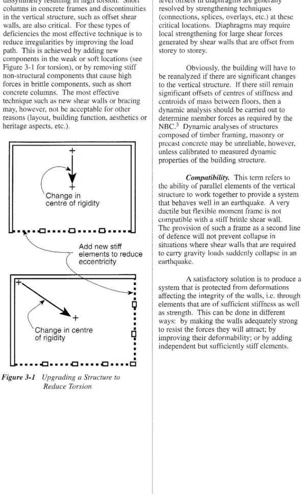
irregularities are soft or weak storeys and dissymmetry resulting in high torsion. Short columns in concrete frames and discontinuities in the vertical structure, such as offset shear walls, are also critical. For these types of deficiencies the most effective technique is to reduce irregularities by improving the load path. This is achieved by adding new components in the weak or soft locations (see Figure 3-1 for torsion), or by removing stiff non-structural components that cause high forces in brittle components, such as short concrete columns. The most effective technique such as new shear walls or bracing may, however, not be acceptable for other reasons (layout, building function, aesthetics or heritage aspects, etc.).
+
Lt
Change incentre of rigidity
.'\.oCI....
0 •••• 0 ••••セ Add new stiff
elements to reduce eccentricity
Irregularities such as setbacks in the vertical structure, re-entrant comers or split-level offsets in diaphragms are generally resolved by strengthening techniques (connections, splices, overlays, etc.) at these critical locations. Diaphragms may require local strengthening for large shear forces generated by shear walls that are offset from storey to storey.
Obviously, the building will have to be reanalyzed if there are significant changes to the vertical structure. If there still remain significant offsets of centres of stiffness and centroids of mass between floors, then a dynamic analysis should be carried out to determine member forces as required by the
NBC.3 Dynamic analyses of structures
composed of timber framing, masonry or precast concrete may be unreliable, however, unless calibrated to measured dynamic properties of the building structure.
Compatibility. This term refers to
the ability of parallel elements of the vertical structure to work together to provide a system that behaves well in an earthquake. A very ductile but flexible moment frame is not compatible with a stiff brittle shear wall. The provision of such a frame as a second line of defence will not prevent collapse in situations where shear walls that are required to carry gravity loads suddenly collapse in an earthquake.
A satisfactory solution is to produce a system that is protected from deformations affecting the integrity of the walls, i.e. through elements that are of sufficient stiffness as well as strength. This can be done in different ways: by making the walls adequately strong to resist the forces they will attract; by improving their deformability; or by adding independent but sufficiently stiff elements.
•
•
•
•
Q
•
•
•
•
o
•
•
•
•
•
• • • • .[J • • • • .[J • • • • .[J • • • •CJKセ
(ange in :entre
of rigidityFigure 3-1 Upgrading a Structure to Reduce Torsion
The consequences of adding new structural components to the existing structure are large local forces transmitted into existing materials. Careful attention should therefore be given to the transfer of forces into the existing components by suitable connection details.
Compatibility considerations also apply to overlays where there may be differential movements due to shrinkage, temperature and possibly creep.
Foundations. Foundation upgrading is usually expensive and, depending on the occupancy and use of the building, can be disruptive. Often it is possible to upgrade the building structure without upgrading the foundations, particularly in regions of low to medium seismicity.
One of the major disadvantages of new shear walls or bracing is that they may require new foundations. One way of avoiding or minimizing foundation upgrading for new shear walls or bracing is to incorporate the new walls or bracing within existing structural frames. Another is to install supplementary damping devices in the structure to reduce earthquake forces into the foundations.
Uplift of the foundations is often considered a deficiency which should be corrected, but in many cases this may not be necessary. The Guidelines for Seismic
EvaluationIdo not include anchorage to the foundations as a deficiency in low seismic zones. Whether or not uplift of the foundations is a serious deficiency depends on the amount of uplift and the damage that might occur as a consequence of this movement. In fact, foundation uplift may in some cases be considered as a positive feature, as discussed below under "System Behaviour."
Another way to avoid foundation upgrading is to use a longer length of shear wall or more bracing, especially in the lower floors. For example, long lengths of an existing wood wall could be used as a shear wall with only minor nailing and anchOling; such surfaces usually require a general architectural upgrade anyway.
System Behaviour. As in the seismic design of new structures, in the design of upgrading it is desirable to achieve a system behaviour with the following properties under seismic actions: composite action and fuse
behaviour.
The goal of composite action is achieved by adding new components in such a way as to make the existing and new
components act together compositely and to correct the deficiencies of the existing structure. For example, lack of integrity is corrected by providing new or improved connections. The provision of new components which stiffen the existing
structure, for example, helps prevent damage to brittle components such as unreinforced masonry.
The goal of fuse behaviour is achieved by making the structure perform in such a way that it 'yields' rather than 'fractures,' thereby preventing a progressive collapse. In assessing the effectiveness of fuse
behaviour; it is useful to follow the behaviour of the upgraded structure under increasing lateral load, and to establish a sequence of the failure modes in various components (yielding, buckling, rupture, uplift, etc.).
Base isolation and supplementary damping make use of the fuse concept, as does a ductile stable yielding failure mechanism in the beams of frames, in contrast to a brittle unstable failure mechanism in the columns. For the same reason, a rocking mechanism in masonry walls is preferred to a blittle shear failure. Similarly it is preferable to allow uplift at the base of concrete shear walls rather than permit sudden failure in shear or compression, particularly if the shear walls are brittle as is often the case in old buildings.
The degree to which the fuse concept can be relied on, however, depends on the resulting displacements and the consequential damage. Displacements can be estimated on the basis of NBC elastic seismic forces (not reduced by the R factor) combined with realistic stiffness values for the resisting elements of the structure.
GUIDELINE FOR SEISMIC UPGRADING OF BUILDING STRUCTURES
Damage Control. Control of damage
to non-structural building components and to building contents may be required for life-safety (falling components, blockage of exits), to protect investment, or to maintain building function following an earthquake. Damage control is therefore often a major consideration in the choice of upgrading techniques.
Anchorage of building components to the main structure is one technique for damage control. This Guideline restricts itself to anchorage and suppat1 of walls (non-structural as well as structural) and parapets.
Control of displacements of the structure (e.g., storey drift) to values which can be tolerated by non-structural components is another technique, as is reduction of seismic building accelerations (which might damage special machinery or artifacts) by special upgrading techniques such as base isolation or supplementary damping.
3.4.2 Other Considerations
Apart from concerns about structural safety and serviceability, there are other considerations that have a major impact on the choice of techniques and the design of details.
Accessibility. This refers to the ability
to gain access for the upgrading work, including the repair or replacement of building components and materials, the need for scaffolding, cranes, etc., and the ability to carry out the work in the available space. Difficult access is a major factor affecting upgrading techniques and cost. Foundations are the least accessible components of the structure and, as a consequence, usually the most costly to upgrade; techniques should therefore be sought to avoid foundation work.
Disruption. Disruption of the use and
occupancy of the building during the upgrading can be another major consideration if the building remains in operation during the upgrading. For this reason seismic upgrading of the building structure is best carried out dming a major renovation of the building, preferably when the building is unoccupied. In some cases this option is not available, and the upgrading must be carried out in stages, shifting people and operations around, undertaking work outside business hours, etc. In such cases, the duration of the disruption and its extent throughout the building becomes a major consideration in the choice of
upgrading techniques and the design of details. A special danger during upgrading is fire caused by welding sparks; precautions should be taken to prevent the occurrence of such fires.
Building Function. New structural
components, such as shear walls or bracing, can negatively affect layout (traffic flow), daylight or other features of the building which relate to its use. For this reason, moment frames may be preferable to shear walls in certain locations. Thick overlays such as concrete toppings increase floor elevation, requiring adjustments to stairs, doors, elevators, etc.
Aesthetics. Some upgrading
techniques are aesthetically unacceptable (see, for example, Figure 4-5). Cross-bracing can often have similar effects, and therefore moment frames are preferred in some locations, such as the front of a store. However, attention must be paid to stiffness considerations to avoid a soft-storey situation, resulting in large torsional displacements.
Heritage Values. Seismic upgrading of historic or unique buildings can be especially challenging. Heritage values are best served by the principle ofminimum structural intervention,where the existing building components/materials having heritage value are not substantially altered, or are altered in a way that respects and maintains the heritage value of the existing building. This often requires considerable attention to the design of details. Obviously the intervention must also comply with the objectives desclibed in 3.1 of life safety, damage control, and cost.
Such helitage concerns should therefore be addressed early in the choice of upgrading techniques and in the design of details in close cooperation with the architect, owner and conservation professional or organizations such as the Heritage
Conservation Program of Public Works and Government Services Canada.
Cost. The cost of seismic upgrading of an existing structure can be substantially higher than the cost for seismic resistance in a new structure. Cost can sometimes be reduced by using one technique to eliminate a number of deficiencies, or by choosing new structural components that make the new and existing components act compositely. Techniques that eliminate the need for foundation upgrading or ex'tensive structural upgrading can also be cost effective.
3.5
Design Criteria, Testing
of Special Devices
This Guideline does not contain specific requirements for upgrading, including structural design criteria, or requirements for the testing and maintenance of special devices. A major project in the U.S. (refelTed to as the ATC-33 project) is cUlTently
underway to develop specific requirements and criteria by 1997, and these may subsequently be adapted for Canadian practice. In the meantime the criteria spelled out in theGuidelines for Seismic Evaluation1
may be applied to establish the adequacy of the seismic upgrading. However, the reduction factor of 0.6 for evaluation contained in the Guidelines for Seismic Evaluationshould be increased to 1.0 for design of the upgrading, except in cases where it can be justified in terms of the objectives of this Guideline (risk to life, cost, damage control, heritage). Generally a more effective approach than reduced load factors is to catTy out a staged upgrading based on risk
mitigation and cost. More specifically, the following documents should be consulted for design criteria and testing of special devices: (1) For upgrading existing unreinforced
masonry bearing wall buildings, Appendix A of theGuidelines for Seismic
Evaluation.1
(2) For supplementary damping and base isolation, theNEHRP Recommended Provisions for Development of Seismic Regulations for New Buildings5in
conjunction with the CUlTent National Building Code and the relevant CSA standards6-9(see also Sections 5.1 and 5.2).
For foundations, the strength properties of most soils may be increased fo.r short term seismic forces, as recommended m theGuidelines for Seismic Evaluation.l
Chapter 4
Upgrading Techniques
Conventional
-Conventional seismic upgrading techniques include standard strengthening methods - placing connectors (anchors, nails, welds, bolts, dowels, splices, etc.) between existing structural components; connecting new components (members, overlays, infills) to existing components; building new sub-systems such as shear walls, bracing systems or piles and connecting them to the existing structure. Another conventional technique, not discussed in this chapter, is to remove one or more upper storeys of the building in order to reduce the seismic forces to a safe level. These strengthening methods make use of standard construction procedures. Techniques requiring specialized devices or materials, such as supplementary damping, base isolators and fibre-reinforced plastic or cement overlays are considered in Chapter 5. Techniques for
upgrading foundations are discussed in Chapter 6. This chapter provides brief descriptions of techniques that can be used for upgrading the building structure, including a discussion of their relative merits based on the objectives and principles described in Chapter 3.
The details shown in Figures 4-1 to 4-16 are generic and are intended to illustrate concepts. Each detail must be designed to be workable under the conditions that actually exist.
Care must be taken in the detailing to ensure that load paths are achieved. In general, the use of large gusset plates, long fillet welds or stitching with many anchors is
recommended to avoid concentrated forces at the interface of old and new components.
A global structural outlook must be maintained when developing an upgrade solution since an inappropriate solution may change the seismic characteristics of the building. For example, infilling a metal deck with concrete to increase its capacity will also increase gravity loads and possibly increase forces in some vertical elements because the diaphragm is much more rigid.
4.1
New Shear Walls,
Bracing or Moment
Frames
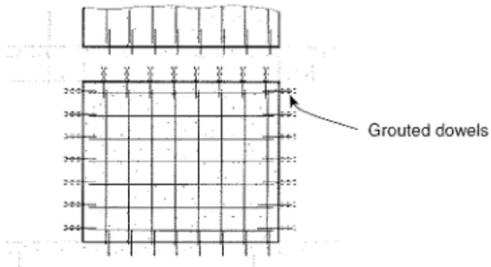
New shear walls may consist of reinforced concrete, reinforced masonry, plywood on studs, or steel. New bracing is generally steel but could be timber, and new moment frames are generally made of steel or reinforced concrete. These systems can be placed within the building, as interior or exterior walls or bracing (Figure 4-la, b), or outside the building as buttresses
(Figure 4-1 c). Exterior buttresses may have an advantage in that work can be cmTied out primarily from the outside, minimizing disruption and damage to interior finishes, equipment, etc.
Preferably, new shear walls or bracing should be continuous to the
foundations. Ifnot, the diaphragms may have
to be upgraded where vertical shear walls or bracing are offset between floors.
Choice of System: Itis generally best to choose a new system that is compatible with the existing structural system.
Compatibility in this Guideline usually refers to compatibility in the load-displacement response to a horizontal force. A new ductile moment frame, for example, is not compatible with an existing blittle shear wall. Ifthe new system is in the same line of resistance as an existing system, or between two similar existing systems joined by a rigid diaphragm, then the new and old systems are essentially parallel and should, preferably, be compatible. There is less need for compatibility if the stiff system is ductiie or if the incompatible systems are not acting in parallel.
GUIDELINE FOR SEISMIC UPGRADING OF BUILDING STRUCTURES
TGKKMMイMhMMKMKMMBABtBセ
Grouted dowelsa) New shear wall (reinforced concrete or masonry)
b) New bracing (HSS or double angles preferred)
Tie to suit existing conditions
Concrete, masonry or steel buttress wall Soil or rock anchors if required
C) External buttresses
Figure4-1. Nett' Shear Walls or Vertical Bracing
New moment frames or eccentric bracing are more compatible with existing moment frames and, if drift is not a problem, may be more effective and less costly,
especially if the structure is accessible from the inside, A problem to be considered with new steel moment frames in an existing facility is the difficulty of moving large beams within a confined space,
Location. Location of new shear
walls or bracing is a key decision which depends on non-structural as well as structural considerations,
Structural considerations in the location of new shear walls or bracing include the symmetry of the structure (torsional effects), the need for foundation upgrading, the need for new collectors/connectors for
transfelTing diaphragm shear into the new shear walls or bracing, and whether the horizontal diaphragm is flexible or rigid, Sometimes the latter is difficult to establish, in which case both assumptions should be considered,
d) New bracing (or shear walls) to reduce diaphragm sheaa
Earthquake forces due to irregularities such as torsion, or offsets in the vertical structure, can be substantially reduced by appropriate location of the new elements, Earthquake shear forces in the diaphragms can be reduced by adding new lines of lateral support as shown in Figure 4-1d,
Because foundation upgrading is usually expensive, it is desirable to try to make use of existing foundations by locating new shear walls or bracing within existing frames or to use light bracing instead of heavy shear walls, To reduce uplift and avoid upgrading of foundations, it is sometimes advantageous to lengthen bracing or shear walls so as to avoid
large overturning moments in one place, If
foundation upgrading is required, it may be better, however, to locate new shear walls or bracing away from existing foundations (inside or outside the building) because it is often easier to build new foundations than to upgrade existing ones,
Non-structural considerations affecting location include disruption if the building is to remain operational during upgrading, and the effects of the new shear walls or bracing on building function (layout, daylighting), building appearance and heritage value. For special service buildings such as hospitals, disruption can be a major problem and must be kept to an absolute minimum, for example by locating new shear walls or bracing outside the building. Occasionally these can conveniently be located within new additions to the building. Heritage
considerations, on the other hand, tend to require that new shear walls or bracing be placed unobtrusively inside the building. New shear walls or bracing can also create
obstructions to the functional use of the building and can affect the appearance of the building and its interior daylighting. However, concrete shear walls or buttresses can include fairly large openings provided they are properly designed. The location of new shear walls and bracing, therefore, must be worked out in close cooperation with the architect and the owner of the building.
Steel frames can be used as an exterior skeleton to transfer forces from the horizontal diaphragms to the foundations. When such frames are used, consideration must be given to maintenance; appropriate shapes should be used such as tubes or HSS sections with details that drain properly. Building secmity should also be considered as some an'angements of members may be easily climbable.
In summary, new shear walls or bracing should be considered especially where the existing building has the following deficiencies:
• Soft storeys • High torsion • High storey drifts • Pounding
• Masonry or other components sensitive to storey drift.
4.2
Upgrading Existing
Moment Frames
In medium to high seismic zones it is often more effective to incorporate new shear walls or bracing into existing frames than to upgrade existing moment frames. On the other hand, upgrading existing moment frames may be effective for low-rise buildings, especially if it avoids foundation upgrading and if the structure is easily accessible.
Conventional techniques for
upgrading existing moment frames include the following:
Steel Moment Frames:
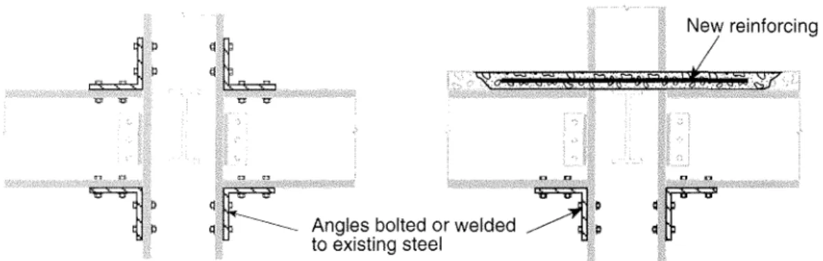
• Cover plates, clips and stiffeners (Figure 4-2)
• Gusset plates, knee braces • Reinforced concrete encasement
(Figure 4-3a)
• Steel jacketing (Figure 4-3b)
• Lateral bracing of unsupported flanges
Concrete Moment Frames:
• Steel jacketing (Figure 4-3b) • Reinforced concrete encasement,
(Figure 4-3a) or FRP encasement (Chapter 5)
• Repair of precast connections.
Steel moment frames are generally the easiest to upgrade, but if welding is used, it must be ensured that the existing steel is weldable. Recent earthquake experience with brittle failures at weld locations indicates that bolted connections may be preferable to welded connections. Reinforced and precast concrete frames are more difficult to upgrade, mainly because it is difficult to overcome deficient reinforcing or connection details.
Moment frames with existing infills of masonry require special attention. Because of the rigid infill, these systems act as shear walls and attract large forces. Failure can occur due to
• lateral instability of the infill,
• crushing or splitting of the infill due to large in-plane forces,
Angles bolted or welded to existing steel
GUIDELINE FOR SEISMIC UPGRADING OF BUILDING STRUCTURES
New reinforcing
Figure4-2. New or Improved Moment Connections
(a) Concrete encasement of columns
Ties
Cover removed ... セ . /
ャZゥ[LZZZ]]lッ]ョセァ]ゥエ]u]、Zゥョセ。]Q
]Zs[ZZZセjeG[セ[oァ
000"". , , /
'<>:<y:
reinforcement steel column
(b) Steel jacketing
Ties
セaョァャ・s
セキ・ャ、ウ
セsエイ。ーウ
Three upgrading strategies for infilled frames are:
(1) make the infill and frame act effectively as a shear wall (see Section 4.4),
(2) isolate the infill frame by means of gaps and resilient materials, while ensuring lateral stability of the infill,
(3) introduce new shear walls or bracing to stiffen the structure against infill damage while ensuring lateral stability of the infil!.
The first strategy is effective if the infilled walls have sufficient capacity, the second if the frames have sufficient capacity and drift is not a problem, and the third will remedy both deficiencies. Lateral stability of the infill is ensured by direct contact with the frame around its perimeter, by lateral supports at the top (see Figure 4-16b) or by wall mullions or basketing with plaster/wire mesh or FRC overlays (see Section 5.3).
Alternatively the infills can be replaced by other materials.
Ifan exterior wythe of masonry is located outside the frame, it may be vulnerable to delamination at the collar joint. Many brick masonry walls constructed of several wythes have inadequate connection (e.g., no headers or collar joints) between the wythes. This must be considered when developing an upgrade procedure.
4.3
Upgrading Existing
Braced Frames
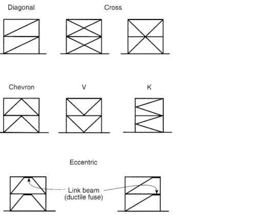
Existing braced frames are usually made of steel, but wood braced frames also occur. The types of steel bracing are shown in Figure 4-4. Cross-braced frames are most typical of older buildings, and theseカ。セ from flexible rod bracing (tension only) to stIff bracing which is strong in both compression and tension. Stiff cross-bracing that is
connected together where the bracing intersects generally exhibits ductile behaviourゥセ
earthquakes. Tension-only cross-bracmg exhibits poor behaviour because of yield elongation combined with 'slapping' of loose rods. Other types of bracing shown in Figure 4-4 include K bracing, and chevron or V-bracing, which also perform poorly compared to stiff cross-bracing. This is because compression buckling of a brace results in large unbalanced forces normal to the column or beam at the brace intersection. A new type of eccentric bracing has been developed which exhibits very ductile seismic behaviour. This bracing is discussed in 5.1.
Deficiencies most frequently found in existing braced frames are strength/ductility of the connections or members of the bracing system (including columns and beams), unfavourable type or configuration of the bracing system, and excessive drift in high seismic zones. Diagonal Cross Chevron
v
K Eccentricセlゥョォ「・。ュ
セ (ductile fuse)Figure4-4. Bracing Types
GUIDELINE FOR SEISMIC UPGRADING OF BUILDING STRUCTURES
Two upgrading strategies are: upgrade the existing bracing system, or add new bracing or shear walls. Both should be evaluated in terms of the objectives and principles described in Chapter 3.
For buildings more than three storeys in height, in medium to high seismic zones, consideration should be given to replacement of a tension-only bracing system by other means.
Conventional techniques for upgrading existing braced frames include:
• Strengthen or replace connections • Strengthen or replace members • Replace with better type of bracing
(Figure 4-1 b)
• Improve anchorage to the foundation The choice of technique will depend on accessibility and the bracing configuration: K-, V- or chevron bracing is sometimes difficult to strengthen and may have to be replaced by another type.
Wood bracing is sometimes difficult to upgrade and members that are severely checked have to be replaced. The ductility of wood bracing is governed by the connection details and often the greatest improvement is obtained by providing connections that result in ductile behaviour of the structure.
Infills (Reinforced concrete or masonry)
4.4
Upgrading Existing
Shear Walls
Four main types of shear walls are common in existing buildings: reinforced concrete or masonry, precast concrete, unreinforced masonry, and wood sheathing on studs. Behaviour varies considerably with type. Wood sheathing, reinforced concrete and reinforced masonry are the best performers, precast concrete less so, unreinforced brick or block masonry are relatively poor performers, while unreinforced hollow clay tile is the worst performer because of its friability.
Because new shear walls often need new foundations, increasing the
strength/ductility of existing shear walls is sometimes preferable. However, where large in'egularities exist in the building resulting in poor load transfer that produces high tors.ion, new walls or bracing may be more effectIve.
Conventional techniques for upgrading existing shear walls include:
Reinforced Concrete or Masonry:
• Infills (Figure 4-5)
Reinforced concrete overlays (Figure 4-6a) • Steel plating or bracing overlay
• Coupling beams • Post-tensioning
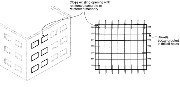
Close existing opening with reinforced concrete or reinforced masonry
n
,-, ,-,n
n n
n
n
:: :: '::: セ:C
'... Dowels .... :::' epoxy-grouted in drilled holes '... :::' '::: :::. '::: '*', '... ,....:' " '.' '.' '.' '.' '.' '.' '.' '.'Precast Concrete:
• Infills (Figure 4-5)
• Reinforced concrete overlays (Figure 4-6a) • Connection strengthening
• Pilasters/beams • Tie-downs
Unreinforced Masonry:
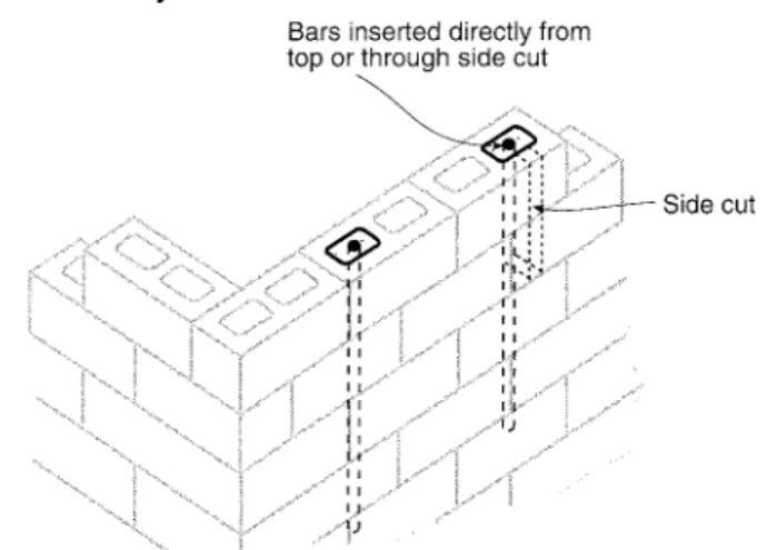
• Reinforced concrete overlays (Figure 4-6a) • Vertical reinforcing (Figure 4-7)
• Pilasters/columns
• Wire mesh/cement plaster or FRC • Replacement
Wood:
• Additional nailing
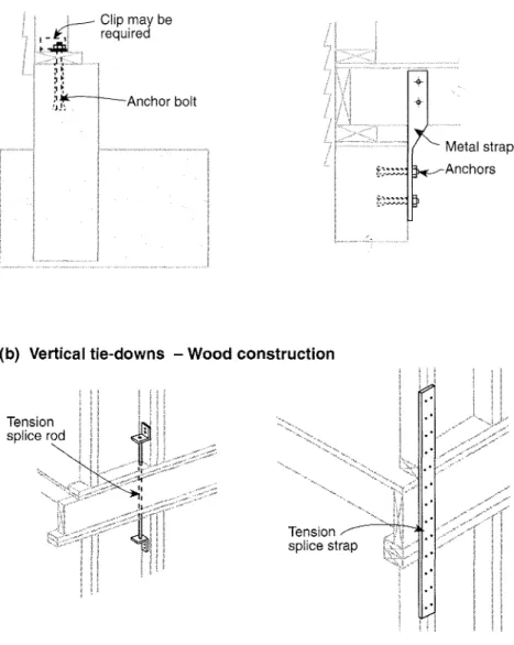
• Plywood/OSB overlays (Figure 4-6b) • Metal tie-downs and anchors (Figure 4-8)
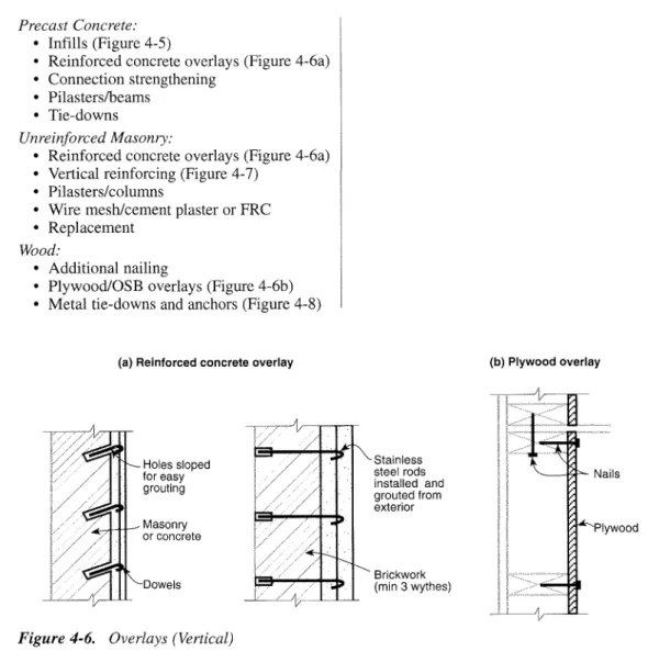
(a) Reinforced concrete overlay
Holes sloped for easy grouting Masonry or concrete Dowels
Figure4-6. Overlays (Vertical)
Stainless steel rods installed and grouted from exterior Brickwork (min 3 wythes) (b) Plywood overlay '--_*,,"--Nails Plywood
GUIDELINE FOR SEISMIC UPGRADING OF BUILDING STRUCTURES
(a) Block masonry
Bars inserted directly from
top or side cut
Nセ⦅MイM Side cut
(b) Brick masonry centre coring
Cored and grouted with rebars
(a) Foundation anchorage - Wood construction
I
,-
j...---Clip may berequiredit"" :>! .... ..' I """'Vi bolt ,... ... strap
(b) Vertical tie-downs - Wood construction
Tension splice strap Tension
splice
GUIDELINE FOR SEISMIC UPGRADING OF BUILDING STRUCTURES
Infills are often less costly, but they may be unacceptable for reasons of
appearance. Overlays are less disruptive if applied from the outside, but heritage or appearance considerations usually require them to be applied from the inside or on interior shear walls. Concrete overlays increase shear capacity and provide lateral support to existing masonry, but may require foundation
upgrading. Coupling beams between shear walls which behave in a ductile manner may sometimes be cost-effective because they not only reduce wall overturning forces but improve the overall ductility of the connected system. Consideration should be given to the effects of relative movements between new overlays/infills and existing shear walls, e.g., shrinkage cracks and bowing.
The continuity of the shear wall system should be ensured by providing a continuous load path in shear, tension and compression. Existing concrete walls deficient in zone reinforcement can be upgraded by adding concrete nibs or bolting on steel members. Foundation tie-downs for precast walls to convert them into vertical cantilevers or additional shear transfer connections may be used as alternatives to strengthening existing connections. Tie-down splices and shear transfer connections may be required in wood shear walls, particularly for shorter walls, whereas longer wood-stud shear walls may not require tie-downs.
Concrete block walls can be upgraded for both in-plane and out-of-plane forces by the installation of vertical reinforcement in the hollow cores (Figure 4-7a). The concrete in the roof bond beam is chipped out and a reinforcing bar is inserted and anchored to the foundation by a grout-filled hole.
Alternatively, hollow cores may be opened by saw-cuts near the top of each storey for inserting reinforcing bars. The reinforced core is then filled with concrete. If intermediate bond beams exist, they are carefully chipped out locally. An advantage of this procedure is that work can be carried out from the exterior, Though the exterior face exhibits some patching, it is usually covered with an air barrier, insulation and a new finish. A similar technique is used for brick masonry (minimum thickness 300 mm) by drilling vertical cores (l00 mm diameter) down through the masonry and placing reinforcing steel and grout (polymer cement) in the cored holes
(Figure 4-7b). The technique provides greater lateral stability and better rocking resistance of narrow walls. For both methods the
reinforcing may be post-tensioned.
Alternatively, unreinforced masonry can be upgraded by fibre-reinforced plasters (see 5.3) and by reinforced concrete overlays, including the option of removing the outer wythe to reduce weight and space.
4.5
Upgrading Existing
Diaphragms
Existing diaphragms are generally a probl.em only for medium to high seismicity locatIOns; however, transfer of shear from the diaphragm into the vertical structure may be a
ーイッ「ャセュ in lower seismic zones. Earthquake
expenence shows that most diaphragm failures are connection failures rather than failure of the diaphragm itself.
Two main types of diaphragms are common: flexible diaphragms consisting of wood or metal decking, and rigid diaphragms such as concrete slabs, concrete-filled metal decks, or floor structures which are
horizontally braced. Rigid diaphragms transfer inertial storey forces to the vertical structure according to the relative stiffness of the vertical components. Flexible diaphragms tend to behave as beams between lateral supports and transfer inertial storey forces to the lateral supports. In high seismic zones, flexible
_ゥ。ーセイ。ァュウ may deform excessively, resulting
m failure of masonry walls (see Appendix A of
Guidelines for Seismic Evaluation1).
Diaphragms act as horizontal beams in both bending and shear. Itis therefore
ゥュセッイエ。ョエ that the integrity of the diaphragm be
achIeved. Integrity is achieved by the use of
」ッセエゥョオッオウ chords or ties near the perimeter,
splIces or reinforcing at re-entrant comers, and collectors to transfer shears from the
diaphragm into the vertical structure. Conventional techniques for upgrading existing diaphragms include:
Timber Diaphragms:
• Nailing, stapling of existing diaphragms Plywood overlay (Figure 4-9a)
• Cross-walls (see Appendix A of Guidelines
for Seismic Evaluation1)
• Nailing, bolting for shear transfer (Figure 4-12)
• Spliceslblocking for chords, collectors (Figures 4-12, 4-14)
• New chords, collectors
Steel Deck Diaphragms:
• Welding
• Reinforced concrete overlay (Figure 4-9b) Steel bracing (Figure 4-10)
• Shear studs, anchor bolts, dowels for shear transfer (Figure 4-11)
• Steel chords, framing (Figure 4-11)
Steel-Braced Diaphragms:
• Replacement, reinforcement or addition of members or connections
• Secondary bracing
• Steel deck and/or reinforced concrete overlay with shear studs (Figure 4-9b)
Concrete Diaphragms:
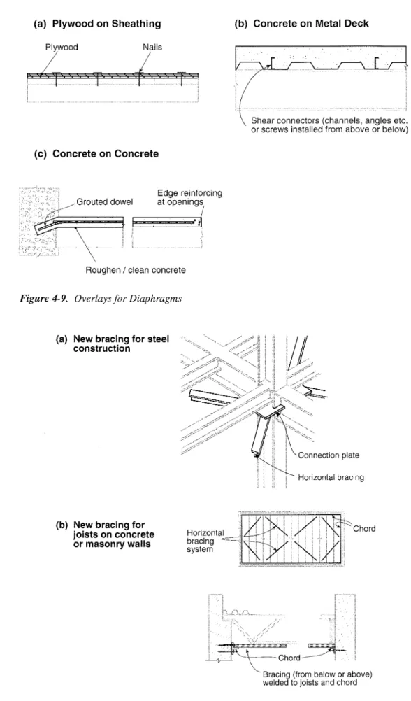
• Reinforced concrete overlay (Figure 4-9c) Opening infills
• Additional dowels for shear transfer (Figures 4-9c, 4-13)
• Collectors under the diaphragms
• New chords, framing (Figures 4-13, 4-14)
Itis usually more economical to upgrade wood roof diaphragms from above rather than by installation of bracing or plywood from below. This is because work from below may interfere with mechanical, electrical, sprinkler and architectural systems. On the other hand, it is sometimes more economical to upgrade steel deck diaphragms from below by the addition of horizontal bracing.
Cost and disruption are determined to a large extent by accessibility (removal and replacement of non-structural components such as flooring and partitions) and the extent of floor area requiring alteration. Reinforced
セッョ」イ・エ・ toppings have the disadvantages of
mcreased floor elevation (requiring changes to stairs, doors, etc.), increased dead load, and sometimes increased torsion associated with stiff diaphragms.
Substantial upgrading of the diaphragm can sometimes be avoided by introducing additional vertical shear walls or bracing (see 4.1).
GUIDELINE FOR SEISMIC UPGRADING OF BUILDING STRUCTURES
(a) Plywood on Sheathing (b) Concrete on Metal Deck
rl°
Od NailstセN セセ
Shear connectors (channels, angles etc. or screws installed fromaboveor below)
(c) Concrete on Concrete Grouted dowel Edge reinforcing at openings
/
NセRoughen / clean concrete Figure4-9. Overlays for Diaphragms
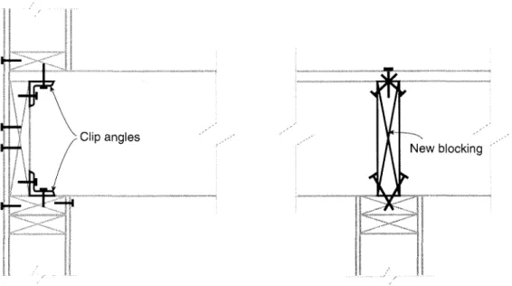
(a) New bracing for steel construction
(b) New bracing for joists on concrete or masonry walls hッイゥコッョエ。セLi]セZエャj bracing セ system Horizontal bracing Chord
Bracing (from below orabove)
welded to joists and chord Figure 4-10. Bracing for Diaphragms
New chord and anchor
angle (collector)
セ
Steel strap anchored to deck/chordWelds to strap and deck, as required Steel angle anchored to ledger/wall, as required
Figure4-11. Shear Transfer and Chords (Metal Deck Diaphragms)
plate and anchor
Clip angles
Figure4-12. Shear Transfer and Chords (Wood Diaphragms)
Masonry Precast slab Chord Increased for shear transfer Concrete Precast slat
GUIDELINE FOR SEISMIC UPGRADING OF BUILDING STRUCTURES
(a) Collector in wood diaphragm
Collector be required directions) (b) Reinforcing an opening "
:::..£-IA
:: :
iiiセ I I I - - - -I It- - - セi I- - -====:=: - - - -
,,(1-セ ==::: I I I I I I I I r I I I I I I I r I I I I I I I I I I I I I I I I I I I ====.=t _ _ _ _ _ _ _ __ _ _ _ :::J===:::-- -1
ゥセ
--- -- ----
MLセ
Welds I II ILl- ' Section A-ASteel angle or strap
(c) Splicing a glulam beam
4.6
Techniques for Lateral
Support of Walls and
Parapets
Lack of wall anchorage and slender unsupported parapets are the most prevalent life-threatening structural deficiencies in existing buildings. Upgrading for these deficiencies is generally much less costly and less disruptive than for other deficiencies of the building structure.
Both load-bearing and non-load-bearing walls should be addressed. Unbraced masonry and wood-stud partitions are common along egress routes. These partitions may support ceilings and other non-structural elements.
Typical clip angle tie
RRPュゥョセO
i1/ '.• ...••...•.:.·....•.
i•.•. ••...••. Alternate anchorage1. __ / //
.-><>.-/__OMOZMMセ
Anchor bolt (check for shear) Chord angle
Steel strap welded to chord
Blocking
Figure 4-15. Lateral Support of Exterior Walls
Techniques for anchorage or lateral support of walls and parapets are relatively simple, but care must be taken to ensure that details are designed for load transfer and that the work is properly carried out. For example, connections that depend on tension
perpendicular to the grain in wood components connecting the anchor to the diaphragm must be avoided. Another common problem arises when lateral supports of the top of a wall do not permit vertical deflection of the structure above, thereby creating a load-bearing wall.
Conventional techniques for lateral support of walls and parapets include:
Exterior Masonry/Concrete Walls:
• Anchor bolts (Figures 4-11, 4-13, 4-15) • Grouted dowels (Figures 4-9c, 4-13) • Overlays (Figure 4-6a) or back-up walls
Blocking
+ + + +
Metal strap anchor Through rod Concrete or masonry Flooring Sleeve nut Joist Grouted anchor
GUIDELINE FOR SEISMIC UPGRADING OF BUILDING STRUCTURES
Exterior Curtain Walls:
• Connectors which allow racking
Masol1l)' Parapets and Other Appendages:
• Bracing and anchoring (Figure 4-16a) • Reduction in parapet height
Veneers:
• Veneer anchors
Partitions:
• Lateral supports (Figure 4-16b) • Overlays or back-up walls
Smaller, more numerous anchors rather than large anchors spaced far apart are preferred to achieve a ductile type of failure.
To minimize disruption, anchorage of exterior walls should preferably be caniect out from the outside. Work will have to be carried out from the inside where the exterior is inaccessible or where the appearance of the anchors is unacceptable.
In many cases it is necessary to upgrade not only the connections but also to consider deficiencies of the wall itself. For example, unreinforced masonry walls may require the additional support that is provided by vertical reinforcing (Figure 4-7), overlays (Figure 4-6a) or beam/column back-ups.
Anchor
Channel anchored to parapet Brace
(a) Masonry parapet support
(b) Masonry partitions
Steel angle Gap
Steel Twith vertical siot
Chapter 5
Upgrading Techniques • Special
This chapter provides guidance onthree innovative upgrading techniques: supplemental damping, base isolation, and
FRPIFRC overlays. Italso references
procedures for evaluating buildings that incorporate special damping and isolation devices. These techniques and devices are relatively new and in various stages of development. Therefore the guidance is, to a large extent, qualitative and the collaboration of specialist consultants may be required.
References for more detailed information are given for each special technique.
5.1
Supplemental Damping
Itis well known that inelastic structural behaviour dissipates seismic energy that is fed into the building structure. As a consequence, the design lateral forces for which the structure must be designed are reduced. The NBC accounts for this by the force modification factor R which ranges from
I to 4; the higher the factor the better the energy dissipation. In addition to energy dissipation due to inelastic structural
behaviour, energy is also dissipated as a result of inelastic deformation of non-structural building components and by sliding friction between these components. Such energy dissipation is taken into account in the evaluation criteria for unreinforced masonry buildings (Appendix A of Guidelines for
Seismic Evaluation1) arising from inelastic
action of the wood diaphragms and partitions. Supplemental damping devices can be inserted in a building to reduce the dynamic response by removing much of the energy induced in the structure by an earthquake. When appropriately installed, these devices allow seismic design to be shifted from the conventional reliance on ductility of the main structural elements to energy dissipation in the added devices. The devices help protect the building from severe damage or collapse by limiting resonance build-up and consequently reducing inelastic deformation of the structure.
The consequence of incorporating supplementary damping devices is reduced dynamic amplification of earthquake ground motions in the building, in particular reduced interstorey displacements as compared to those that would occur without the devices.
If,however, the existing structure is laterally very stiff (e.g. a shear wall) and brittle, then it is generally not possible for the devices to work sufficiently to reduce damage to the building. Ifthe structure is laterally flexible (e.g. a moment frame), then the devices can work effectively to substantially reduce the interstorey displacement that would otherwise occur during the earthquake, resulting in less
damage to the building. If,however, there are
stiff and brittle infills attached to a flexible structure, they will act as brittle shear walls and fail before the devices work effectively. Stiff infills or panels should therefore be either detailed to allow interstorey drift, or, if they are strong enough, be attached to the structure with damping devices in order to contribute to the energy dissipation.
A number of buildings in Canada, the United States, Japan, Mexico, and other countries have recently been seismically upgraded with such devices. One of the principal benefits of this type of retrofit is avoidance of the need for foundation upgrading. The damping devices are usually incorporated into new or existing bracing of the structure, in connections between non-structural panels and the structure, or at other locations where relative movements will occur during an earthquake.