HAL Id: tel-01753063
https://hal.univ-lorraine.fr/tel-01753063
Submitted on 29 Mar 2018
HAL is a multi-disciplinary open access archive for the deposit and dissemination of sci-entific research documents, whether they are pub-lished or not. The documents may come from teaching and research institutions in France or abroad, or from public or private research centers.
L’archive ouverte pluridisciplinaire HAL, est destinée au dépôt et à la diffusion de documents scientifiques de niveau recherche, publiés ou non, émanant des établissements d’enseignement et de recherche français ou étrangers, des laboratoires publics ou privés.
synthesis of polystyrene and polyamide graft copolymers
and compatibilizing efficiency of these copolymers
Cai-Liang Zhang
To cite this version:
Cai-Liang Zhang. Réactive and polymer blending process : controlled synthesis of polystyrene and polyamide graft copolymers and compatibilizing efficiency of these copolymers. Other. Institut Na-tional Polytechnique de Lorraine, 2008. English. �NNT : 2008INPL067N�. �tel-01753063�
AVERTISSEMENT
Ce document est le fruit d'un long travail approuvé par le jury de
soutenance et mis à disposition de l'ensemble de la
communauté universitaire élargie.
Il est soumis à la propriété intellectuelle de l'auteur. Ceci
implique une obligation de citation et de référencement lors de
l’utilisation de ce document.
D'autre part, toute contrefaçon, plagiat, reproduction illicite
encourt une poursuite pénale.
Contact : ddoc-theses-contact@univ-lorraine.fr
LIENS
Code de la Propriété Intellectuelle. articles L 122. 4
Code de la Propriété Intellectuelle. articles L 335.2- L 335.10
http://www.cfcopies.com/V2/leg/leg_droi.php
en co-tutelle avec Zhejiang University
Industries Chimiques (ENSIC) Ecole Doctorale
Ressources Procédés Produits Environnement (RP2E)
Laboratoire des Sciences du Génie Chimique (LSGC-CNRS UPR 6811)
Procédés d’extrusion réactive et de mélange de polymères :
Synthèse contrôlée de copolymères greffés à base de
polystyrène et de polyamide ; et étude de l’efficacité de
compatibilisation de ces copolymères
THESE
présentée en vue de l’obtention du
DOCTORAT DE L’INSTITUT NATIONAL POLYTECHNIQUE DE LORRAINE
Spécialité : Génie des Procédés et des Produits par
Cai-Liang ZHANG
Master en Génie des Procédés
Zhejiang Université, Hangzhou, Chine
Soutenance prévue le 10 novembre 2008 à 9h
Composition du jury :
Rapporteurs : M. Luc AVEROUS M. Ming-Qiang ZHONG
Professeur (Université de Strasbourg) Professeur (Zhejiang University of Technology, Chine)
Examinateurs : M. Guo-Hua HU
M. Lian-Fang FENG
Professeur (Nancy-Université, INPL) et membre de l’IUF
First and foremost I would like to express my gratitude to my advisors Dr. Guo-Hua HU and Dr. Lian-Fang FENG. Besides their creactive ideas of research, continuous guidance and inspiring discussion, their consistently encouraging and supporting to my study and research have been the key to the success of my Ph.D. I am thankful to them for providing me with a great research environment, resources, advice, and flexibility in my work. From them I have also learnt more than just how to do good research. Special thanks are given Dr. Sandrine HOPPE, Xue-Ping GU and Dr. Jia-Jun WANG for providing helps and suggestions for this study.
I am thankful to my mates both in Chinese and French research group — Guang-Zan LI, Xian-Ming ZHANG, Yu-Hua XUE, Jing CHANG, Jian ZHAO, Feng-Yong LI, Wen-Feng ZHANG, Xiao-Bo SONG, Sha-Sha CUI, Jin-Xia Li, Chao ZHAO, Yan-Fei TANG, Zheng-Hui LI, Fang SHAO, Guo-Long JI, Shan-Shan DAI, Jing-Gang GAI, Christian PENU, Jean-Marie BOISSIERE, Marina MAGATON, Ahmed BHRAN, Jonathan LEBLANC who helped in varying ways to understand some of the fascinating science of polymers. Of all these names, Jian ZHAO deserves a special mention, who has participated in the research work about the efficiency of graft copolymer at stabilizing the co-continuous phase. I would like to express my great appreciation to Tao-Tao FU, Dong AN, Yuan FANG who have contributed to my wonderful life in France.
This research would not have been possible finished without the generous financial support of the National Natural Science Foundation of China (grant numbers 50390097 and 20310285), the Ministry of Science and Technology of China through an international cooperation program (grant number: 2001CB711203), and the Association Franco-Chinoise pour la Recherche Scientifique et Technique-AFCRST (grant number: PRA Mx02-07). I would like to thank China Scholarship Council for supporting my study in France.
The completion of this thesis would not have been possible without the support of my family. I owe a debt of gratitude to my parents for their patience and understanding. I will give my final note of thanks to my wife, Ling-Li HU. Her love, constant understanding and encouraging and sharing every feeling are the ultimate support to the success of this thesis.
Abstract
Polymer blending offers an important route to new materials with combinations of properties not available in constituent polymers. Most polymer pairs are immiscible, leading to phase separation at equilibrium and yield a material with poor properties. To address this challenge, block or graft copolymers pre-made or generated in-situ by reactive blending are often used as compatibilizers. Most studies are focused on the compatibilizing efficiency of block copolymers and few studies address that of graft copolymers, partly because of difficulties of controlling their molecular structures.
This thesis is devoted to the study of the emulsification efficiency of graft copolymers. It is composed of three parts: (1) development of a novel reactive extrusion process for synthesizing graft copolymers with polystyrene (PS) as backbone and polyamide 6 (PA6) as grafts; (2) emulsification efficiency of PS-g-PA6 graft copolymers for PS/PA6 blends; and (3) concept of tracer-emulsifier.
The underlying chemistry for the synthesis of PS-g-PA6 graft copolymers was based on the use of a copolymer of styrene (St) and 3-isopropenyl-α, α-dimethylbenzene isocyanate (TMI), PS-co-TMI, to activate/e the polymerization of ε-caprolactam (CL) in the presence of sodium ε-caprolactam (NaCL) as an anionic catalyst. The structure of a graft copolymer is mainly determined by the following three parameters: backbone length, graft density, and graft chain length. The backbone length of the PS-g-PA6 depended only on the molar mass of the initial PS-co-TMI and the PA6 graft density was dictated by the TMI content in PS-co-TMI.
The efficiency of graft copolymers at compatibilizing the dispersed phase/matrix morphology of PS and PA6 blends and stabilizing the co-continuous morphology of the blends during quiescent annealing were studied. Results showed that for graft copolymers with similar backbone and graft density, the longer the grafts, the higher their efficiency. For a given backbone/graft composition, graft copolymers having fewer and longer grafts were more efficient at comaptibilizing and stabilizing the morphology.
Feeding mode had a very significant effect on the size of the dispersed phase domains at short mixing time and its effect decreased or became negligible at long mixing time. This indicates that feeding mode affected mostly the time necessary for the PS-g-PA6 compatibilizer to reach and emulsify the interfaces between PS and PA6. A good feeding mode should meet the following two requirements: first, the matrix should melt faster than the dispersed phase in order to avoid the phase inversion;
second, the compatibilizer should be present as soon as the blending process starts, namely, the dispersed phase begins to melt.
Building up an emulsification curve may not always be practical because of limited amounts of copolymers available. This is especially true for an industrial polymer blending process. A so-called concept of emulsifier-tracer was developed to solve the problem. Very small amounts of fluorecent moities such as anthracene were incorporated in PS-co-TMI. When the latter was used to activate the polymerization of CL, the resulting PS-g-PA6 graft copolymer contained fluorescent moities. An original method for constructing the emulsification curve of a polymer blend in a continuous mixer such as a twin-screw extruder was developed based on the tracer-emulsifier concentration distribution (i.e. the residence time distribution) and the corresponding dispersed phase domain size distribution of the blend system. The resulting emulsification curves exhibited unique features that would open a new research field for polymer blending.
Résumé
Les mélanges de polymères ouvrent une importante voie à l’obtention de nouveaux matériaux dont les propriétés peuvent être très différentes de celles de chacun des constituants des mélanges. La plupart des polymères sont immiscibles. Ainsi leurs mélanges constituent des phases distinctes et les propriétés de ces mélanges sont souvent médiocres. Afin de relever ce défi, copolymères à bloc ou greffés synthétisés séparément ou générés in-situ lors du procédé de mélanges sont souvent utilisés en tant que agents compatibilisants. Beaucoup d’études ont porté sur l’efficacité de compatibilisation de copolymères à bloc et peu d’études sur celle de copolymères greffés, en partie en raison des difficultés dans le contrôle de leurs structures moléculaires.
Cette thèse porte sur l’étude de l’efficacité d’émulsification de copolymères greffés. Elle est composée de trois parties : (1) développement d’un nouveau procédé d’extrusion réactive pour la synthèse de copolymères greffés avec polystyrène (PS) comme squelette et polyamide 6 (PA6) comme greffons ; (2) efficacité d’émulsification du copolymère greffé, PS-g-PA6 pour les mélanges à base de PS et PA6 ; et (3) développement d’un nouveau concept dit d’agent émulsifiant – traceur.
La chimie de synthèse mise en jeu de copolymères greffés de PS-g-PA6 était basée sur l’utilisation d’un copolymère de styrène (St) et d’isocyanate de 3-isopropenyl-α, α-dimethylbenzène (TMI), PS-co-TMI, pour activer la polymérisation de l’ε-caprolactame (CL) en présence d’ε-caprolactame de sodium (NaCL) en tant que catalyseur anionique. La structure du copolymère greffé ainsi formé est caractérisée par les trois paramètres suivants : longueur du squelette, densité des greffons et longueur des greffons.
Au niveau de l’efficacité de copolymères greffés PS-g-PA6 pour compatibiliser les mélanges PS/PA6 de type morphologie phase dispersée /matrice lors du procédé de mélange ou stabiliser ces mélanges de type morphologie co-continue en état statique, il a été montré que pour des copolymères greffés ayant le même squelette et le même nombre de greffons par squelette, plus les greffons sont longs, meilleure l’efficacité. D’autre part, pour une composition massique squelette/greffons donnée, les copolymères greffés ayant moins de greffons par squelette mais avec des greffons plus longs ont une plus grande efficacité de compatibilisation ou stabilisation.
Le mode d’alimentation du copolymère greffé a eu un impact significatif sur la taille des domaines de la phase dispersée pour des temps de mélange courts et cet
impact devient négligeable à temps de mélange longs. Ceci montre que le mode d’alimentation de l’agent compatibilisant influe sur le temps nécessaire pour qu’il atteigne et émulsifie les interfaces entre le PS et le PA6. Il est préconisé qu’un bon mode d’alimentation satisfasse les deux conditions suivantes : tout d’abord, la matrice doit fondre plus rapidement que la phase disperse afin d’éviter l’inversion de phases ; en deuxième lieu, l’agent compatibilisant doit être présent dans le système de mélange dès que le procédé de mélange est mis en route, autrement dit, dès que la phase dispersée commence à fondre.
Il n’est pas toujours possible de construire une courbe d’émulsification en raison des quantités de copolymères disponibles. Ceci est d’autant plus vrai pour un procédé de mélange industriel. Un concept d’compatibilisant – traceur a donc été proposé. De très faibles quantités d’entités fluorescents tells qu’anthracène sont incorporés dans le PS-co-TMI. Lorsque ce dernier est utilisé pour activer la polymérisation du CL, le copolymère greffé PS-g-PA6 obtenu contient des entités fluorescentes. Une technique originale a donc été développée permettant de construire une courbe d’émulsification pour des mélanges de polymères élaborés dans un mélangeur continu de type extrudeuse bi-vis. Elle est basée sur la la distribution de la concentration en compatibilisant-traceur (c’est-à-dire, la distribution des temps de séjour) et celle de la taille des domaines de la phase dispersée du mélange de polymères correspondante. La courbe d’émulsification ainsi obtenue présente des caractéristiques très intéressantes ouvrant un nouveau champ d’étude dans le domaine des mélanges de polymères.
Mots clés : Procédé d’extrusion réactive ; copolymère greffé ; mélange de polymères ;
Table of contents
Acknowledgments... I Abstract ...II Résumé ... IV
Chapter 1 Introduction ...1
1.1 Motivation and objectives...1
1.2 Overview of thesis...2
Chapter 2 A novel reactive extrusion process for the synthesis of PS-g-PA6 graft copolymers...4
2.1 Introduction ...4
2.1.1 Synthesis methods of graft copolymer ...4
2.1.2 Graft copolymer formation by reactive blending ...7
2.2 Study object and strategy ... 11
2.3 Mechanism of the graft copolymer PS-g-PA6 formation ...12
2.4 Experimental...14
2.4.1 Material ...14
2.4.2 Synthesis of PS-co-TMI...14
2.4.3 Synthesis of PS-g-PA6 graft copolymer and homopolymer PA6 ...15
2.4.4 Methods used for the determination of the CL conversion ...16
2.4.5 Purification and fractionation of polymerized products...18
2.4.6 Determination of the characterization of Homo-PA6 and PS-g-PA6 by SEC ...19
2.4.7 FTIR analysis ...20
2.4.8 NMR spectroscopy...20
2.4.9 DSC measurements ...20
2.5 Comparison of various methods of measuring the conversion of CL to PA6 ...21
2.5.1 Effect of the pre-drying of polymerized product films ...21
2.5.2 Performances of the various methods of measuring the CL conversion for grafting polymerization system ...23
2.5.3 Suitability of the above methods for the anionic homopolymerization system...30
2.5.4 Summary ...32
2.6 Characterization of PS-g-PA6 by SEC at room temperature ...33
2.6.1 Choice of co-solvents for the N-trifluoracetylation reaction...34
2.6.2 Characterization of the N-trifluoroacetylation reaction...37
2.6.3 Measurement of the molar mass of PS-g-PA6 by SEC ...40
2.6.4 SEC measurement of the composition of PS-g-PA6 ...43
2.6.5 Summary ...48
2.7 PS-co-TMI characterization ...48
2.7.1 Molar mass...48
2.8 Evaluation of as-synthesized graft copolymer ...51
2.8.1 Composition of as-polymerized products ...51
2.8.2 Composition of pure PS-g-PA6...56
2.8.3 Melting and recrystallization behavior of pure PS-g-PA6...59
2.9 Kinetics of the anionic polymerization of CL from PS-co-TMI...60
2.9.1 Relationship between conversion and torque...60
2.9.2 Effect of the set temperature on the polymerization ...61
2.9.3 Effect of NaCL/CL...63
2.9.4 Effect of the NCO/CL molar ratio...65
2.9.5 Effect of feeding mode...69
2.10 Conclusions ...71
Chapter 3 Degradation of PS-g-PA6 graft copolymer ...74
3.1 Introduction ...74
3.2 Experimental...75
3.2.1 Treatment in formic acid ...75
3.2.2 Static annealing and mixing ...75
3.2.3 TEM microscopy...75
3.3 Results and discussion ...75
3.3.1 Degradation in the process of formic acid extraction...75
3.3.2 Degradation in high temperature and high shear...84
3.4 Conclusions ...92
Chapter 4 Compatibilization efficiency of graft copolymers for immiscible polymer blends...94
4.1 Introduction ...94
4.2 Experimental...97
4.2.1 Blending process ...97
4.2.2 Rheological characterization...97
4.2.3 Characterization of blend morphologies ...97
4.3 Results and discussion ...98
4.3.1 Rheology ...98
4.3.2 Effect of PS-g-PA6 graft copolymer for PS/PA6 (20/80) blend system ...98
4.3.3 Effect of PS-g-PA6 graft copolymer for PS/PA6 (80/20) blend system ...101
4.3.4 Comparison of two blend systems ...103
4.4 Conclusions ...107
Chapter 5 Efficiency of graft copolymers at stabilizing co-continuous polymer blends during quiescent annealing ...109
5.1 Introduction ...109
5.2 Experimental... 111
5.2.1 Blend preparation... 111
5.2.3 Solvent extraction ... 111
5.2.4 Mercury intrusion porosimetry ... 111
5.3 Results and Discussion ... 112
5.3.1 Rheology ... 112
5.3.2 Annealing of blend systems without PS-g-PA6... 112
5.3.3 Annealing of polymer blends with PS-g-PA6 ... 115
5.4 Conclusions ...120
Chapter 6 Effect of feeding mode on the morphologies of immiscible polymer blends...122
6.1 Introduction ...122
6.2 Experimental...123
6.2.1 Blending process ...123
6.3 Results and discussion ...124
6.4 Conclusions ...129
Chapter 7 Preparation of tracer-emulsifier and comparison of RTD and DSD in TSE...130
7.1 Introduction ...130
7.2 Basic principles of the preparation of tracer-emulsifier...132
7.3 Experimental...133
7.3.1 Synthesis of the tracer-emulsifier...133
7.3.2 Extruder, screw configurations and instrumentation...133
7.3.3 Measurement Procedure...134
7.3.4 SEC measurements ...135
7.4 Results and discussion ...135
7.4.1 PS-co-TMI-MAMA ...135
7.4.2 Tracer-emulsifier ...136
7.4.3 Mass of tracer-emulsifier for one experiment in twin screw extruder...139
7.4.4 Comparability of RTD and DSD in different conditions...141
7.4.5 DSD in different time domains ...147
7.5 Conclusions ...149
Chapter 8 General conclusion and future work...151
8.1 General conclusion...151
8.2 Future work...154
Appendix ...156
List of Figures
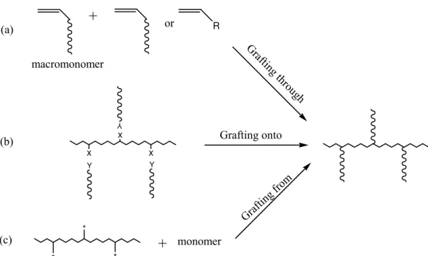
Figure 2.1 Scheme of three methods for the synthesis of graft copolymers: (a)
“grafting through”, (b) “grafting onto” (X and Y are the pendant functional groups of the backbone and the end-functional groups of grafts, respectively), (c) “grafting from” (* is an initiating group)...5
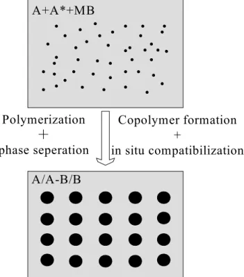
Figure 2.2 Schematic description of the in-situ polymerization and in-situ
compatibilization. A* denotes polymer A chains bore initiating sites either at the chain end(s) or along the chain backbones. ...10
Figure 2.3 Synthesis of PS-co-TMI and anionic polymerisation of CL from
PS-co-TMI in the presence of NaCL as a catalyst. ...13
Figure 2.4 TGA diagrams of a typical product obtained by the anionic grafting
polymerization of CL onto PS-co-TMI. (a) Accumulated mass loss as a function of temperature increase; (b) Instantaneous mass loss as a function of temperature increase. ...18
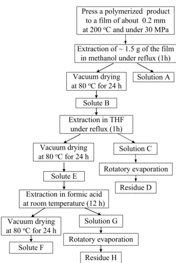
Figure 2.5 Procedure used for the purification and fractionation of polymerized
products...19
Figure 2.6 Effect of the pre-drying in a vacuum oven at 50 °C for 12 h on the
TGA diagrams of the polymerised product of the experiment E14. (a) Accumulated mass loss as a function of temperature increase; (b) Instantaneous mass loss as a function of temperature increase. ...22
Figure 2.7 FTIR spectra of PS-co-TMI4, PS-co-TMI4-CL and residue D from
the polymerized product of E5...24
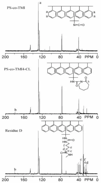
Figure 2.8 13C NMR spectra of PS-co-TMI, PS-co-TMI4-CL and residue D from the as-polymerized product of E5. ...24
Figure 2.9 UV spectra of (a) PS-co-TMI in THF and (b) solution C from the
as-polymerized product of E5. . ...25
Figure 2.10 Procedure used for evaluating the performance of water and
methanol as solvent for extraction. ...26
Figure 2.11 UV spectra of (a) the solution of CL, (b) solution A and (c) solution
L. ...26
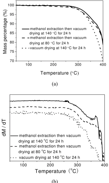
Figure 2.12 TGA traces of the polymerized product E5 subjected to one of the
following treatments: (1) methanol extraction then vacuum drying at 140 ºC for 24 h; (2) methanol extraction then vacuum drying at 80 °C for 24 h and (3) vacuum drying at 140 ºC for 24 h. (a) remaining mass percentage; (b) instantaneous loss in the mass percentage. ...28
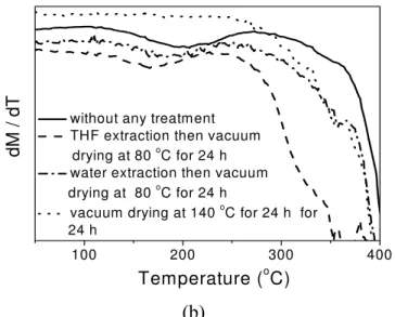
Figure 2.13 TGA traces of the polymerized product E5 subjected to: (1) no
treatment; (2) THF extraction and then vacuum drying at 80 °C for 24 h; (3) water extraction and then vacuum drying at 80 °C for 24 h and (4) vacuum drying at 140 °C for 24 h. (a) remaining mass percentage; (b) instantaneous loss in the mass percentage. ...30
Figure 2.14 TGA traces of the polymerized product E19 subjected to one of the
following treatments: (1) without any treatment; (2) water extraction then vacuum drying at 80 ºC for 24 h; (3) methanol extraction then vacuum
drying at 80 ºC for 24 h; (4) THF extraction then vacuum drying at 80 ºC for 24 h and (5) acetone extraction then vacuum drying at 80 ºC for 24 h. (a) accumulated mass loss; (b) instantaneous mass loss. ...32
Figure 2.15 Schematic of the N-trifluoroacetylation reaction of polyamides with
TFAA. ...34
Figure 2.16 FTIR spectrum of the residual liquid compounds of a mixture of
toluene/TFAA (8 ml/4 ml) after 30 min of rotary evaporation at 30 ºC. That of toluene is shown for comparison. ...36
Figure 2.17 FTIR spectrum of the residual liquid compounds of a mixture of
THF/TFAA (8 ml/4 ml) after 30 min of rotary evaporation at 30 ºC. Those of THF and TFAA alone are shown for comparison...37
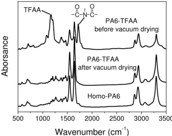
Figure 2.18 FTIR spectra of the homo-PA6 and the N-trifluoroacetylated
homo-PA6 (PA6-TFAA) before and after the vacuum drying at 80 °C for 2 h...38
Figure 2.19 FTIR spectra of the PS-g-PA6 and the N-trifluoroacetylated
PS-g-PA6 before and after the vacuum drying at 80 °C for 2 h...38
Figure 2.20 Mass fraction of the PS backbone and that of PA6 grafts and
PS-g-PA6 from E5 after 15 or 24 h of N-trifluoroacetylation reaction using chloroform as a co-solvent as a function of the molar mass of PS-g-PA6b. Experimental and calculation methods will be given in the subsequent sections...39
Figure 2.21 SEC traces of the homo-PA6 and PS-g-PA6 from E12 from the RI
detector after N-trifluoroacetylation reaction using chloroform as a co-solvent...40
Figure 2.22 UV spectra of the PS-co-TMI, PA6-TFAA, PS-g-PA6-TFAA
solutions in THF. The mass concentrations are 0.2, 0.05 and 0.04 mg/ml in the PS-co-TMI, homo-PA6 and PS-g-PA6, respectively...41
Figure 2.23 SEC traces of the N-trifluoroacetylated homo-PA6 and PS-g-PA6
from E12 from UV detection at 238 and 260 nm. ...42
Figure 2.24 SEC traces of the N-trifluoroacetylated PS-g-PA6 from E5 detected
by RI and UV-254 detectors. The N-trifluoroacetylation reaction was carried out with the use of THF as a co-solvent...43
Figure 2.25 SEC trace of the N-trifluoroacetylated PS-g-PA6 from E11
corresponding to the UV detection at 238 nm. The shaded area represents the integrated UV absorbance. ...44
Figure 2.26 Integrated areas of the SEC traces of the PS-co-TMI or the
N-trifluoroacetylated PA6 as a function of the polymer (PS-co-TMI or homo-PA6) concentration for the UV detection at two different wavelengths: 238 and 260 nm...44
Figure 2.27 Mass fractions of PS-g-PA6 from E11 and E12 (a), those of the PS
backbone and PA6 grafts (b) and PS backbone/PA6 grafts mass ratios (c) as a function of the molar masses of PS-g-PA6. ...47
Figure 2.28 FTIR spectra of PS-co-TMI1, PS-co-TMI2, PS-co-TMI4,
Figure 2.29 Schematic of the reaction of PS-co-TMI with MAMA. ...50 Figure 2.30 SEC traces of the PS-co-TMI-MAMA using a dual UV detector at
254 and 367 nm as a function of its molar mass...51
Figure 2.31 FTIR spectra of PS-co-TMI4, residue H and solute F. The latter two
are from the polymerized product of E5. ...52
Figure 2.32 FTIR spectra of PS-co-TMI4 (a), the insoluble product of
PS-co-TMI4 after extraction in methanol under reflux for 1 h (b) and the as-polymerized product from E5 without any extraction (c). ...53
Figure 2.33 FTIR spectra of the insoluble material from Ex.4 and Ex.5 by
methanol extraction and homo-PA6...55
Figure 2.34 DSC thermograms of the insoluble material in methanol from EX.4
and EX.5 by methanol extraction. They were heated from 50 to 250 ºC at 10 ºC/min and maintained at 250 ºC for 2 min to erase their previous thermal history, and then cooled to 50 ºC at 10 ºC/min (recrystallization), finally heated up again to 250 ºC at 10 ºC/min (melting). ...55
Figure 2.35 Mass percentages of the PS backbone and PA6 grafts of the four
pure PS-g-PA6 graft copolymers from E7, E11, E5 and E12 (a) and the mass ratios between the PS backbone and PA6 grafts (b) as a function of their molar masses...59
Figure 2.36 Melting and recrystallization DSC traces of PS-co-TMI4, PA6 and
three pure PS-g-PA6 graft copolymers from the experiments E11, E5 and E12. (a) Melting at 10 ºC/min, (b) Recrystallization at -10 ºC/min...60
Figure 2.37 Conversion of CL to PA6 as a function of time for experiments E14
and E5. ...61
Figure 2.38 Torque values and melting temperature as a function of time for
experiments E14 and E5. ...61
Figure 2.39 Effect of set temperature on the torque versus time of the
PS-co-TMI4/CL/Cat (50/50/5 by mass) polymerization system corresponding to E1 to E6...63
Figure 2.40 Effect of the NaCL/CL molar ratio on the polymerization rate
characterised by the torque of the PS-co-TMI4/CL/Cat (50/50/Cat by mass) polymerization system. The percentage of the Cat was 1.7, 5.0 and 8.4 wt.%, corresponding to E14, E5 and E16, respectively. ...63
Figure 2.41 Effect of the NaCL/CL molar ratio on the polymerization torques of
PS-co-TMI2/CL/Cat and PS-co-TMI4/CL/Cat (50/50/Cat by mass) polymerization systems with Cat being 1.7 and 5.0 wt.%, corresponding to E8, E13, E9 and E15. ...64
Figure 2.42 Effect of the NaCL/CL molar ratio on the mass percentages of the
PS backbone and PA6 grafts (a) and PS backbone/PA6 grafts mass ratios (b) of various PS-g-PA6 obtained from E14, E5 and E16 as a function of the respective molar masses of these pure graft copolymers. PS-co-TMI4/CL = 50/50 by mass. ...65
Figure 2.43 Effect of the TMI content in PS-co-TMI on the polymerization
with PS-co-TMI being PS-co-TMI1, PS-co-TMI2, PS-co-TMI4, PS-co-TMI6 and PS-co-TMI8, corresponding to E7, E8, E5, E9 and E10, respectively. ...66
Figure 2.44 Mass percentages of the PS backbone and PA6 grafts (a) and PS
backbone/PA6 grafts mass ratios (b) of various PS-g-PA6 from E7, E8, E5 and E10 as a function of the respective molar masses of these pure graft copolymers...67
Figure 2.45 Effect of the NCO/CL molar ratio on the torque evolution as a
function of time for the PS-g-TMI4/CL/Cat polymerization system corresponding to E12, E5 and E11, respectively. ...68
Figure 2.46 Effect of the NCO/CL molar ratio on the mass percentages of the PS
backbone and PA6 grafts (a) and PS backbone/PA6 grafts mass ratio (b) of various PS-g-PA6 obtained from E11, E5 and E12 as a function of the their molar masses...69
Figure 2.47 Comparison between the one-step and two-step feeding modes in
terms of the torque evolution as a function of mixing time for the polymerising system: (a) PS-co-TMI4/CL/Cat=50/50/1.7 (E14 one-step versus E17 two-step); (b) PS-co-TMI4/CL/Cat=50/50/5.0 (E5 one-step versus E18 two-step)...70
Figure 2.48 Mass percentages of the PS backbone and PA6 grafts (a) and PS
backbone/PA6 grafts mass ratios (b) of various PS-g-PA6 graft copolymers obtained from one-step (E5) and two-step (E18) feeding modes as a function of the respective molar masses. ...71
Figure 3.1 Mass percentage of the soluble residue after PS-g-PA6 dipped in
formic acid at 30 ºC as a function of dipping time. ...76
Figure 3.2 FTIR spectra of PS-co-TMI, Homo-PA6, PS-g-PA6 and the soluble
residue M after PS-g-PA6 dipped in formic acid at 30 °C for 12 h. ...77
Figure 3.3 PA6 contents in PS-g-PA6 copolymers by dipped in formic acid at 30
°C for different times (0, 3, 6, 12 and 24 h). The PA6 content obtained by two methods: (1) Weighting; (2) SEC...78
Figure 3.4 Mn (a) and Mw/Mn (b) of residue soluble in formic acid as a function
of time for the extraction in formic acid at 30 °C. ...79
Figure 3.5 Mass percentages of the PS backbone and PA6 grafts of the PS-g-PA6
graft copolymers after dipped in formic acid for different times at 30 ºC (a) and the PA6 grafts contents in PS-g-PA6 (b) as a function of their molar masses. ...80
Figure 3.6 Percentage of the soluble residue after PS-g-PA6 being dipped in
formic acid for 12 h as a function of temperature...81
Figure 3.7 PA6 graft chain content of PS-g-PA6 copolymers after being by
dipped in formic acid for 12 h at different temperature (30, 60 or 90 ºC). The PA6 graft chain content obtained by two methods: (1) Weighting; (2) SEC. ...81
Figure 3.8 Mn (a) and Mw/Mn (b) of residue soluble in formic acid as a function
Figure 3.9 Mass percentages of the PS backbone and PA6 grafts of the PS-g-PA6
graft copolymers after dipped in formic acid for 12 h at different temperature (30, 60 and 90 ºC) (a) and the PA6 grafts content in PS-g-PA6 (b) as a function of their molar masses. ...83
Figure 3.10 Torque and melting temperature versus time of PS-g-TMI/CL/Cat
(30/70/5) polymerisation system. Rotate speed of screw: 65 rpm, temperature: 230 ºC. ...84
Figure 3.11 Torque and melting temperature versus time of the CL/Cat/TDI
(100/6/3.6) polymerisation system. Rotate speed of screw: 65 rpm, temperature: 230 ºC. ...85
Figure 3.12 TEM micrographs of the phase morphology of various PS-g-PA6 by
different treatment. A: Pure PS-g-PA6; B: Formic acid treatment 12 h at 30 ºC; C: Static annealing for 2 h at 230 ºC;D: Formic acid treatment 12 h at 30 ºC after static annealing for 2 h at 230 ºC; E: Haake mixing for 10 min at 230 ºC; F: Formic acid treatment 12 at 30 ºC after Haake mixing for 10 min at 230 ºC...86
Figure 3.13 Percentage of soluble residue after PS-g-PA6 extracted in formic
acid for static annealing and Haake mixing for different time at 230 ºC...87
Figure 3.14 Mn of soluble residue after PS-g-PA6 extracted in formic acid for
static annealing and Haake mixing for different time at 230 ºC. ...87
Figure 3.15 PA6 graft chain contents of PS-g-PA6 copolymers that were treated
by static annealing and Haake mixing for different time at 230 ºC and then extracted in formic acid for 12 h at 30 ºC. The PA6 graft chain content obtained by two method: (1) Weight method; (2) SEC method. ...88
Figure 3.16 FTIR spectra of the soluble residue after PS-g-PA6 dipped in formic
acid for 12 h at 30 °C. Residue M, N and O came from the PS-g-PA6 without treatment, by static annealing for 2 h at 230 ºC and Haake mixing for 10 min at 230 ºC, respectively...89
Figure 3.17 Degradation mechanism of the PA6 graft in Haake mixing or static
annealing. ...90
Figure 3.18 Mass percentages of the PS backbone and PA6 grafts of the
PS-g-PA6 graft copolymers after dipped in formic acid for different time at 30 ºC (a) static annealing at 230 ºC for different time (0, 5, 10, 30, 60 and 120 min); (b) Haake mixing at 230 ºC for different time (0, 2, 5, 10 and 20 min) ...91
Figure 3.19 PA6 graft chain content in PS-g-PA6 graft copolymers after dipped
in formic acid for different time at 30 ºC. (a) static annealing at 230 ºC for different time (0, 5, 10, 30, 60 and 120 min); (b) Haake mixing at 230 ºC for different time (0, 2, 5, 10 and 20 min) ...92
Figure 4.1 Complex viscosity vs. frequency for the PS, PA6 and PS/PA6 blends
(80/20, 20/80) blend at 230 ºC. ...98
Figure 4.2 SEM micrographs of microtomed surface for the various PS/PA6
(20/80) blends: (A) without PS-g-PA6, (B) PS-g-PA6a (5%), (C) PS-g-PA6a (10%), (D) PS-g-PA6a (15%), (E) PS-g-PA6b (5%), (F) PS-g-PA6b (10%),
(G) PS-g-PA6b (15%), (H) PS-g-PA6c (5%), (I) PS-g-PA6c (10%), (J) PS-g-PA6c (15%), (K) PS-g-PA6d (5%), (L) PS-g-PA6d (10%) and (M) PS-g-PA6d (15%). The compatibilizer concentration was based on the dispersed phase concentration. Mixing temperature: 230 ºC; mixing time: 8 min and rotation speed: 65 rpm. ...100
Figure 4.3 Effect of PS-g-PA6 structure and composition as the compatibilizer
on emulsification curves of the PS/PA6 (20/80) blend. The PS-g-PA6 concentration bases on the mass of the dispersed phase. Mixing temperature: 230 ºC, mixing time: 8 min; rotation speed: 65 rpm. Symbols: experimental data; lines: trend line...101
Figure 4.4 SEM micrographs of microtomed surface for the various PS/PA6
(80/20) blends: (A) without PS-g-PA6, (B) PS-g-PA6a (5%), (C) PS-g-PA6a (10%), (D) PS-g-PA6a (15%), (E) PS-g-PA6b (5%), (F) PS-g-PA6b (10%), (G) PS-g-PA6b (15%), (H) PS-g-PA6c (5%), (I) PS-g-PA6c (10%), (J) PS-g-PA6c (15%), (K) PS-g-PA6d (5%), (L) PS-g-PA6d (10%) and (M) PS-g-PA6d (15%). The compatibilizer concentration was based on the dispersed phase concentration. Mixing temperature: 230 ºC; mixing time: 8 min and rotation speed: 65 rpm. ...102
Figure 4.5 Effect of PS-g-PA6 structure and composition as the compatibilizer
on emulsification curves of the PS/PA6 (80/20) blend. The PS-g-PA6 concentration bases on the mass of the dispersed phase. Mixing temperature: 230 ºC, mixing time: 8 min; rotation speed: 65 rpm. Symbols: experimental data; lines: trend line...103
Figure 4.6 Schematic diagrams of the morphology formation process for PS/PA6
(80/20) and (20/80) blend systems with PS-g-PA6 as the compatibilizer..106
Figure 5.1 Complex viscosity vs. frequency for the PS, PA6 and PS/PA6 blends
(50/50) at 230 ºC. ... 112
Figure 5.2 Effect of the quiescent annealing on the morphology of the PS/PA6
(50/50) blend obtained after mixing at 100 rpm at 230 ºC for 10 min. Without annealing (a); annealing at 230 ºC for 5 min (b), 10 min (c) and 15 min (d); annealing at 235 ºC for 5 min (e); 10 min (f) and 15 min (g); annealing at 240 ºC for 5 min (h), 10 min (i) and 15 min (j)... 114
Figure 5.3 Pore diameter (d) vs. annealing time for the PS/PA6 (50/50) blend at
different annealing temperatures (230, 235 and 240 ºC). ... 115
Figure 5.4 SEM micrographs of PS/PA6/PS-g-PA6 (50/50/1) blends after mixing
at 100 rpm for 10 min at 230 ºC followed by annealing at 240 ºC. The blend with PS-g-PA6e as the compatibilizer was annealed for 0 (a), 5 (b), 10 (c) and 20 min (d), respectively; the blend with PS-g-PA6f as the compatibilizer was annealed for 0 (e), 5 (f), 10 (g) and 20 min (h), respectively; the blend with PS-g-PA6g as the compatibilizer was annealed for 0 (i), 5 (j), 10 (k) and 20 min (l), respectively... 116
Figure 5.5 Effect of adding 1 wt.% of PS-g-PA6 graft copolymer on the
morphology of the PS/PA6 (60/40) blend after mixing at 100 rpm for 10 min at 230 ºC followed by annealing at 240 ºC. Without PS-g-PA6 and
annealing for 0 (a), 5 (b) and 15 min (c), respectively; with PS-g-PA6e and annealing for 0 (d), 5 (e) and 15 min (f), respectively; with PS-g-PA6f and annealing for 0 (g), 5 (h) and 15 min (i), respectively; with PS-g-PA6g and annealing for 0 (j), 5 (k) and 15 min (l), respectively; with PS-g-PA6h and annealing for 0 (m), 5 (n) and 15 min (o). ... 117
Figure 5.6 Pore diameters of the PS/PA6/PS-g-PA6 (60/40/1) blends versus
annealing time at 240 ºC. The compatibilizer was PS-g-PA6e, PS-g-PA6f, PS-g-PA6g and PS-g-PA6h, respectively. ... 118
Figure 5.7 Schematic of the molecular architectures and molar masses of the
four PS-g-PA6 graft copolymers used in this work. ... 118
Figure 6.1 Emulsification curves of the PS/PA6 (80/20) blend for four different
feeding modes. The PS-g-PA6f concentration was based on the mass of the dispersed phase. (a) rotation speed at 65 rpm, (b) rotation speed at 130 rpm. Mixing time: 8 min for the one-step feeding and 4 min for the two-step feeding after the last component of the blend was charged; temperature = 230 ºC. Symbols: experimental data; lines: trend lines. ...125
Figure 6.2 SEM micrographs of microtomed surface of the PS/PA6/PS-g-PA6f
(80/20/20.6) blend for four different feeding modes. (A) Feeding mode 1, (B) Feeding mode 2, (C) Feeding mode 3 and (D) Feeding mode 4. Mixing time: 8 min for the one-step feeding and 4 min for the two-step feeding after the last component of the blend was charged; temperature = 230 ºC. ...126
Figure 6.3 SEM micrographs of microtomed surface of the PS/PA6/PS-g-PA6f
(80/20/13.7) blend change with mixing time for feeding mode 1. Mixing temperature = 230ºC and rotation speed = 65 rpm. Mixing time: (A) 2 min, (B) 4 min, (C) 6 min, (D) 10 min...128
Figure 6.4 Change in the size of the dispersed phase of the PS/PA6/PS-g-PA6f
(80/20/13.7) blend with mixing time for different feeding modes. Mixing temperature = 230ºC and rotation speed = 65 rpm. For feeding mode 1 time “0” corresponds to the moment when all the components were fed to the mixer. In the other feeding modes it corresponds to the moment when the last component was fed to the mixer, i.e., 4 min after the first two components were fed to the mixer. Symbols: experimental data; lines: trend lines. ...128
Figure 7.1 Underlying chemistry used for the preparation of tracer-emulsifier133 Figure 7.2 Screw configurations of the twin screw extruder ...134 Figure 7.3 Infrared spectra of PS-co-TMI before and after reaction with MAMA.
...136
Figure 7.4 Linear relationships between the intensity of UV absorption of
MAMA and its concentration in THF at room temperature. The UV wavelength is located at 367 nm...136
Figure 7.5 Torque value as a function of time for the polymerization system of
PS-co-TMI-MAMA/CL/Cat: (a) 30/70/5; (b) 70/30/5. Temperature: 230 ºC; screw speed: 65 rpm...137
THF. The mass concentrations of polymers are 0.2 and 0.04 mg/ml (excluding the mass of TFAA in PA6-TFAA and PS-g-PA6-TFAA), respectively. ...137
Figure 7.7 Mass percentages of the PA6 grafts, PS backbone and MAMA of the
tracer-emulsifier A and tracer-emulsifier B as a function of their molar mass...139
Figure 7.8 A typical residence time distribution curve. Screw speed: 100 rpm;
Feed rate: 13 kg/h...140
Figure 7.9 Mass distribution of tracer-emulsifier corresponding to the RTD
curve in Figure 7.8. ...140
Figure 7.10 Comparison of the RTD and DSD curves obtained using two
different tracer-emulsifiers and PS-tracer (only RTD). Their masses are 4.8, 4.8 and 0.16 g, respectively. Feed rate: 13 kg/mol; Screw speed: 100 rpm. ...142
Figure 7.11 Effect of the mass of the tracer-emulsifier A for an experiment on
the RTD and DSD curves. Feed rate: 13 kg/h; screw speed: 100 rpm...143
Figure 7.12 Effect of the mass of the tracer-emulsifier B for an experiment on
the RTD curves. Feed rate: 13 kg/h; screw speed: 100 rpm. ...143
Figure 7.13 SEM micrographs of microtomed surface for PS/PA6 (80/20) blends
collected at different extruder die exit at different times. In the extrusion process, the tracer-emulsifier A was injected to the hopper as a pulse at zero time. The mass of tracer-emulsifier A for an experiment is 1.6 g (A), 3.2 g (B) and 4.8 (C). ...144
Figure 7.14 Comparison of DSD curves and mass distribution of
tracer-emulsifier of PS/PA6 (80/20) blend systems extruded in TSE with different amounts of tracer-emulsifier A for an experiment. The mass distribution of tracer-emulsifier obtained from the data in Figure 11. The mass indicated in the figures corresponds to the amounts of tracer-emulsifier A injected to the extruder...145
Figure 7.15 Effect of the screw speed on the RTD and DSD curves. The mass of
tracer-emulsifier A injected to the extruder is 3.2 g; feed rate is 13 kg/h. .146
Figure 7.16 Effect of the PS/PA6 ratio on RTD and DSD curves. PS/PA6 mass
ratio is 90/10 (a) and 80/20 (b); the mass of tracer-emulsifier A injected to the extruder is 1.6 g; feed rate is 13 kg/h; screw speed is 100 rpm. ...146
Figure 7.17 Effects of the amount of the tracer-emulsifier (a), the screw speed (b)
and the PS/PA6 mass ratio (c) on the emulsification curve of the PS/PA6 blend. The emulsification curve from a Haake torque rheometer (a batch mixer) is shown in c. The structure of the emulsifier used is similar to that of the tracer-emulsifier. The PA6 content and the number of the PA6 grafts per PS backbone of the emulsifier were 30.3% and 6.6, respectively. ...149
List of Tables
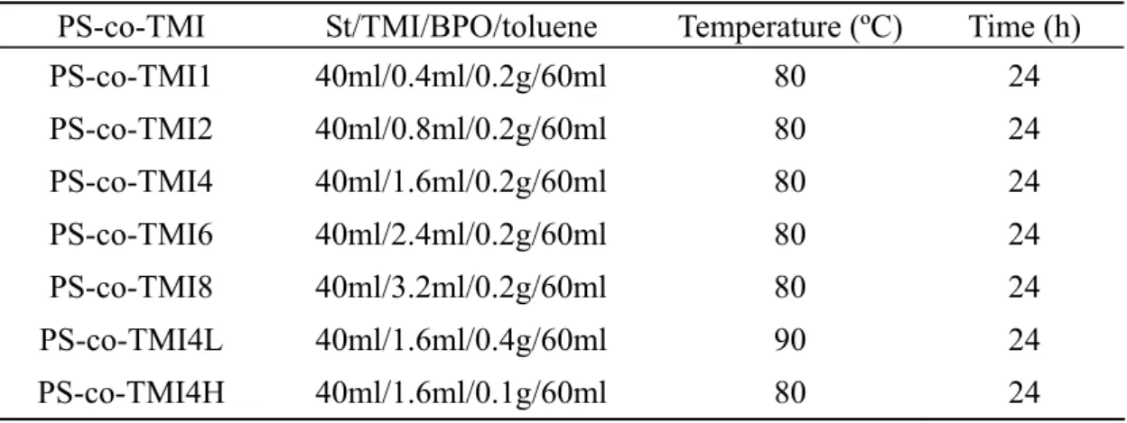
Table 2.1 Compositions of St, TMI, BPO and toluene, polymerization
temperature and time used for the synthesis of PS-co-TMI. ...14
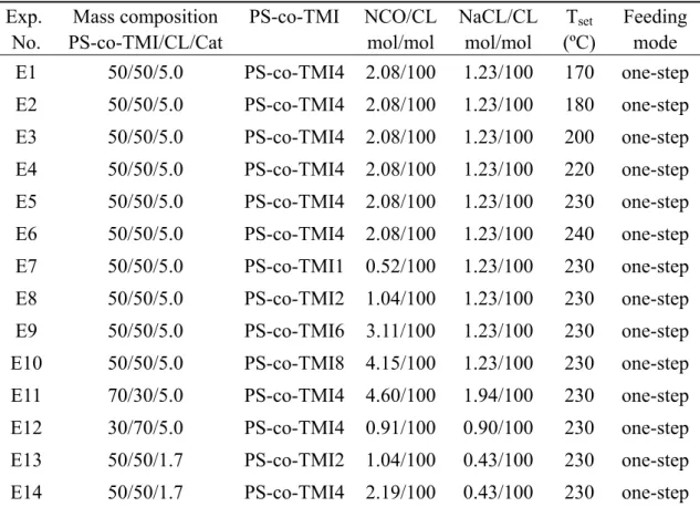
Table 2.2 Selected information on the experimental trials carried out in this work ...15
Table 2.3 Mass losses of various polymerized products subjected to different pre-drying times in a vacuum oven at 50 ºC...22
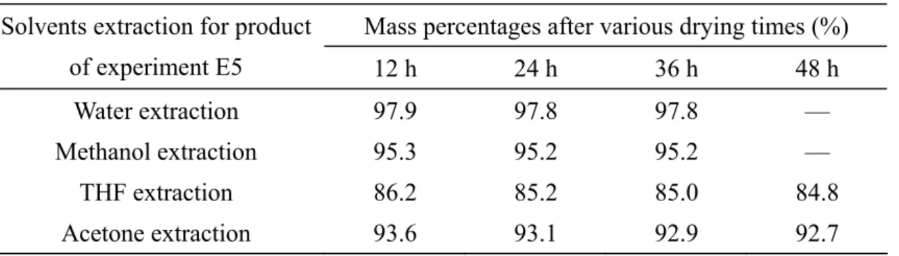
Table 2.4 Comparison of the CL conversions measured by extraction in various solvents. ...23
Table 2.5 Times necessary for complete solvent removal under vacuum drying at 80 °C. ...27
Table 2.6 CL conversions measured by vacuum drying at 140 ºC for 24 h ...27
Table 2.7 CL conversions obtained by the nitrogen analysis ...30
Table 2.8 CL conversions measured by extraction in various solvents...31
Table 2.9 CL conversions of E19 obtained by vacuum drying at 140 ºC and TGA ...32
Table 2.10 Molar masses of N-trifluoroacetylated homo-PA6 and PS-g-PA6 from E12 by SEC using a RI detector and based on the PS standards. ...40
Table 2.11 Molar masses of the N-trifluoroacetylated homo-PA6 and PS-g-PA6 from E12 calculated from the UV detection at 238 and 260 nm and based on the PS standards. ...42
Table 2.12 Mass fractions of the PS backbone and PA6 grafts of PS-g-PA6 graft copolymers obtained by SEC and selective extraction. ...45
Table 2.13 The molar mass and TMI content of as-synthesized PS-co-TMI...49
Table 2.14 Mass percentages of the various fractions of four as-polymerized products obtained according to the procedure in Figure 2.5...52
Table 2.15 Selected information on the experimental trials for CL/Cat mixing and the CL conversion ...54
Table 2.16 Mass percentages and the molar masses of the PS backbone and a single PA6 graft of four pure PS-g-PA6 graft copolymers obtained by successive extraction...57
Table 2.17 Composition and relative molar mass of pure PS-g-PA6 obtained by SEC. ...57
Table 2.18 Heating behavior of the PA6 grafts of three PS-g-PA6 graft copolymers and homo-PA6 ...60
Table 4.1 Literature results on the emulsification efficiency of copolymers. ...94
Table 4.2 Normalized interfacial coverage (Σ/Σmax) for PS/PA6/PS-g-PA6 blends. ...104
Table 4.3 Asymmetry index obtained from the PS/PA6 blends without and with PS-g-PA6...107
Table 5.1 Literature results on the efficiency of copolymers to stabilize co-continuous morphology... 110
(Σ /Σmax) for PS/PA6/PS-g-PA6 (60/40/1) blends before and after the
annealing at 240 ºC. ... 119
Table 6.1 Literature results on the effects of feeding mode on the morphology of
reactive blends. ...122
Table 6.2 Description of four feeding modes for the PS/PA6/PS-g-PA6f blends.
...124
Table 7.1 Molar mass, the PA6 content and the MAMA content of two
Chapter 1
Introduction
1.1
Motivation and objectives
Polymeric alloys or polymer blends hold considerable research interest. Just as metal alloys have long been used because they have properties unattainable in any one metal alone, blending existing polymers can also used as a means of creating new materials with combination of properties superior to the components at relatively low cost. However, the actual fabrication of polymer blends poses significant challenges. Most polymer pairs are immiscible and thermodynamically unstable, which leads to the phase separation into macroscopic domain and may yield a material with poor properties. To address this challenge, immiscible polymer blends must be compatibilized. A common method of compatibilization is the introduction of another component known as a compatibilizer (also called interfacial modifier or emulsifier), which is made up of segments that are chemically identical to or have affinity with each of the polymer components. Thus the compatibilizer molecule can be convenient to locate between the two polymer phases, which results in promotion of the interfacial adhesion, reduction of interfacial surface tension, promote the dispersion of one phase in another and stabilize resulting blends [ - ]1 3. Therefore, it is very important to find an additive that act as an effective compatibilizer.
Block or graft copolymers are commonly used as compatibilizers in immiscible polymer blends. The efficiencies of block or graft copolymers as compatibilizers are believed to depend on their molecular architectures [ -4 10], molecular weights [11 15]- , compositions [15 18]- , the interaction parameter balance between the homopolymers and the copolymer blocks [19 22]- . Therefore, there are, at least, four important factors to be kept in mind when selecting a block copolymer for a specific application: choice of monomers, molecular architecture, composition, and molecular weight. Choice of monomers controls the enthalpy of the system, while the molecular architecture, composition and molecular weight control their aggregation and processing characteristics. The former is determined by the blend systems and the copolymer is composed of the same or similar monomers that are used in the polymers making up the blends. Therefore, the choice of copolymer focuses mainly on the latter.
In order to choose the suitable compatiblizer for an immiscible polymer blend, we first have to know how copolymer architecture and composition affect the compatibilization of a polymer blend. Most of the experimental reports in this field
are related to the effect of the molecular architecture of the block copolymers on the compatibilization of immiscible polymer blends. This is because their molecular parameters are easy to control using anionic polymerization process. More importantly, there are a few commercially available block copolymers (mainly those based on styrene-butadiene or –isoprene block copolymers) that can be used as compatiblizers.
However, many important polymer blends are constituted by components, whose corresponding block copolymers are difficult to prepare. In addition, the prevailing method of in-situ compatibilization results mainly from the formation of graft copolymer by the coupling reaction between two functional polymers [23 24, ]. Currently, there are very few studies about how changes in the graft copolymer architecture such as graft chain length and density will impact its ability to compatibilize an interface. The objective of the work presented in this thesis is to develop a novel method to synthesize the graft copolymers with controllable architecture and to investigate the compatibilized efficiency of the resulting graft copolymers with different molecular architectures and/or molecular weights.
1.2
Overview of thesis
An important challenge in the study of compatibilizing efficiency of graft copolymer in polymer blends lies in the development of controllable synthesis of the graft copolymer. The first part of this thesis focuses on addressing this challenge. The second part of this thesis is to investigate the compatibilizing efficiency of the synthesized graft copolymers as compatibilizers. A brief overview of the organization of this thesis is as follows.
In chapter 2, a novel method for the controllable synthesis of graft copolymer was developed. The grafting of polyamide 6 (PA6) onto polystyrene (PS) is achieved by the use of a copolymer of styrene (St) and 3-isopropenyl-α,α-dimethylbenzene isocyanate (TMI), PS-co-TMI, to activate the polymerization of ε-caprolactam (CL) in the presence of sodium ε-caprolactam (NaCL) as an anionic catalyst. The control and analysis method of the structure of graft copolymer is addressed in detail.
Chapter 3 deals with the study of the degradation of the graft copolymer (PS-g-PA6) with PS as backbone and PA6 grafts in the formic acid extraction and at the high temperature and high shear. The latter was investigated at 230 ºC by two methods: one is annealing treatment, static press at a pressure of 10 MPa; the other is haake mixing, mix in haake torque rheometer.
Chapter 4 studies the compatibilizing efficiencies of the four as-synthesized graft copolymers in PS/PA6 blend systems with dispersed phase/matrix structure. The PS/PA6 composition is either 20/80 or 80/20. The role of the length and density of graft chains in compatibilizing PS/PA6 blend is discussed.
Chapter 5 evaluates the efficiency of the as-synthesized graft copolymers in stabilizing the morphology of PS/PA6 co-continuous phase in the process of quiescent annealing.
Chapter 6 investigates the effect of feeding mode on the morphology development of PS/PA6 (80/20) blend with PS-g-PA6 as compatiblizer.
Chapter 7 reports on a concept of tracer-emulsifier and its applications in continous polymer blending processes.
Finally, the mainly conclusion of this thesis are summarized and futher research directions are proposed in Chapter 8.
Chapter 2
A novel reactive extrusion process for the synthesis of
PS-g-PA6 graft copolymers
2.1
Introduction
2.1.1Synthesis methods of graft copolymer
A graft copolymer is composed of a polymer backbone to which one or more graft chains are connected through covalent bonds. Graft copolymers represent a valuable class of polymeric materials due to the availability of many structural variables which in turn can reveal a broad range of new materials with new properties
[25 27- ]
. These structural variables include: main and side chain polymer type; degree of polymerization and polydispersities of main and side chain; graft density (average spacing in-between the side chains) and so on.
Therefore, it is important to develop an easy and effective method to synthesize controlled graft copolymers with a view to obtain impact-resistant plastics by combining a hard polymer backbone with soft polymer graft chains, thermoplastic elastomers by grafting a hard polymer segments onto a soft polymer backbone, or amphiphilic copolymer used as the additive, dispersant and compatibilizer in polymer blend, etc [27 30]- .Generally, useful synthetic approaches to the preparation of graft copolymers include[25 27, ]: (I) “grafting through”, which is the homo-polymerization of a macromonomer or the copolymerization of a macromonomer with a monomer, (II) “grafting onto”, where the grafting of side chains onto a backbone is carried out via a coupling reaction between the pendant functional groups of the backbone and the end-functional group of grafts; and (III) “grafting from”, in this case the graft chains are grown from a polymer with multiple initiating sites located throughout its main chain. The above three strategies for the synthesis of graft copolymers are shown in Figure 2.1. In addition, noncovalent interactions, such as hydrogen bonding [31], ionic interaction [32], and so on, have also been used to graft surfactants onto linear polymer chains to form polymer graft architectures.
R
+
x x x or Y Y * * *+
monomer (a) (b) (c) macromonomer Gr afting thr ough Grafting onto Gra fting from YFigure 2.1 Scheme of three methods for the synthesis of graft copolymers: (a) “grafting through”, (b) “grafting onto” (X and Y are the pendant functional groups of the backbone and the end-functional groups of grafts, respectively), (c) “grafting from” (* is an initiating group).
2.1.1.1Grafting through
The “graft through” approach has been applied for the synthesis of graft copolymer for about twenty years. The approach is via random or systematic chemical attachment of initiating groups onto the molecular substrate, which in turn can enable the synthesis of branches. An example is the introduction of terminal vinylic group (double bond) in a macromonomer, which in turn can be polymerized by the radical polymerization [33 36]- .
For the preparation of the controlled structural graft copolymer, a living or controlled polymerization should be involved [28 37, ]. In general, the macromonomers can be synthesized by a living or controlled polymerization technique and thus be well defined the graft chain parameter [36 38, ]; the backbone parameters of graft copolymer also can be controlled by a living or controlled copolymerization of the macromonomers with a low molecular weight comonomer [39 40, ]. For example, Rieger and Dubois et al. [39] obtained the biodegradable and biocompatible poy(ε-caprolactone)-graft-poly(ethylene oxide) copolymers, by ring-opening copolymerization of ε-caprolactone and poly(ethylene oxide) (PEO) macromonomer, i.e., PEO end-capped by an ε-caprolactone unit. The control is effective on the composition and length of both the hydrophobic polyester backbone and the hydrophilic PEO grafts. However, the “grafting through” method still has been
deficient in controlling the spacing distribution of the graft chains because the reactivity ratios of macromonomer and comonomer influence the spacing distribution of the graft chains, which were influenced by many factors, such as the diffusion differences of macromonomer in comparison to the low molecular weight comonomer, the inherent reactivity of macromonomer and comonomer and the potential incompatibility of the propagating comonomer chain and the macromonomer [28 41, ].
2.1.1.2Grafting onto
In the “graft onto” method, the graft architecture is formed via a coupling reaction between the pendant functional groups (X) of the backbone and the end-functional group (Y) of grafts (see Figure 2.1b). This method provides the advantage that both the backbone and graft chain can be characterized separately, that is, the backbone and graft chain can be prepared via different living polymerization techniques independently so that the resulting graft copolymer is defined with respect to their backbone and grafts [25 27, ]. A characteristic example is the functionalization of polybutadiene with chlorosilane groups, via the hydrosilylation reaction, followed by the coupling reaction with living polystyrene chains [42].
You and Hong et. al. [41] report a novel “graft onto” procedure to prepare graft copolymers with controlled backbone length, grafting sites and grafting density: firstly, reversible addition-fragmentation transfer (RAFT) polymerization of styrene (St) was performed by using polytrithiocarbonate as chain transfer agent to produce trithiocarbonate-containing polystyrene (PS) with controlled distance between sequentially spaced trithiocarbonate functional group; Secondly, “graft points” maleic anhydride (MAH) were inserted into the backbone chain between St and trithiocarbonate; finally, Poly(ethylene glycol methylether) (PEGM) or poly(tetrahydrofuran) (PTHF) chains were linked onto the main chain by esterification reaction of maleic anhydride with PEGM or PTHF to from graft copolymer with well-controlled backbone length, graft sites and graft density.
However, the grafting density of graft copolymer synthesized with the “grafting onto” method is often limited for both kinetic and thermodynamic reasons [29]. First, with increasing grafting density, the diffusion of unreacted grafts to the reactive sites on the backbone slows down because of increasing steric hindrance. Second, the attachment of grafts to the backbone with a high grafting density becomes entropically unfavorable because the graft must change from a random coil conformation to a more stretched conformation once it is attached to the backbone. Thus, it is difficult to achieve the complete coupling reaction, which results in low
grafting efficiency and fail in controlling the graft sites and graft density. In addition, an incomplete coupling reaction often produces impure products and cause difficulty in purification.
2.1.1.3Grafting from
The “grafting from” method, is based on the growth of side chains from the active sites contained in the main polymer chain, has received much attention recently as a new path way for the preparation of well defined graft copolymer [25 27, ]. This technique procedure requires the generation of active sites on the main polymer chain, macroinitiator, which are capable of initiating the graft polymerization of an appropriately chosen monomer.
The “grafting from” method is most effective to control the structure of graft copolymers by living or controlled polymerization techniques. Generally, these well-defined macroinitiators can be obtained directly via various living or controlled polymerization techniques (atom transfer radical polymerization (ATRP) [43], anionic polymerization [44] and RAFT [45]), which allow the control of the main chain parameters as well as the sites and distribution of active that can determine the graft sites and the graft density. The grow of the graft chains by the active groups well-distributed along main chain initiating the polymerization of chosen monomer also can be well controlled by living or controlled polymerization techniques (ATRP
[29 30 46 50], ,
and anionic polymerization [51 52, ]). Therefore, the graft copolymer with high graft density and well-defined backbones and graft chains can be prepared. In particular, the purification of the resulting copolymer is much simper in comparison with the other two methods.
2.1.2Graft copolymer formation by reactive blending
The process of blending existing polymers holds considerable promise as a means of creating new materials with combination of properties superior to the components at relatively low cost. However, since most polymer pairs are immiscible, polymer blends often need to be compatibilized using block or graft copolymers [ ]1. The one that has been frequently practiced is the so-called in-situ (or reactive) compatibilization. In the in-situ compatibilization process, the graft copolymer can be formed directly by two techniques: one is the interfacial coupling reactions between two premade polymers bearing functional groups [53- 61], which is the most important application of the “grafting onto” method; the other is the in-situ polymerization of the chosen monomer from the macroinitiator [62 65- ], which is a typical application of the “graft from” method.
2.1.2.1Interfacial coupling reactions
Generally, interfacial coupling reactions require two functional polymers: one polymer is synthesized via a stepwise mechanism, which leaves functional groups at the chain ends such as polyamides, polyesters and polycarbonates; the other polymer has a few functional groups placed randomly along the chain, either by copolymerization (for example: the copolymer SMA of styrene (St) and maleic anhydride (MAH)) or by grafting onto the premade polymer (for example: the MAH grafting polyolefin) [61]. Thus the graft copolymers are formed by coupling reaction between the functional groups. Copolymer formation must occur during reactive extrusion process whose mean residence time is typically short and less than a few minutes. Therefore, coupling reaction should be fast to form anamount of copolymers sufficient to cover the phase interface and compatibilize a blend and/or to increase adhesion within the processing time. The most common reactive pair is amine/anhydride which has been used for most commercial reactively compatibilized blends, for example, polyamide/SMA [59] and amine terminal polystyrene (PS-NH2)
and anhydride terminal poly (methyl methacrylate) (PMMA-An). Many other reactive pairs such as carboxylic acid/epoxy [66] and hydroxyl and carbonyl [31] have been considered as a reactive pair for reactive compatibilization.
It is difficult to determine reactivity between two functional polymer chains. The concentration of functional groups is very low, so standard techniques like nuclear magnetic resonance (NMR) and fourier transform infrared spectroscopy (FTIR) do not have sufficient sensitivity [67]. Most blends have been developed based on property improvement and changes in morphology. It is inferred that coupling must be occurring if the morphology becomes finer and more stable. Some previous researchers have used solvent extraction to determine the amount of copolymer formed during processing by measuring the mass directly or aided by NMR or FTIR analysis [68 70]- . The blend is broken into a fine powder, then extracted first with a solvent for the matrix and then with one for the dispersed phase. By repeating this extraction sequence several times the mass of reactively formed graft copolymer can be estimated. However, this method can yield falsely high values due to the difficulty in complete removal of unreacted polymer.
If a mutual solvent can be found for both polymers, reaction conversion to copolymer can be measured with size exclusion chromatography (SEC) by using narrow distribution end functional polymers [67]. The sensitivity of the technique can be increased by 100-fold by incorporation of a fluorescent group on a polymer [71 72, ].
For example, Jeon and Feist et al. [59] used fluorescent pyrene to label SMA allowed the detection of small amounts of reactively formed block (SMA-g-PA66) in the PS/PA66/SMA blends via SEC with a fluorescence detector and found an extremely fast reactions giving > 60% conversion in 0.5 min mixing.
This approach is technically very attractive and economically appealing for preparing immiscible blends. However, it does not allow obtaining pure graft copolymers when the functional polymers are immiscible, unless the molar mass of at least one of the reactive polymer components is smaller than its critical entanglement molar mass, or once formed at the interfaces the copolymer chains walk away. Limited amounts of copolymer formed by interfacial reactions can be explained as follows [73 74, ]. First, the interfacial volume available for reaction between two immiscible polymers is often very small, even under intense mixing; second, the intrinsic reactivity of two mutually reactive groups attached to polymer backbones can be much smaller than their small-molecule analogues because of steric hindrance effects.
2.1.2.2In-situ polymerization
Hu et al. [62 64- ] have developed a novel reactive extrusion process to obtain compatilibilzed A/B immiscible polymer blends. It consisted of polymerizing a monomer of polymer B in the presence of polymer A. A fraction of polymer A chains bore initiating sites either at the chain end(s) or along the chain backbones, from which polymer B chains could grow, which is an application of “grafting from” method in bulk copolymerization. In the process, polymer B and a graft or block copolymer of A and B were formed simultaneously leading to in situ polymerized and in situ compatibilized A/B polymer blends. In fact, four phenomena are involved in the process: polymerization of MB which produces polymer B and causes phase separation and eventually phase inversion; formation of an A-B copolymer that stabilizes the system. For this reason, the method is called in situ polymerization and in situ compatibilization of polymer blends. Schematic description of this process is shown in Figure 2.2.
.
.
.
.
.
.
.
.
.
.
...
.
.
A+A*+MB.
.
.
.
.
.
. .
.
.
.
.
.
.
..
.
.
.
.
. .
.
.
.
.
. .
.
Ccc A/A-B/B Polymerization + phase seperation Copolymer formation + in situ compatibilizationFigure 2.2 Schematic description of the in-situ polymerization and in-situ compatibilization. A* denotes polymer A chains bore initiating sites either at the chain end(s) or along the chain backbones.
The above chemical process can be explored for two interesting applications. One is to obtain polymer blends with a variety of morphology including nanodisperspersion of one polymer in the other upon controlling the kinetics of polymerization, phase separation and copolymer formation. For example, nanoblends were obtained by polymerizing lactam like CL in the presence of polypropylene (PP) homopolymer and 3- isopropenyl-α,α-dimethylbenzene isocyanate (TMI) grafted PP (PP-g-TMI) [62 64- ], PP homopolymer and maleic anhydride (MAH) grafted PP (PP-g-MAH) [65] and poly(2,6-dimethyl-1,4-phenylene oxide) (PPO) and 4-methoxyphenylacrylate (MPAA) grafted PPO [75]. The other is to polymerize a chosen monomer onto a polymer backbone via initiating sites by reactive extrusion. The grafting polymerization route is expected to generate graft copolymers with very high purity. This is because, unlike interfacial coupling reactions, both the interfacial area limitation and steric hindrance effects are much reduced or totally absent.
Lactams such as CL is suitable as the monomer of the above graft polymerization because it can be polymerized anionically in the prescence of a catalyst like NaCL. Some 35 years ago, Matzner et al. [76] used the acrylic esters incorporated PS or PE as activators from which the polymerization of CL could grow in the presence of an anionic catalyst such as NaCL, leading to the formation of PA6 grafts. Ester and
bischloroformate bearing polymers were also used to activate the polymerization of CL to form graft copolymers [77 78, ]. However, the overall polymerization rate is often very slow because of the slow initiation rate and is thus incompatible with reactive extrusion process. The latter have residence times typically less than 5 min. An activator is thus required to accelerate the initiation rate and consequently the polymerization rate. Hu et al. [73 74 79, , ] used an isocyanate-bearing polypropylene (PP-g-TMI) as an activator and obtained high purity graft copolymers of PP and PA6 in about a minute in a batch mixer. TMI not only shows much higher activation performance and but also sufficiently stable under extrusion conditions (high temperatures and exposure to moisture).
Hu et al. [74] had studied on the effects of temperature and the concentrations of NaCL and the isocyanate group in the form of PP-g-TMI on the polymerization rate. The torque as a function of time could be used as rapid and convenient measures for evaluating and controlling the effects of chemical and operating conditions on the polymerization rate [79]. For example, a high polymerization rate will necessarily lead to a fast increase in the viscosity of the polymerization system and consequently a rapid increase in the polymerization temperature and torque, and vice versa. Results suggested that if the polymerization is to be carried out by a reactive extrusion process whose mean residence time is less than a few minutes, it is recommended that the polymerization temperature be higher than 220 ºC. Moreover, the molar ratio between NaCL and CL should be higher than 0.5 and at the same time that between the isocyanate group in the form of PP-g-TMI and NaCL, should be smaller than 4.
2.2
Study object and strategy
The previous studies of Hu et al. have obtained pure graft copolymer PP-g-PA6 by the anionic polymerization of CL from PP-g-TMI. However, they did not answer the following two important questions. First, did all the isocyanate moieties in the PP-g-TMI participate in the activation of the polymerization of CL? If yes, the number of the PA6 grafts per PP chain was then equal to that of the isocyanate moieties per PP-g-TMI chain. Second, the anionic polymerization scheme of CL is known to be complex [80 81, ]. For the PP-g-TMI/CL/NaCL graft polymerization system, what were the composition of the resulting polymer product and the structure of the resulting graft copolymer? This work is aimed at addressing those two questions upon using a random copolymer of styrene (St) and TMI (PS-co-TMI) as the activator. The resulting copolymer is expected to be a graft copolymer with the PS as backbone and