HAL Id: hal-02281367
https://hal.archives-ouvertes.fr/hal-02281367
Submitted on 9 Sep 2019HAL is a multi-disciplinary open access archive for the deposit and dissemination of sci-entific research documents, whether they are pub-lished or not. The documents may come from teaching and research institutions in France or abroad, or from public or private research centers.
L’archive ouverte pluridisciplinaire HAL, est destinée au dépôt et à la diffusion de documents scientifiques de niveau recherche, publiés ou non, émanant des établissements d’enseignement et de recherche français ou étrangers, des laboratoires publics ou privés.
In situ fine-tuning of microfluidic chips by swelling and
its application to droplet microfluidics
Juan González-estefan, Mathieu Gonidec, Thi Thiet Vu, Nathalie Daro,
Guillaume Chastanet
To cite this version:
Juan González-estefan, Mathieu Gonidec, Thi Thiet Vu, Nathalie Daro, Guillaume Chastanet. In situ fine-tuning of microfluidic chips by swelling and its application to droplet microfluidics. Advanced Materials Technologies, Wiley, 2019, 4 (8), 1900232 (9 p.). �10.1002/admt.201900232�. �hal-02281367�
1
In situ fine-tuning of microfluidic chips by swelling and its application to droplet microfluidics
Juan H. González-Estefan, Mathieu Gonidec,* Thi Thiet Vu, Nathalie Daro, and Guillaume Chastanet
J. H. González-Estefan, Dr. M. Gonidec, T. T. Vu, Dr. N. Daro, and Dr. G. Chastanet CNRS, ICMCB, UMR 5026, F-33600 Pessac, France
J. H. González-Estefan, Dr. M. Gonidec, T. T. Vu, Dr. N. Daro, and Dr. G. Chastanet Univ. Bordeaux, ICMCB, UMR 5026, F-33600 Pessac, France
E-mail: mathieu.gonidec@icmcb.cnrs.fr
Keywords: microfluidics, PDMS, swelling, droplets
Abstract
Over the last two decades, polydimethylsiloxane (PDMS) has been widely used as the material of choice for fast-throughput prototyping of microfluidic devices due to the ease of fabrication of PDMS devices by soft-lithography replica molding methods. Nevertheless, PDMS is known to swell significantly in a variety of organic solvents which has sometimes limited its use in synthetic chemistry and has led the microfluidic community to consider PDMS as being “incompatible” with such solvents. Nevertheless, as shown here, when analyzed deeper and controlled properly, the solvent-induced swelling of PDMS actually constitutes a potentially useful phenomenon that can become a simple tool to control and adjust finely and dynamically the geometry of microfluidic chips in situ. In this paper, this method is applied to the control of the behavior of a variety of droplet generators. The simplicity and efficiency of this approach make it a great asset for droplet microfluidics synthesis, for which micro-reactor sizes are a critical parameter that is often overlooked due to its complex implementation. In a more general sense, it is expected that integrating swelling into design should allow to adjust the function of many different types of chips exhibiting geometry-driven functions.
2
1. Introduction
The precise control and manipulation of fluids enabled by microfluidics has greatly attracted the attention of the scientific community.[1] In particular, droplet microfluidics—the
generation and manipulation of droplets in micro-channels—has been used for a myriad of applications, including the synthesis of metal-organic frameworks[2,3] and CdS
nanoparticles,[4] the crystallization of proteins,[5] and drug delivery[6] among others. The size of the droplets generated in those devices is of critical importance for such practical
applications. For protein crystallization, for instance, the nucleation rate is proportional to the droplet volume (homogenous nucleation), or to its surface area (heterogeneous nucleation).[5] These effects likely influence the synthesis of micro- and nanocrystals of a variety of
materials,[7,8] but few detailed studies assess the influence of droplet sizes due to the complications involved in controlling it finely and in obtaining small droplets.
There is thus a growing interest in producing well-characterized droplets with a specific, stable, and narrow size distribution. Many studies have been devoted to the
prediction of droplet sizes,[9–12] and the fundamental aspects are reasonably well understood, at least when considering mesoscale systems with droplets sizes above a few micrometers in diameter. The diameter of droplets generated by a microfluidic junction is essentially
proportional to the inverse of the capillary number of the continuous phase.[13] Based on this rationalization, a few experimental strategies are available to produce streams of droplets with a given target diameter. A simple approach consists in using a given chip geometry and changing its operating conditions, by adjusting some process parameter such as the flow rates (that control the velocity of the fluids),[10,14] the interfacial tension (by adding surfactants),[15] the nature and viscosity of the fluids[13] or the temperature of the system[14] (that in turn affects the latter two parameters). These approaches, together with active droplet break-up methods (like those based on the manipulation of electric fields,[16,17] mechanical forces[18–20] or channel deformations[21,22]) build the commonly used set of tools for the control of droplet
3
sizes in microfluidic devices. Each of them presents unique advantages and drawbacks. Those include complications due to a long iterative design and manufacture process to adjust the behavior of the chips, the use of additional costly, specialized equipment (such as voltage sources, or piezoelectric ultrasound generators),[16–20] the design of either specific, complex chips (incorporating micro-patterned electrodes for instance) or multi-layer chips (requiring the use of mask aligners),[21,22] or changes in some fundamental parameters (flow rate, temperature…) that would have a significant impact on the reaction conditions for materials synthesis. Indeed when using droplets as confined micro-reactors, changing the flow rates of the dispersed and the continuous phases leads to changes in the residence time inside the chip (which affects the reaction conditions[23] and the material production rate) while changing the temperature of the system will strongly alter the reaction kinetics. To avoid these issues, and to keep the operating conditions constant, the only adjustable parameter left is that of the geometry of the chip (that affects the flow velocity and the capillary number). The droplet sizes can thus be adjusted easily and empirically, by modifying the critical dimensions of the droplet generator (T-junction, flow-focusing junction…) iteratively, until the desired droplet size is achieved. Unfortunately, this approach is highly unpractical, as it requires the
manufacture of a new chip at each iteration. Even then, minor fabrication defects and
inconsistencies in the reproducibility of the fabrication method could alter the geometry of the chip, and the achieved nominal droplet diameter could ultimately deviate from the desired one.
Taking into account all of the above, and with the idea that droplet microfluidics is a fantastic tool for chemistry and for materials synthesis in general,[24] we designed an easy method to adjust the size of droplets generated in microfluidic chips without resorting to the use of surfactants, without changing the flow rates or the temperature of the system, without requiring very precise microfabrication methods, and without the need for complicated and costly setups. As we will show, this can be done by adjusting the geometry of a poly(dimethyl
4
siloxane) (PDMS) chip in situ, via a controlled deformation induced by swelling in the presence of some solvent.
2. Results and Discussion
Swelling is a well-known phenomenon that has been studied for decades, but despite a few recent studies about the kinetics of swelling of PDMS when exposed to organic solvents[25] and the effect it has on the deformation of microchannels,[26] the literature about potential applications of this phenomenon is still scarce. Indeed, it is still mainly considered as an issue to be avoided, and solvents that cause PDMS to swell are often described as being
“incompatible with PDMS”.[27,28] Despite this negative preconception, we show here that the channel deformations induced by swelling can be controlled precisely, reversibly and at will, by a simple adjustment of the concentration of a swelling solvent in the hydrophobic phase. This simple, tunable and reversible methodology provides a good, empirical control of the sizes of droplets generated by standard T-junctions and flow-focusing junctions, achieving (in swollen chips) a reduction of the droplet volume by up to two orders of magnitude.
2.1. Experimental design
To probe experimentally the effect of swelling on microfluidic chips, we sought to establish if the deformations of micro-channels could be controlled by tuning the nature and composition of the fluids flowing through them, and in particular, by diluting a solvent known to cause significant swelling into one that is known to be inert towards PDMS. We first studied the effect of swelling on the deformation of PDMS micro-channels of various dimensions in single-phase flow conditions with a model chip, we then applied our findings to the control of a simple T-junction droplet generator and finally applied it to adjusting the operation
conditions of microfluidic chips designed for reactive mixing. For all of our experiments, we used mixtures of mineral oil and toluene (we obtained qualitatively similar results for other
5
solvents presenting a strong swelling capability such as petroleum ether or xylenes) as a continuous, hydrophobic phase, and water (or aqueous solutions) as the dispersed phase.
2.2. Controlled deformations of PDMS micro-channels
Intuitively, the swelling-induced deformations of PDMS micro-channels should depend on the concentration of the solvent inducing swelling in the fluid mixture flowing through it.
Additionally, it should also depend on the geometry of the microstructures themselves. For example, a 10-μm wide PDMS structure sandwiched between two micro-channels is essentially a PDMS membrane, and can be expected to swell differently than the two opposing walls of a single isolated microchannel (separated from other flow structures by a few millimeters or centimeters), that can be considered as semi-infinite walls. Since
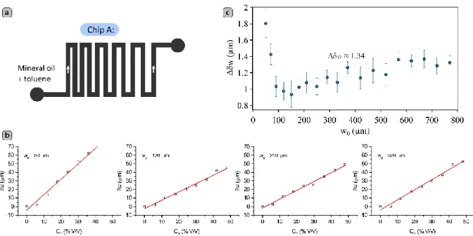
functional chips usually consist of micro-channels separated by microstructures of different critical widths, understanding the behavior of microfluidic chips subject to swelling requires studying such size-dependent properties. Chip A (see Figure 1a) was designed for this purpose and consists of a 500 µm wide (and 75 µm high) zigzagged channel in which the separation of the channels vary gradually, ranging from 30 to 770 µm, thus defining microstructures with features of different critical size.
We subjected chip A to mixtures containing 0-48% (V/V) of toluene in mineral oil by adjusting the concentration stepwise every 40 minutes in 6% increments, maintaining a total flow rate of oil Qo = Qmo + Qtol = 1500 μL/h. The volume fraction of the swelling solvent was adjusted dynamically by controlling the relative flow rates of two stock fluids (pure mineral oil, Qmo, and a 50% (V/V) solution of toluene in mineral oil, Qtol) that were mixed in-line with the chip to yield the desired final operational concentration. We then quantified the effect of swelling – for each concentration – by measuring the absolute deformation of the PDMS microstructures δw:
6
C
w
C
w
0δw
T
T
(1)where w0 is the width of the structures when flowing pure mineral oil, and w(CT) is the width of the structures at a toluene volume percent equal to CT. We took pictures 20, 30 and 40 minutes after each increase in toluene concentration, and we did not observe significant changes in the values of δw between 30 and 40 minutes of exposure to the swelling media. As expected, the effect of swelling depends on the initial width of the PDMS structures w0. For the thinnest structure (w0 = 30 µm), we observed a clear damage of the material (see Figure S1). For all the other cases, the absolute in-plane deformation δw reaches stable values that are essentially a linear function of the concentration of toluene CT, as can be seen in Figure 1b and S2-S4. This unexpected linear response allows to estimate easily the total deformation of given microstructures exposed to a given concentration of swelling media. To simplify the task when using this phenomenon for specific applications, we estimated the swelling
response coefficient Δδw in µm per V/V% of swelling solvent in the carrier oil, defined as:
T
dC
w
d
w
(2)In the absence of mechanical constraints, free-standing pieces of PDMS soaked in toluene swell to reach a 31% increase in size.[27] This means that, without such constraints, the size variation of a PDMS structure due to swelling should be proportional to its initial
dimensions. For large structures embedded in a microchip, however, as w0 increases, the deformation generates more strain, and the interplay of forces that promote and hinder the swelling-induced deformations slowly reaches an equilibrium, and the corresponding response coefficient stabilizes at a value of Δδw ≈ 1.34 µm/ %(V/V) (see Figure 1c). We do not expect Δδw to deviate dramatically from this value for bigger structures. Moreover, since an isolated channel can be conceived as two parallel PDMS structures with a semi-infinite width, for practical applications, the linear response of PDMS to swelling should make a
7
channel shrink linearly as the concentration of toluene increases, with a shrinkage coefficient close to 1.34 µm/ % (V/V). Nevertheless, it must be considered that the mechanical properties of PDMS depend on the curing temperature, the curing time, and the amount of curing agent used.[28] Chips fabricated with different procedures may therefore exhibit different values of
Δδw.
The possibility to use such a controlled swelling behavior in a stable and reversible manner opens the door to the active modulation of the geometry of functional chips. This can be useful for a variety of applications including the control of the dimensions of
flow-focusing nozzles, of double-emulsion nozzles for droplet-fusion based micro-reactors, and the control of the dimensions of small micro-channels in general.
2.3. Control of a model T-junction droplet generator
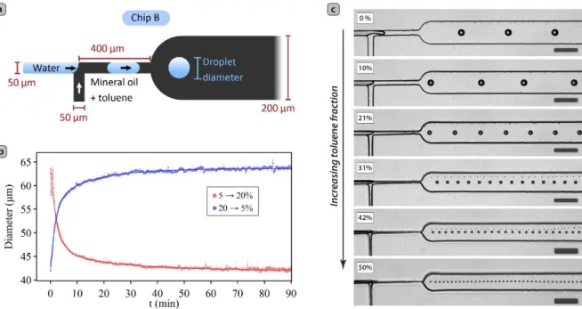
We then applied the controlled swelling process to the modulation of the behavior of a simple T-junction water-in-oil droplet generator, since we firmly believe that the control of droplet sizes in such devices is an important parameter for the microfluidic synthesis of crystalline materials. For this purpose, we started with the design of a simple T-junction droplet generator (see Figure 2a) with 50 μm wide inlets and outlets, with a height of 105 μm and which behavior is easy to rationalize. We operated the T-junction by breaking down a stream of water into droplets, via the side injection of an oil stream. Even though it is more common to inject the dispersed phase from the side channel, we chose to use this inverse configuration,[29] as it is the one used in the dual nozzle droplet pair generator that was used by Frenz et al.[30] to synthesize iron oxide nanoparticles.
To assess the time required to stabilize the size of droplets after a change in solvent concentration, the volume fraction of toluene was increased from 5 to 20% (V/V) in a single step, by adjusting the flow rates of the two stock oil syringes (see Figure S5 for the flow rate profiles). After 1.5 hours, the reversibility of the process was checked by setting the toluene
8
concentration back to 5% (i.e. reverting the two oil syringes to their initial flow rates) in a single step. Throughout this experiment, the flow of water was fixed at Qw = 100 μL/h, and the total flow of the mixture of toluene in mineral oil was kept at Qo = Qmo + Qtol = 1800 μL/h.
Upon stepping the concentration of toluene from 5 to 20%, we observed a gradual reduction in the droplet size (see Figure 2b, Figure S6, and movie S1), from an initial diameter of 64 µm to a stable diameter of 43 µm after 90 minutes. The inverse behavior occurred when the toluene fraction was stepped down from 20 to 5%, and the droplet diameter returned to its initial value of 64 µm after 1.5 hours, demonstrating the reversibility of the process, and the quality of the process is demonstrated by the good coefficient of variation (CV) after
stabilization (averaged over one minute) that is invariably in the 0.7-1.1% range (see Figure S7). In both cases, the variation of the droplet size with time does not follow a single
exponential decay/growth but instead follows very-well a bi-exponential model, suggesting the co-existence of at least two physical phenomena, with time constants of the order of 2 and 15-20 min, respectively (see Table S1 for the fitted parameters). This observation, and the line-shape of the evolution of droplet sizes with time agree remarkably well with the results of Saunders et al. who showed that the dynamics of swelling of a PDMS thin film exposed to solvent vapors are the result of a double diffusion mechanism.[25] The change in solvent concentration likely contributes to some changes in both the viscosity of the oil and the interfacial tension between the dispersed and continuous phases, but this change should propagate rapidly (with a dead time of only a few seconds), while the timescale of the evolution of droplet sizes is of the order of minutes. Those combined observations likely indicate that the geometrical changes induced by swelling are the predominant cause of the evolution of droplet sizes in our T-junctions.
A stabilization time of 30 minutes can be considered quite long for some applications, but the swelling process can be made faster when required. Indeed the swelling kinetics are the result of diffusion processes, and depend essentially on the gradient of concentration at the
9
fluid/PDMS interface. To accelerate the process, it is thus possible to flow a high concentration of swelling agent for a short amount of time (to cause an overshoot of the swelling process) and to stabilize it by flowing subsequently a lower concentration of swelling agent. As a proof of concept, we flowed an oil mixture containing 50% of toluene in a model chip for 3 minutes and then stepped the concentration down to 30%. With such a protocol, we could stabilize the droplet size in about 8 minutes (see Figure S8) including a dead time of almost 2 minutes. With optimized dead times (i.e. minimizing dead volumes) this
methodology could be coupled to PID regulation to stabilize droplet sizes at will in only a few minutes.
To demonstrate the effective range in droplet sizes that swelling-induced deformations can have on the performance of this chip, we adjusted in situ the concentration of toluene in the oil stepwise from 0 to 50% (V/V) in 20 steps, every 30 minutes (by adjusting the
respective Qmo and Qtol values) while keeping the total flow rates of water and continuous
phase constant (Qw = 30 µL/h and Qo = 1800 μL/h, respectively). As expected, the width of
the channels, and the size of the droplets, reduce gradually upon increasing the concentration of toluene (see movie S2), as shown in Figure 2c (for the size distribution histograms see Figure S9). The droplet diameter was reduced from 53 µm with pure mineral oil to about 14 µm for a continuous phase containing 50% (V/V) of toluene, corresponding to a ca. 50-fold reduction in volume. This is comparable in performance to other more sophisticated
methods.[14]
While we wanted here to demonstrate the broad range of droplet sizes that could be achieved with a given starting chip configuration, it is worth noting that this is done by a simple adjustment of flow rates of two oil mixtures that are mixed in situ. Using low concentrations of toluene, this should allow to produce small changes in the channel geometries, and could therefore be used for the active, dynamic regulation of arbitrarily selected droplet sizes on demand. The droplet diameter is a complex function of the
10
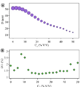
compound effects of changes in the geometry of the channels, the viscosities of the fluids and the interfacial tensions between them. In the present case, in particular, mineral oil is far more viscous than toluene, but the reduction in viscosity occurring with increasing concentrations of toluene should decrease the capillary number, which would result in greater droplet sizes, while the concomitant decrease of the channel dimensions should increase the flow velocity, and favor smaller ones. Taking into account those non-linear contributions to droplet sizes, it is therefore not surprising that the droplet diameter does not present a simple trend with the toluene concentration (see Figure 3a). It is worth noting however that we observed similar trends (see Figure S10) using petroleum ether or xylene as swelling agents. The quality of the droplet generation is essentially unaffected by the deformations of the chip, and we observed no significant change in the dispersity index (DI) also called coefficient of variation (CV) of the droplet diameter in our experiments (see Figure 3b). For all of the concentrations we studied, the DI is quite good, and lies between 1 and 2%, with a few outliers reaching almost 3%, which is similar to the values reported in co-flow (3%),[31] and flow focusing (5%)[32] geometries. This mono-dispersity in droplet sizes will be crucial to perform detailed studies of size-dependent effects in segmented-flow syntheses. Despite the complex, non-linear trend relating solvent concentration and droplet sizes, and despite the fact that many parameters (with potentially limited reproducibility) are likely to affect the magnitude of the
deformations involved (and thus the variations in droplet sizes) it is very easy to adjust the relative flow rates of the two stock solutions, and this method therefore constitutes a simple, empirical tool to modulate the droplet sizes at will.
2.4. Assessment of reliability and influence of some parameters
In order to use this method for practical applications it is highly desirable to know how a few experimental parameters such as backpressure/flow rates, temperature, chip height, chip
11
cycling history, or even the use of surfactants, can affect the swelling behavior. To address those points, we performed a series of complementary experiments.
We first wanted to establish the robustness of the swelling behavior with extensive cycling, and after extreme deformations. To test that, we used a freshly made 105 µm high chip, used it to generate droplets at a 20% toluene content (Qoil = 1800 µl/h, Qw = 100 µl/h) and
subjected it to 10 swelling and de-swelling cycles of 30 minutes each by alternating
concentrations of toluene of 0 % and 20% (Qoil = 1000 µl/h and Qw = 0 µl/h, see movie S3).
After those cycles, we again generated droplets at a 20% toluene content (Qoil = 1800 µl/h, Qw
= 100 µl/h). The size distributions of the droplets generated before and after extensive chip cycling (see Figure S11) are essentially identical, in terms of both average values and standard deviations.
We then wanted to assess the reversibility of the swelling process when subjecting the chips to extreme deformations. To do that we subjected that same chip to an oil mixture containing 50% of toluene for 30 min (Qoil = 500 µl/h). In those conditions, the chip essentially collapsed
and opened again when flowing pure mineral oil (see movie S4). Even in those extreme conditions there is no significant difference between the chip geometries before, and after deformation (see Figure S12).
Our droplet-based experiments were performed with flow rates of viscous oil solutions of 1800 µl/h, and with chip heights of 105 µm. While those flow rates are in typical ranges for microfluidic droplet generators using mineral oil, it is legitimate to wonder if the pressure drop across the chips caused by such high flow rates and the chip height (which in turns affects the pressure drop) affect significantly the swelling rates. To test the influence of the chip height on the swelling process, we fabricated fresh chips with heights of 33, 50, 67 and 105 µm, and subjected them to identical experiments. More precisely, we flowed mixtures of oil with a toluene concentration varying stepwise from 0-40% in 10% increments (Qoil = 1000 µl/h), and recorded the stable chip geometries after a stabilization time of 30 min. The
12
results of those experiments are summarized in Figure S13. To our surprise, but in retrospect unsurprisingly, the height of the chips matter significantly for the swelling behavior. As a general trend, the stable channel deformations at a given concentration of swelling agent decrease with decreasing channel height. This is likely the result of mechanical stress in the chips. Indeed the mechanical constraints in the PDMS chip contribute significantly to limit its deformations, and with decreasing channel heights, it seems reasonable that the mechanical stress opposing lateral deformation should increase, and thus the lateral strain caused by swelling is decreased. A corollary to those results is that the form factor of the cross section can matter, as it would alter the balance of mechanical stresses in different directions, and thus flat channels (such as the 35µm×50µm nozzles) would behave slightly differently than square or circular channels (such as the 50µm×50µm nozzles) and also differently from the tall form factor cross sections (such as the 105µm×50µm nozzles).
Still thinking about the importance of mechanical constraints, to test the effect of different pressure drops on the chips swelling, we performed comparative experiments by subjecting a 105 µm chip to flows of oil mixtures containing 0 and 20% of toluene, and at flow rates of 0-2000 µl/h. The effect of the differences in pressure drop across the devices on both swollen and un-swollen equilibrium geometries after 30 minutes stabilization are minimal (see Figure S14).
Another reproducibility issue could arise from the use of surfactants. We did not initially use any as we usually perform reactive flow chemistry in our droplet microfluidic chips, and surfactants are often a source of contamination of the reaction product. However, one could think that surfactants could have the ability to adsorb on the channel walls and may have an effect on the swelling solvent’s absorption kinetics in the PDMS. To check those potential effects, we therefore used a 105 µm high chip and subjected it to 1000 µl/h of a mixture of oil containing 0-40% of toluene and to which we added 2 v/v% of Span 80 (a surfactant typically used for the microfluidic generation of water droplets in mineral oil). We compared the
13
equilibrium geometries after 30 minutes to those measured without surfactant (see Figure S15), and could not observe any differences between the two data sets. We therefore used the same chip, at a constant Span 80 concentration of 2%, to generate streams of water in oil droplets for concentrations of toluene ranging from 0-40% (Qoil = 1000 µl/h, Qw = 100 µl/h)
and showed that as expected, the droplet sizes can be controlled by controlling the amount of toluene in the oil mixture (see Figure S16 and movie S5).
Finally, for some applications, one might want to adjust the process temperature. Since the swelling of PDMS by toluene is controlled by a diffusion process, temperature should matter. As a first approach, Fick’s laws are temperature independent, but the diffusion coefficient D should be temperature dependent, and in fact, the Stokes-Einstein equation would predict a linear dependency with the thermal energy kBT and thus a linear trend with temperature. The mechanical properties of PDMS (and especially its Young’s modulus) should also be
temperature dependent. One could therefore expect that with decreasing temperatures, the Young’s modulus of PDMS should increase, and the diffusion coefficient for the swelling solvents (such as toluene) should decrease as well. We expect therefore that decreasing the temperature will lead both to an increase in stiffness of the PDMS and to slower diffusion rates, which would jointly slow down the swelling process and decrease its magnitude.
2.5. Application to reactive flows
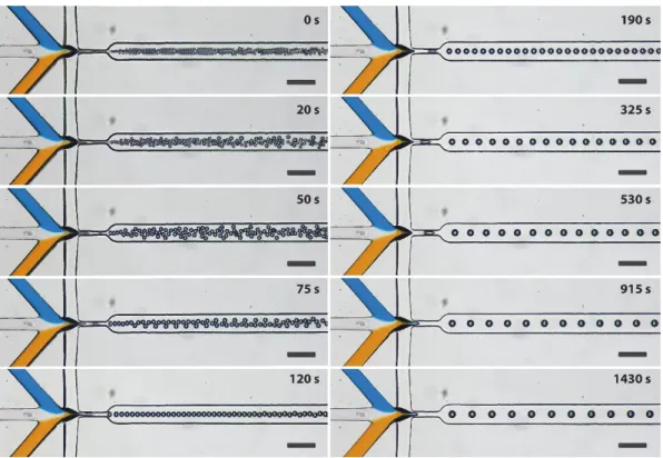
To illustrate the usability of this method for reactive flows, we first used a known flow-focusing droplet generator used previously for the synthesis of nanoparticles of a spin crossover coordination polymer[3] (see Figure 4 and movie S6). The volume of the droplets produced by such a chip could be changed by almost two orders of magnitude, in a few minutes, by varying the toluene concentration by only 20% (V/V) of toluene in the mineral oil and with no modification whatsoever to the other parameters dictating the reaction conditions (concentration of the reagents, flow rates, temperature, etc.).
14
With some optimization in chip geometries and operating conditions to attain optimal stabilities even with very small droplets, this experimental capability will be a great tool for the fast throughput screening of the influence of droplet-sizes on the nature and morphology of the synthesized materials. As a proof of concept experiment, we applied it here to the synthesis of nanoparticles of Prussian blue analogues (PBA) of formula
RbxMn[Fe(CN)6](x+2)/3, a well-known family of coordination polymers with a great variety of interesting properties,[33] and exhibiting a clear tetragonal morphology. For this purpose, we used yet another device geometry that consisted in a flow-focusing nozzle similar to the one used by González et al.,[3] but that presented a serpentine channel after the nozzle to promote an efficient mixing of the reagents inside the droplets. We operated this device with a
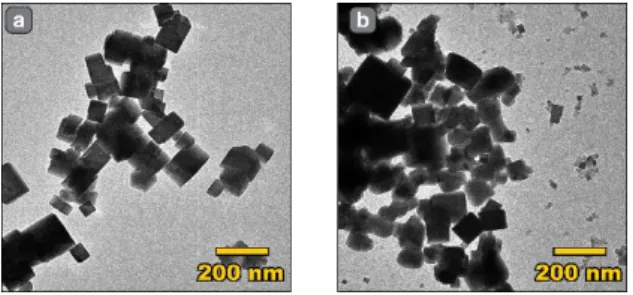
concentration of toluene of 0 and 20% in mineral oil, which yielded (after stabilization) droplets of reaction with diameters of 78 and 48 µm, respectively. The effect of swelling can be clearly seen in Figure S17. Both reaction conditions (with and without swelling) afforded nanoparticles with similar dimensions and FTIR spectra (see Figure 5, and Figure S18). Upon careful examination though (see Figure S19) for small droplets, the chip produced a bimodal nanocrystals population with the appearance of a prominent population of very small particles when compared to the non-swollen geometry. While the origin of those differences is
unknown at this stage, one can suppose it is due to modifications in the relative influence of the characteristic mixing time, which is known to vary with the relative size of the droplets and the channel width,[34] and the characteristic diffusion time of the reagents that should be shorter for smaller droplets. This preliminary result illustrates the compatibility of our method with chemical synthesis, opening perspectives for the tuning of particle sizes in optimized conditions. In the future, with more elaborate chip designs, our method will allow us to study droplet-size/property correlations, to establish which systems are strongly affected by droplet sizes and which ones are not, and to elucidate the reasons behind those differences.
15
3. Conclusion
In conclusion, we present here a simple, reversible, in situ method to adjust the geometry of microfluidic chips via the control of geometrical changes arising from the swelling of its PDMS parts. While PDMS swelling is generally considered as an issue to be avoided, taking into account the expected magnitude of swelling while designing microfluidic chips can lead to practical applications of this phenomenon. In particular, we used it to modulate the size of droplets generated in three different types of microfluidic nozzles and showed that it can be applied to real synthesis conditions. We showed that the change in droplet diameter are essentially related to the geometrical deformation of the chip, yielding significant changes in droplet volumes. This method presents a series of advantages: i) it does not require the use of surfactants or changes of temperature (that would affect the reactions occurring inside the droplets), ii) the equipment requirements are minimal (it only requires the use of an additional syringe pump), iii) it allows to decrease droplets sizes without increasing the flow rate of the viscous continuous phase (which would otherwise increase the pressure drop and thus the likelihood of chip failure) and iv) it does not lead to an increase in size dispersion.
We expect that further development and combination with active droplet breakup techniques could extend significantly the range of droplet sizes generated with a single chip design. Combining it with a live image analysis feedback mechanism, it could offer an easy route to producing a given droplet size on demand. It should be easy to adapt to dual emulsion nozzles to carry on reactions based on droplet merging, and finally, it should provide an easy access to the preparation of ultra-small droplets as highly confined micro-reactors. In a more general sense, we expect that integrating swelling into design should allow to adjust the function of many different types of chips exhibiting geometry-driven functions.
4. Experimental Section
Microscopy and image analysis: Chips A and B were mounted on a Leica DM LM
16
study of controlled deformations and with a DFK 33UX252 camera (The Imaging Source) for the other experiments. Automated image analysis was performed using ImageJ.
Chip preparation: The microfluidic chips were fabricated using standard soft lithography
replica molding methods. First, masters were patterned on silicon wafers by photolithography with SU-8 (Microchem) photoresist according to the manufacturer’s specifications. The resist films were spin-coated using a SPIN-150 spin coater (SPS-Europe), exposed with a UV-KUB 2 (KLOE) light source through high-resolution soft masks (SELBA), and developed
according to the manufacturer’s specifications. The masters were silanized by exposure to trichloro(1H, 1H, 2H, 2H-perfluorooctyl)silane (Sigma-Aldrich) vapours in a vacuum
dessicator. The height of the fabricated masters were checked with a mechanical profilometer (Dektak 6M, VEECO). A 10:1 mixture of SYLGARD 184 silicone elastomer base and curing agent was prepared and poured on the masters to achieve PDMS layers of 3-4 mm in
thickness, and the PDMS was cured in the oven at 80°C for 2 hours. Afterwards, PDMS chips were diced, adhesive tape was applied to the face with the setoff to avoid dust contamination in the channels, and inlet and outlet holes were drilled in the chip using a 1.2 mm Harris UNI-CORE biopsy punch. Pre-cleaned glass slides (CORNING, 75 x 50 mm) were coated with a thin film of a 10:1 PDMS/curing agent mixture by spin-coating at 2000 rpm for 60 s with an acceleration of 500 rpm/s. The PDMS-coated glass slides were partially cured in the oven at 80°C for 10 minutes. The bulk PDMS chips were released form the adhesive tape and put in gentle contact with the PDMS-coated face of the glass-slides. Finally, the assembled chips were annealed in the oven at 80°C for one hour.
Chip operation: The fluids were dispensed to the chips with 10.0 mL and 2.5 mL ISL glass
syringes mounted on low-pressure syringe pumps (neMESYS 290N modules, with 29:1 and 14:1 gearboxes, respectively) for oil and water phases, respectively. Mineral oil (light, Sigma-Aldrich) and a 1:1 mixture of toluene (98%, J.T. Baker) and mineral oil were combined before entering the chip in a Tee connector (Valco) and mixed by a PEEK frit of 2 μm
17
porosity mounted on a low pressure ETFE union assembly (IDEX Health & Science) as shown in Figure S20. The microfluidic system was connected with PFA tubings (IDEX Health & Science) using tubing with an internal diameter (ID) of 500 μm and an outer diameter (OD) of 1/16” from the oil syringe to the T-connector and from the outlet of chip B to the waste container, and tubings with 0.01” ID for all other fluidic connections.
To reduce pulsations and acoustic pollution, a custom-made pulsation dampener PDMS chip was used between the water syringes and the chips inlets, as shown in Figure S21. The pulsation dampener was composed of three parts: an inlet filter, a 50 mm × 1 mm channel (that due to the flexibility of PDMS, acts as a small capacitor) and a 50 cm × 90 μm channel (acting as a flow resistor). This chip was prepared as described above, and was then heated on a hot plate at 100°C for 3 min, the tubes were connected to the inlet and outlet and it was heated again on a hot plate at 130°C for 60 min.
Synthesis: Two reactant solutions were prepared: RbCl (90.1 mg, 0.75M) and MnCl2 (18.9
mg, 0.15M) were dissolved in 1 ml of DI water (reactant A), and RbCl (90.1 mg, 0.75M) and K3Fe(CN)6 (49.3 mg, 0.15M) were dissolved in 1 ml of DI water (reactant B). Both reactant solutions were co-injected in the flow focusing junction shown on Figure S17 together with a stream of pure DI water. The flow rates were QA = QB = 150 µl/h, Qwater = 200 µl/h, and Qoil = 2550 µl/h. The mixture exiting the chip was collected, centrifuged at 3500 r.c.f. for 2 minutes, washed three times with petroleum ether to remove the oil, and washed with ethanol and acetone twice to remove the excess water and salts.
Supporting Information
Supporting Information is available from the Wiley Online Library or from the author.
18
This work was supported by the Mexican government and the National Council of Sciences and Technology (CONACyT, program 073096, announcement 291060) and the French National Research Agency (ANR) Investment for the Future Program IdEx Bordeaux (ANR-10-IDEX-03-02). We would also like to thank S. Marre and J.-C. Baret for their support and kindness with access to microfabrication facilities and F. J. Valverde Muñoz for enriching discussions. PLACAMAT is also acknowledged for the use of the TEM facilities.
Received: ((will be filled in by the editorial staff)) Revised: ((will be filled in by the editorial staff)) Published online: ((will be filled in by the editorial staff))
References
[1] G. M. Whitesides, Nature 2006, 442, 368.
[2] M. Faustini, J. Kim, G. Jeong, J. Y. Kim, H. R. Moon, W. Ahn, D. Kim, J. Am. Chem.
Soc. 2013, 135, 14619.
[3] J. H. González-Estefan, M. Gonidec, N. Daro, M. Marchivie, G. Chastanet, Chem.
Commun. 2018, 54, 8040.
[4] L.-H. Hung, K. M. Choi, W.-Y. Tseng, Y.-C. Tan, K. J. Shea, A. P. Lee, Lab Chip
2006, 6, 174.
[5] B. Zheng, J. D. Tice, L. S. Roach, R. F. Ismagilov, Angew. Chem. Int. Ed. 2004, 43, 2508.
[6] W. J. Duncanson, T. Lin, A. R. Abate, S. Seiffert, R. K. Shah, D. a Weitz, Lab Chip
2012, 12, 2135.
[7] P. Laval, A. Crombez, J.-B. Salmon, Langmuir 2009, 25, 1836.
[8] H. Shi, Y. Xiao, X. Huang, Y. Bao, C. Xie, H. Hao, Ind. Eng. Chem. Res. 2018, 57, 12784.
[9] P. Zhu, L. Wang, Lab Chip 2017, 17, 34.
19
[11] X. Chen, T. Glawdel, N. Cui, C. L. Ren, Microfluid. Nanofluidics 2015, 18, 1341. [12] V. van Steijn, C. R. Kleijn, M. T. Kreutzer, Lab Chip 2010, 10, 2513.
[13] J. D. Tice, A. D. Lyon, R. F. Ismagilov, Anal. Chim. Acta 2004, 507, 73. [14] C. A. Stan, S. K. Y. Tang, G. M. Whitesides, Anal. Chem. 2009, 81, 2399. [15] S. L. Anna, H. C. Mayer, Phys. Fluids 2006, 18, 121512.
[16] S. H. Tan, B. Semin, J.-C. Baret, Lab Chip 2014, 14, 1099.
[17] D. R. Link, E. Grasland-Mongrain, A. Duri, F. Sarrazin, Z. Cheng, G. Cristobal, M. Marquez, D. A. Weitz, Angew. Chem. Int. Ed. 2006, 45, 2556.
[18] A. Bransky, N. Korin, M. Khoury, S. Levenberg, Lab Chip 2009, 9, 516. [19] J. Xu, D. Attinger, J. Micromechanics Microengineering 2008, 18, 65020.
[20] H. Willaime, V. Barbier, L. Kloul, S. Maine, P. Tabeling, Phys. Rev. Lett. 2006, 96, 4. [21] Y. Zeng, M. Shin, T. Wang, Lab Chip 2013, 13, 267.
[22] J.-H. Choi, S.-K. Lee, J.-M. Lim, S.-M. Yang, G.-R. Yi, Lab Chip 2010, 10, 456. [23] L. Paseta, B. Seoane, D. Julve, V. Sebastián, C. Téllez, J. Coronas, ACS Appl. Mater.
Interfaces 2013, 5, 9405.
[24] M. Gonidec, J. Puigmartí-Luis, Crystals 2018, 9, 12.
[25] J. E. Saunders, H. Chen, C. Brauer, M. Clayton, H. P. Loock, Soft Matter 2018, 14, 2206.
[26] R. Dangla, F. Gallaire, C. N. Baroud, Lab Chip 2010, 10, 2972. [27] J. N. Lee, C. Park, G. M. Whitesides, Anal. Chem. 2003, 75, 6544.
[28] M. Kim, Y. Huang, K. Choi, C. H. Hidrovo, Microelectron. Eng. 2014, 124, 66. [29] J. H. Xu, G. S. Luo, S. W. Li, G. G. Chen, Lab Chip 2006, 6, 131.
[30] L. Frenz, A. El Harrak, M. Pauly, S. Bégin-Colin, A. D. Griffiths, J. C. Baret, Angew.
Chem. Int. Ed. 2008, 47, 6817.
[31] P. B. Umbanhowar, V. Prasad, D. A. Weitz, Langmuir 2000, 16, 347.
20 1067.
[33] S. Ohkoshi, H. Tokoro, K. Hashimoto, Coord. Chem. Rev. 2005, 249, 1830. [34] M. Muradoglu, H. A. Stone, Phys. Fluids 2005, 17, 073305.
21
Figure 1. (a) Simplified geometry of the test chip used to test the effect of solvent
concentration on the swelling of PDMS micro-structures of different critical widths. (b) Microchannel deformations for w0 = 50, 120, 250 and 520 µm. The red lines correspond to the best linear fits to the experimental data. (c) Response coefficient Δδw for the swollen test-chip microstructures as a function of their initial structure dimension w0, the error bars correspond to a 95% confidence interval.
22
Figure 2. (a) Design of the T-junction droplet generator used for the study of the influence of
swelling on droplet sizes, (b) time-dependent droplet sizes upon stepping up (red) and down (blue) the concentration of swelling solvent in the continuous phase (the continuous lines correspond to the best fits to a bi-exponential model), and (c) micrographs of the chip showing the droplets generated in steady-state, at different concentrations of swelling agent
23
Figure 3. Evolution of (a) the droplet diameter and (b) the dispersity index (or coefficient of
variation) with the concentration of toluene CT. In (a), the size of the marker is proportional to the droplet diameter for easy visualization.
24
Figure 4. Evolution of water droplet sizes generated in a flow-focusing nozzle caused by
de-swelling a pre-swollen chip by adjusting the concentration of toluene in mineral oil. The flow rates were: Qoil = 2500 µl/h, Qw = Qblue + Qwhite + Qorange = 150 µl/h, and Qblue = Qwhite = Qorange = 50 µl/h. Inlets were coloured using food-colorant. The scale bars correspond to 200 µm.
25
Figure 5. TEM images of the PBA nanoparticles produced with normal (a) and swollen (b)
26
A simple method to tune the geometry and function of microfluidic chips based on PDMS swelling is presented. This simple and efficient approach is a great asset for droplet microfluidics synthesis, where droplet sizes are difficult to disentangle from other experimental variables. Additionally, it could be useful to tune the behavior of other microfluidic chips with geometry driven functions.
Microfluidics
Juan H. González-Estefan, Mathieu Gonidec,* Thi Thiet Vu, Nathalie Daro, and Guillaume Chastanet
In situ fine-tuning of microfluidic chips by swelling and its application to droplet microfluidics
ToC figure ((Please choose one size: 55 mm broad × 50 mm high or 110 mm broad × 20 mm high. Please do not use any other dimensions))