-4
The Contact relationship between an large orogenic ultramafic massif
and its surrounding units: Beni Bousera northern Morocco
MASSACHUSETTS INSTIT
by OF TECHNOLOGY
Alison Piasecki
OCT 24
?017
LIBRARIES
ARCHIVES
Submitted to the Department of Earth, Atmospheric and Planetary Sciences in Partial Fulfillment of the Requirements for the Degree of
Bachelor of Science in Earth, Atmospheric and Planetary Sciences at the Massachusetts Institute of Technology
May 8, 2009
Copyright 2009 Alison Piasecki. All rights reserved.
The author hereby grants to M.I.T. permission to reproduce and distribute publicly paper and electronic copies of this thesis
and to grant others the right to do so.
Author
Si
Certified by_
Accepted by_
)nature
redacted
'71 Department of Earth, Atmospheric and Planetary Sciences
Signature redacted.
Signature redacted_
May 8, 2009 Oliver Jagoutz Thesis Supervisor Samuel Bowring Chair, Committee on Undergraduate ProgramThe euthr hrey grents to MIT permisson to
reproduce
and to distribute publicly paper and
UTE
MITLibraries
77 Massachusetts Avenue Cambridge, MA 02139 http://Iibraries.mit.edu/ask
DISCLAIMER NOTICE
Due to the condition of the original material, there are unavoidable
flaws in this reproduction. We have made every effort possible to
provide you with the best copy available.
Thank you.
The following pages were not included in the
original document submitted to the MIT Libraries.
This is the most complete copy available.
Acknowledgments
I would like to thank my advisor Professor Oliver Jagoutz for everything that he has taught me and for helping me so much. I would also like to thank my other professors at MIT specifically Professor Tim Grove and Sam Bowring for their enormous help throughout my time as an undergraduate. I would also like to thank Nilanjan Chatterjee for his extensive help with the electron microprobe, and Jessica Stanley, Kyle Bradley, Jay Barr, Michael Krawczynski, and Christ Till for answering all my questions along the way.
Table of contents
Abstract ... I
Acknow ledgem ents ... 2
Table of Contents ... 3
List of Figures and Tables ... 4,
Introduction ... 5
Geologic Setting ... 5
M odels of Em placem ent for the Ultram afic M assifs ... 7
Results ... 10
Regional Geology ... I ... 10
Detailed Structure along the Profile ... 13
Petrology along the Profile ... 17
Discussion ... 23
Regional Structure ... 23
Pressure and Tem perature Estim ates ... 25
Em placem ent of Beni Bousera ... 26
Conclusion ... 30
Future Research ... 31
References ... 32
List of Figures and Tables
Figure 1: Regional map
Figure 2: Emplacement models Figure 3: Map of Beni Bousera Figure 4: Profile through gneiss Figure 5: Fold in gneiss
Figure 6: Foliation poles Figure 7: Lineation
Figure 8: Leucocratic areas Figure 9: Brittle structures Figure 10: Felsic area Figure 11: Sample 29
Figure 12: Garnet composition
Figure 13: Plagioclase ternary diagram Figure 14: Sample 35
Figure 15: Sample 36 Figure 16: Sample 37
Figure 17: Graph of MnO vs. CaO Figure 18: Schematic cross section
Figure 19: Unfolded schematic cross section
Figure 20: Pressure and temperature estimates for sample 29 Figure 21: Pressure and temperature estimates for sample 35 Figure 22: Pressure and temperature estimates for sample 37
Table 1: Weight percent analyses Table 2: Cation analyses
Introduction
The Beni Bousera ultramafic massif is an orogenic lherzolite in northern Morocco, and is part of a large series of ultramafic massifs (Chalouan and Michard, 2004). Like all orogenic lherzolite the method of emplacement into the upper crust is not well understood (Reuber et al., 1982). In this thesis, the Filali gneiss, Kinzingite gneisss, and leucocratic dikes were studied in order to find out their contact relationship with the ultramafic body. A detailed cross section was completed starting in the south, 2 kilometers from the contact, up to the contact. The detailed structures of the exposed gneiss along a transect towards the contact between the host gneiss and ultramafic was studied. Additionally, pressure and temperature estimates on three samples along the transect has been conducted.
Geologic Setting
The Rif Mountains, the westernmost edge of the Alpine Belt, and the associated Alboran basin is very complex and no consensus exits on the origin (Fig 1). From south to north there are three major units of thrust sheets: The first major unit is the external zone, which is a fold and thrust belt composed of the paleomargin sediments of Africa and Iberia. The next is the Maghrebian Flysch nappes situated north of the external zone and consist of multiple internal thrust nappes of oceanic and transitional crust from Ligurian-Maghrebian Ocean. This ocean formerly connected the Atlantic and Alpine Oceans (Chalouan and Michard, 2004). The innermost unit, which is against the Mediterranean coast, is the internal zone. This unit of continental origin, mainly carbonate, metasediments and clastic deposits, was displaced westward several hundred kilometers (Chalouan and Michard, 2004); (Michard et al., 2008).
The Beni Bousera ultramafite are exposed within the internal zone. The Beni Bousera massif is part of a belt of ultramafic massifs that extend into southern Spain including the well known Ronda ultramafic massif(Loomis, 1972) and outcrop in the orocline at the western edge of the Alpine belt (Chalouan and Michard, 2004).
Guada/guivir Ba sin
5
40
. . . .Grada
Cadiz
*0 3560
Waga
Ar
wait-of
Gibraltar--Ter i ars -ODP 0
P11-jr
0
Ceta
DSDP 12 - (Sebta)A 35* - AlboranI 0 -7igepubOrall
...
IHoceima .4 BKeni
...
Temns.
+ab+%.
.
+ + + +
+
4
A - .. As ... ... _ __ __ __ __ritraif
1Mesorif. Rif nappes
Alptarride-Sebtide nappes
SForeland
baement a
a.
BenI Malek serpeninites a
-
a: Ronda, B. Bousora peridotites
Meseta and Atlas
Sub-BetcZone
a
Nevado-Filabrides corplex
cover series
b
a: Mulhacen: b:
Veleta
Foredeep basins
.
aMaghrebian Flyschs
^Z
Neogene volcanics
Detached Atlasic "Dorsele calcaire& units Main thrust contact (onshore)
cover at Prerif
towl
1--J-ale-al maide Fold axis. norrnal fault (offshore'rI
Prerif
rp
iape-
dReverse
fault front of Gibraltar
nappes
arc
unils
(offhore)
Mocene thrust
<==
Miocene extensional
Front of Belc.-Rif accrelionary
transport direction
unit transport direction
wedge (ciistostrome front)
One theory is that the Rif mountains are the result of a collisional zone which is unrelated to subduction (Chalouan and Michard, 2004; Kornprobst and Vielzeuff, 1984). A second theory involves one subduction zone dipping northwest from Gibraltar to the Apennines (Zeck, 1996) (Chalouan and Michard, 2004). The third and final theory is that there were two subduction zones, one dipping south east related to the Alpine Belt, and another dipping northwest related to the Apenninic-Maghrebian area. The southern subduction zone is also thought to have undergone extensional collapse due to convective removal of the lithospheric mantle root as well as slab break-off (Michard et al., 2002)
(Chalouan and Michard, 2004). The most commonly excepted model is that there were two subduction zones, as it is the model which most fully explains the Rif Mountains' connection with the Alpine
Orogeny, and extensional collapse during the Miocene (Chalouan and Michard, 2004).
No consensus exits on the emplacement mechanism of the ultramafic massifs. The aim of this thesis is to document the detailed contact relationship between the ultramafite and host gneisses to better constrain their emplacement.
Models of Emplacement for the Ultramafic Massifs
There are three different models that are debated for the emplacement of both the Beni Bousera and Ronda ultramafic massifs: (1) a mantle diapir (Loomis, 1972), (2) injection of mantle material within the lower crust along thrust faults (Reuber et al., 1982), and (3) deep detachment faults reaching in the mantle during extension followed by a compressional event that produced a complex stack of nappes (fig. 3) (Platt, 2007; Platt et al., 2003b).
Early studies in both the Beni Bousera Massif and within the Ronda massif concluded the peridotite was emplaced as a diapir ascending from the mantle (Kornprobst and Vielzeuff, 1984)
(Loomis, 1972). During extension in the Miocene the lower crust was thinned, allowing for the mantle to ascend. A diapir continued to ascend into the lower crust because it was hotter than the surrounding
(a) (C) ---(1)
~--- .... -(3) ... w ... ... . ... - --- ---- -- -.-- - ---External Thrust Belt
(6)
Figure 2 Models of emplacement of the massif. For all models pale pink is crust, dark pink is kinzingite, pale green is mantle, and dark green represents the part of the mantle that becomes the massif (a) represents the diapir model (Loomis 1972;
Kornprobst and Veilzeuf 1984) that occurs when the crust thins and a mantle diapir rises; (b) is the model of a peridotite lens thrust into the lower crust with thrust faults represented in red (Reuber et al. 1982); (c) is Platt's model of detachment faults coupled with thrust nappes (Platt et al. 2007). The dashed lines represent foliation, and the dark line represents a fault. In
(1) a low angle normal fault cuts through the mantle during extension, (2) has another low angle detachment fault, (3) shows the topography of the Moho created by the faults, and the topography of the foliation, (4)
represents when a low angle normal faults emplaces a sliver of mantle
material within the surrounding lower crustal rocks, (5) is the same as (4) just at half the scale, (6) shows how putting a thrust fault through the detachment structures creates a series of thrust nappes with an ultramafic body within the stack.
...-
I
... -7 ... . . . .. . . ... iw, (2) ... --- ---(4).result the diapir thinned out and dragged upwards the surrounding lower crustal metapelite gneiss. The major evidence for this model is the extent of ductile shear within the surrounding gneiss. In locations around the Ronda massif the contact is vertically exposed, which is inferred as evidence that the relationship between the peridotite and gneiss was originally vertical like the wall of a diapir(Loomis, 1972).
Alternatively, emplacement occurred along deep reaching thrust faults juxtaposing hot mantle material next to lower crust during compression (Reuber et al., 1982). Similar to the previous model, the Reuber model suggests the Moho was relatively shallow before emplacement of the ultramafic rocks due to extension and thinning of the continental crust. The mantle was uplifted due to isostatic uplift.
But, after extension ended and compression resumed a lens of peridotite was thrust into the lower crust. The peridotite lens is not significantly hotter than the surrounding rock within this model, and therefore does not heat the surrounding rock causing contact metamorphism. The major structures surrounding the peridotite within this model are the result of extensive shearing (Reuber et al., 1982).
The third model for emplacement of the massif as proposed by Platt (Platt, 2007) invokes a series of thrust and normal fault. Platt and co-workers propose that during the extensional episode in the Miocene a series of detachment faults placed a sliver of peridotite within the lower crust (FIG 2). After extension finished and compression resumed, the peridotite and surrounding lower crustal units were brought up to the surface in a complicated series of thrust nappes associated with the alpine orogeny (Platt, 2007).
Currently, all three emplacement model are discussed and no consensus exits. The overall evidence is inconclusive, and currently does not eliminate any model. The geochronological data also yields conflicting results. U-Th-Pb dating of monazite crystals within the Kinzingite gneiss surrounding the peridotite massif yields a mean age of 284 27 Ma, which is believed to be associated with the emplacement of the metasediment into the lower crust (Montel et al., 2000). Other data includes K-Ar
ages of biotite in schists which yields 20.7 Ma (Loomis, 1975), and is believed to date the emplacement of the massif within the lower crust. Most other dates also cluster around 20 Ma, and are believed to be
related to emplacement (Montel et al., 2000) but do not restrict the method of emplacement.
Results
Regional Geology
The Beni Bousera massif is a peridotite body surrounded by metapelite gneiss from the lower crust (Fig 3) (Kornprobst and Vielzeuff, 1984). The main composition of the massif is a spinel lherzolite, associated with minor amounts of dunite and pyroxenite (Kornprobst and Vielzeuff, 1984). Pyroxenites in part preserve graphite pseudomorphs after diamond indicating equilibration at high mantle pressures
(Slodkevich, 1983);(Pearson et al., 1989). The outer rim of the peridotite body has a serpentinite layer which varies in thickness up to several tens of meters due to alteration (Kornprobst and Vielzeuff, 1984).
Surrounding the ultramafics is gneiss. There are two gneisses: the Kinzingite which is against the contact and the Filiali which surrounds the Kinzingite. The gneiss, which includes both the Kinzingite and Filali, is presumed to be dominantly derived from a sedimentary protholith that was metamorphosed in the lower crust. Mineralogicaly the gneiss is composed of garnet + plagioclase + kyanite + potassium feldspar + biotite + quartz (Kornprobst and Vielzeuff, 1984). Locally it has a migmatitic texture defined by schlieren of leucosomes and melanosomes. The leucosomes are mainly plagioclase + quartz +
potassium feldspar + kyanite garnet tourmaline. The melanosomes are mainly composed of biotite + garnet. In general the migmatitic parts of the gneiss are more frequent towards the contact, and the relative amount of leucocratic material increases towards the contact. The gneiss is partly affected by some retrograde reactions such as kyanite transformed to sillimanite indicating cooling and other alterations of garnet + potassium feldspar + water -+ biotite + cordierite + quartz and garnet kyanite sillimanite -- cordierite + spinel + quartz (Kornprobst and Vielzeuff, 1984).
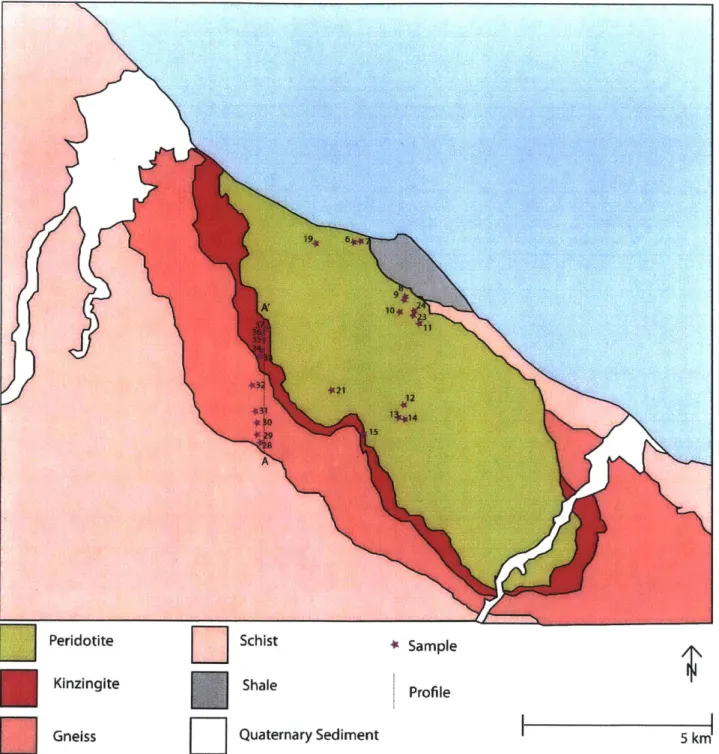
Peridotite Schist 4 Sample
Kinzingite Shale
Profile
Gneiss Quaternary Sediment 5 km
Figure 3 Map of Beni Bousera massif. Profile is from A - A', selected samples are indicated by stars, modified from Kornprobst and Vielzeuf 1984
19
AK 19I
2a
8.5 kbar 10 kbar 27 * 28 * 29* 30* 31 * 32* 33 * 34 * 35 36 37 * * *
N
900m $ >-~
-- / ouum~~-4 r -4-/~~_
I
I
Om loom 500mFigure 4 Detailed cross section along profile indicated in figure 3, dashed lines indicate foliation and structure; dashed red line is contact
between the gneiss and peridotite. Lines above profile indicate the foliation.
S
The leucocratic patches are interpreted as the result of partial melting of the gneiss. Their composition is mainly kyanite+ quartz + plagioclase potassium feldspar garnet cordierite
(Kornprobst and Vielzeuff, 1984). Besides diffuse patches and schlieren of leucosomes leucocratic dikes are found ranging in diameter of a meter to almost 100 meters within the migmatites. It is likely that the dikes are locally derived from the migmatitic host rock. Within the peridotite, especially around the edge where it has been serpentinized, similar leucocratic dikes as in the migmatites occur. It is inferred that these are derived from the surrounding gneiss due to them having the same phase assemblage found in the leucocratic zones within the gneiss. The phase assemblage reflects their high bulk aluminum content, supporting a meta-sedimentary source.
Detailed Structure along the Profile
A S-N profile was completed from point A to A' on the map starting from approximately 2km from the contact between the ultramafic massif and the gneiss northward towards the contact (Fig 4). Most of the data presented here is collected from along the profile. Observations were completed along the profile except for some of the observations of the contact which were completed elsewhere in the massif due to rather poor exposure of the contact itself along the profile.
The gneiss is strongly banded and foliated defined as the result of banding between leucocratic and non leucocratic material and the alignments of sheet silicates (biotite). The bands range in thickness from millimeter to centimeter scale. In most cases
along the profile the foliation is occasionally
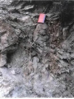
Looking Southest
isoclinally or kink folded, indicating multiple stages of Figure 5 Folded mafic zone indicating strain
deformation (Fig 5). The multiple events of top to the northwest, approximately 1 meter deformation could be related to emplacement into the lower crust, and then further emplacement into
the upper crust. Sometimes the foliation is also sheared or broken with melt intruded in the fracture, in a boudinage which indicates extension.
Overall the foliation shows a slight change in dip: In the most distal part from the contact the foliation dips and average 30 degree towards south. Towards the contact the foliation becomes progressively parallel towards the
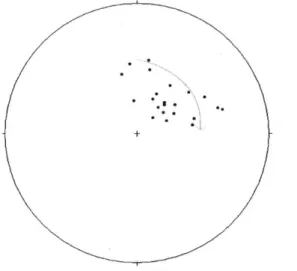
shallow dipping contact between the ultramafic massif and the gneiss (Fig 6).
The contact between the two its shallow dipping within the profile does n
Figure 7 Lineation, green and blue circles indicate the strain to the NW and SE, red circle is only found against contact
elf even so it
Figure 6 Plot of foliation poles, top center ot always have is the beginning of the contact, and the
poles move clockwise towards the contact the same shallow dip. Based on detailed mapping we
documented that the contact sometimes seems to follow the topography (shallow dip) and other times seems to strike independent of the topography (steep dip). The foliation of the gneiss does not have the same trends as the foliation within the massif. In general this structure of the massif is an anticline when viewed in cross section from the northwest to the southeast. The gneiss dips away from the contact on the profile.
Them linatin within the neiss is usuall indicaed b
the elongation of grains like quartz or augen structures created by rotated grains. There are two main groups of lineations (Fig7), one of shear sense top to the northwest and another with shear sense top to
the southeast. There are also some that lie in between with top to the southwest shear sense which all occur very close to the contact where the lineation seems to be very variable.
There are many examples of brittle structures along the profile (Fig 8). The majority of the brittle deformation is
centralized about half a kilometer from the contact with the ultramafic massif. In this area there are many small faults that cut through all the other structures in the area, and their offset
Figure 8 Brittle structures in gneiss, is generally small, (a few meters). There are no large brittle small fault with top to the right, structures. The faults exhibit top to the southeast like many of
looking west
the other brittle structures.
At the beginning of the profile 2 km from the contact there are examples of brittle structures including broken fold hinges. There are also structures a that are a combination of brittle and ductile like melt filled boudinages and small shear zones (Fig 9). These structures occurred in a less ductile regime than many of the main structures that created the foliation, but are not as brittle as the small faults which appear to be the last structures created. Brittle deformation is not the
dominant form of deformation within the gneiss. The brittle Figure 9 Leucocratic areas in gneiss, structures overprint the more dominant ductile deformation. shows both the diffuse melt patch
and more dike like structures
In addition to the brittle structures there are many ductile structures, which are the dominant form of deformation within the gneiss within 2 km of the contact. There are two major areas of ductile
-
~deformation
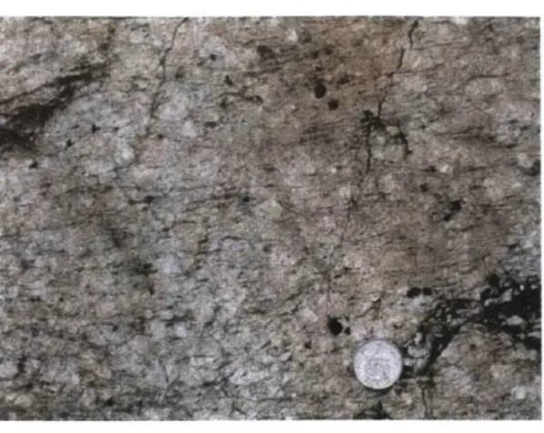
as well as overall ductile structures that arepresent throughout the gneiss. The first is a large felsic
intrusion approximately 1.5 km from the contact with the
SLeperidotite, which is a large area of felsic material. The
zone is mainly composed of plagioclase + quartz + kyanite
Figure 10 Felsic area, shows large + potassium feldspar +tourmaline minerals. The foliation tourmaline grains and penetrative foliation in felsic area is not folded at all, and the surrounding areas
show an increase in the strength of the foliation approaching the felsic zone. All structures in the area are ductile. It seems to indicate that the emplacement of the zone was very hot, and that it intruded along the foliation since it has the same strong penetrative foliation as the surrounding area.
The other area with increased ductile shear is the area against the contact with the ultramafic body. Departing the brittle area half a km from the contact, the foliation becomes increasingly strong, the brittle deformation diminishes, and the leucocratic material becomes more prominent due to distinctive banding within the gneiss. There are many large garnets that have been rotated creating augen structures indicating shear top to the northwest. Approaching the contact the garnets become
larger and the thickness in bands of leucocratic and non-leucocratic material increase up to 2 centimeters in diameter. The highest strain in the gneiss is against the contact.
The contact itself is not very well exposed along the line of the profile. The outcrop is eroded to red dirt for the Kinzingite gneiss against the contact. Continuing northward the dirt turns green and eventually there is outcrop of serpentinite. In other locations the area surrounding the contact is better exposed but a clear outcrop of the contact itself was not found. In other locations the serpentinite against the contact appears to be fractured into blocks which are in a matrix of quartz and serpentinite. It almost appears as if the serpentinite is in a breccia. The structures look very sheared right against the
the numerous quartz veins and leucocratic dikes that surround the area. The contact, although there is some brecciated serpentinite, has many ductile structures on both sides of it.
The contact is the most important part of the profile in order to gain insight into a potential mechanism of emplacement for the ultramafic massif. Due to its poor exposure and ambiguity the rest of the profile through the gneiss can provide the information needed to study the relationship between the gneiss and the peridotite.
Petrology along the Profile
Thirty-seven samples were taken in order to look at the petrology of gneiss and the leucocratic veins both within the gneiss and within the peridotite. The samples were made into thin sections and analyzed with both a petrographic microscope and an electron microprobe. The microprobe used was in Professor Timothy Grove's laboratory at MIT, and it is a five-spectrometer JEOL 733 Superprobe.
Analyses were done using a 15kV accelerating voltage and 1OnA beam current. The probe was calibrated with natural standard mineral samples. The samples that were studied in depth on the microprobe and with a petrographic microscope were from the profile. Both gneiss, and leucocratic veins within the gneiss were studied. Samples were selected both from the beginning of the profile, 2 kilometers from the contact, and from within 50 meters of the contact.
The first sample analyzed along the profile was sample number 28 which is a gneiss from approximately 2 kilometers from the edge of the contact. This sample contained potassium feldspar+ quartz + plagioclase +biotite + muscovite + chlorite + rutile +ilmenite.
Sample 29 is a leucocratic vein from within the gneiss approximately 2 kilometers from the contact with the massif. Its composition is plagioclase + garnet + quartz + potassium feldspar +
sillimanite + biotite + chlorite. Zircon is also present as an accessory phase. This sample has very large sillimanite grains that are pervasive throughout the sample. This suggests that it was in equilibrium within the sillimanite phase region, unlike some of the following samples which have a sillimanite
A4
BE 2M E 2KC
Figure 11 Pictures of sample 29 taken using electron microprobe, scale shown in bottom left, minerals identified: kspar- postassium fledspar, plag- plagioclase feldspar, qtz- quartz, bt- biotite, sil- sillimanite
overgrowth of kyanite. Many of the garnets do not appear to be in equilibrium within the sample. The garnets have reaction rims of symplectite. The reactions associated with garnet are garnet + potassium feldspar + water -> biotite + cordierite + quartz and garnet kyanite sillimanite -> cordierite + spinel +
quartz (Kornprobst and Vielzeuff, 1984). These are the reactions associated with all the symplectite garnet rims. Not all of the garnets have this rim. The number of garnets with a rim is greater at the
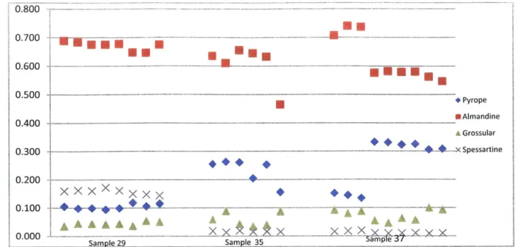
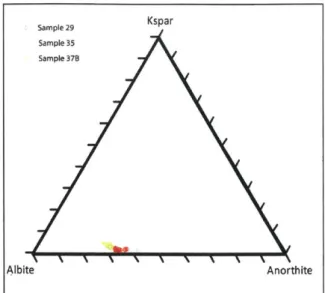
contact than far from the contact. Approximately half of the garnets are eroded and have reaction rims. The garnets also have numerous inclusions usually of quartz or biotite. The garnet has a consistent composition throughout the sample, indicating major garnet growth only once. The main composition is 70% almandine (Fig 12). The plagioclase also has a consistent composition throughout the sample of 65% albite and 35% anorthite (Fig 14).
Approximately 50 meters from the contact between the ultramafic massif and the gneiss is sample 35 which is gneiss (Fig 15). It has garnet + biotite + potassium feldspar + plagioclase+ muscovite + quartz + ilmenite + rutile + chlorite+ spinel kyanite sillimanite. The majority of the mica within the sample was chlorite which had altered from garnet, and the muscovite and biotite where small and
Figure 12 Garnet compositions, different sets of points are different grains
scarce. The sillimanite is not very abundant and seems to have been the result of kyanite which later changed phase into sillimanite. There seems to be two populations of the garnet one which is very large
up to 1 centimeter in diameter which has been dissolved at the edges. Around the larger garnets it is very common to have symplectite reaction rims previously described. The smaller garnets are much
more euhedral than the larger garnets. In addition the larger garnets also have many inclusions mainly of quartz, rutile, and sometimes biotite.
The two different populations are visible in the mineral compositions of the garnet within sample 35. Only one of the garnets analyzed is different but that is because the larger garnets were
more likely to have biotite near them and were therefore preferentially analyzed since biotite and garnet were needed for thermometry. The majority of the garnets analyzed which were the larger
garnets have a composition approximately 65% almandine, while the other garnet has a composition of
only 45% almandine. The plagioclase like the previous sample has a fairly uniform composition of 65%
albite and 35% anorthite.
0.800 0.700 0.600 0.500 0.400 0.300 0.200 0.100 0.000
U.
S*+Pyrope
- Almandine A Grossular 0.300** *
*. Spessartine
0.100qW1
T
L
A
A
A
AA
XAAAAAA X fX XX XA XX\
rt -4. 1434 gt BE 358Figure 14 Pictures from sample 35 taken using electron microprobe, new minerals identified: rt-rutile, il- ilminite, gt- garnet, ms- muscovite
I.
Sample 29 Kspar
Sample 35 Sample 37B
Albite Anorthite
Figure 13 Plagioclase ternary diagram showing composition
The next sample is number 36 which is a leucocratic zone from within 50 meters of the contact (Fig 16). This sample, since it was crystallized from a melted area from within the gneiss is fairly uniform and does not show many of the retrograde reactions that the samples in the surrounding gneiss show. The
main minerals are quartz + biotite + muscovite
+ potassium feldspar + sillimanite + plagioclase
+ kyanite. The minerals are fairly euhedral and appear in equilibrium except for some of the plagioclase. The plagioclase illustrates perthite structure with its exsolution lamellae and some of them are not in equilibrium with the
BE 36A BE 548
Figure 15 Sample 36
Figure 16 Sample 37
surrounding minerals.
The final sample which was studied in depth was sample 37 which is a gneiss from within 10
meters of the contact with the ultramafic massif (Fig 17). The minerals are garnet
+monzonite
+rutile
+ilmenite
+zircon
+quartz
+plagioclase
+potassium feldspar
+kyanite. This sample had many large
garnets like the previous samples, and still had many inclusions of quartz and other minerals. Garnet is
surrounded by a rim which is interpreted as a secondary reequilibration during retrogression as
previously described. There were also smaller garnets as well.
The mineral composition reflects the two populations of garnet. One population has
approximately 75% almandine, while the other population has approximately 55% almandine. The two
different compositions might indicate two different times of garnet growth. The larger garnets with
reaction rims are the garnets with the higher almandine content. The previous sample had the older
larger garnets with a greater almandine content, which is probably the same for this sample since they
are so close. Unlike the garnet the plagioclase has a relatively homogenous population that is consistent
with the plagioclase in all of the other samples. The plagioclase has a composition of approximately 65%
albite and 35% anorthite.
4.0000 3.5000 3.0000 2.5000 2.0000 1.5000 1.0000 0.5000 AN AA A A
KA
_ _ _ __.... A -*29 *35 A 37 0.0000 1- ---0.0000 1.0000 2.0000 3.0000 4.0000 5.0000 6.0000 7.0000 8.0000 9.0000 wt% MnO Figure 17 Graph showing variation with respect to Mno and CaOIn addition to the overall mineral composition variation within the garnets, specific to each sample there is also a distinction made between samples (Fig 18). When CaO and MnO are compared, the differences between the different populations of garnet becomes apparent. Sample 29 has a very different composition than sample 35 and sample 37. In addition it is also clear by this comparison that there are two populations within sample 37, although the difference between the two is not as great as
between sample 29 and the other samples. Sample 35 also most likely has two compositions, although the separation is not as apparent
The variation along the profile of the petrology of the samples is to be expected due to the
varying structures present and the distance from a major tectonic contact. Overall the samples further away from the contact have less reaction rims and are more in equilibrium than the samples closer to
samples closer to the contact which is not present further away. The analyses were used to get pressure and temperature estimates along the contact to look at the variation caused by the ultramafic body's emplacement within the gneiss.
Discussion
The structures studied along the profile as well as the petrology of the samples provide data for further study. The structures allow for a better understanding of the regional geology as well as large structures present in the massif and surrounding units. With the petrologic data collected from the samples along the profile pressure and temperature estimates were calculated that show trends in
pressure and temperature along the profile
Regional Structure
As previously discussed the overall structure of the Beni Bousera massif is an anticline (Reuber et al., 1982) (Kornprobst et al., 1995). The foliation of the surrounding gneiss, however, does not have a foliation corresponding to the foliation of the peridotite. Structurally, the gneiss is above the peridotite, and was deformed with it in an antiform (Fig 19). This happened when the Beni Bousera ultramafic
NNW
SSE
Figure 18 Schematic cross section through the massif and surrounding gneiss. The green is the peridotite, bright pink is Kinzingite, pale pink is gneiss, and the lines are the foliation of the different units. Pale section is eroded and no longer visible.
complex was brought to the upper crust from its previous emplacement in the lower crust on a thrust nappe during the Alpine Orogeny 20 Ma, as is commonly accepted (Chalouan and Michard, 2004). The overall anticline which bends both the peridotite and the gneiss with its preexisting foliation and structures is a result of the final thrust nappe which brought both the gneiss and peridotite to the
surface.
K
Figure 19 Structure of gneiss before it was folded, indicates direction of movement
The preexisting structures within the gneiss were partially obscured by the domed structure which overprinted the foliation. By restoring the contact between the peridotite and the gneiss to horizontal the foliation becomes clearer. As can be inferred due to the foliation which shallows in the gneiss along the profile, the
peridotite has moved up relative to the gneiss (Fig 20). This created a foliation which is the result of gneiss being dragged by the movement between the two units. This is to be expected as the peridotite had to come in contact with the gneiss by any of the mechanisms of emplacement of the massif.
Pressure and Temperature Estimates
Pressure and temperature estimates were made for a sample approximately 2 kilometers from the contact and a sample within 50 meters of the contact. In addition, a pressure estimate was made for a sample within 10 meters of the contact. A program by Frank Spear was used to do the calculations using the calibration of Hodges and Spear 1982 (Hodges and Spear, 1982), which was calibrated using metapelite schist. Garnet- biotite thermometry and garnet-plagioclase-aluminosilicate-quartz barometry was used.
The first sample yielded fairly Sample 29
10
consistent pressures and temperatures
8
with a temperature of 878 30 OC and a
6
pressure of 6.4 + .4 kbar. This temperature .0
- 4 7
is fairly hot and is within the range that the 6
2
metapelite gneiss would begin to melt, 4
which there is evidence for by the 0400 500 600 700 800 900
leucocratic zones (Fig 21). This sample did
Figure 20 Pressure and temperature estimates for
not have garnet and biotite touching which sample 29
could have impacted the results. This may be the reason why the sample gives such consistent data. The garnet and biotite may only exhibit the temperature that the sample was last in equilibrium, and does not record the retrograde metamorphism that another sample records.
Sample number 35 illustrates many different pressure and temperatures. This sample had biotite touching the garnet so Fe-Mg exchange was probably able to occur throughout the retrograde
reactions. The temperature is as high as 8001C
Sample 35
and a pressure as high as 8.5 kbar. Although the10
8 sample is within 2 kilometers of the previous
6 sample, the pressure is much higher than would
-0
be expected for moving 2 kilometers vertically within the crust. As shown by Fig 22, there are two main pressures and temperatures. The
40 500 600 700 800 900
T
0~ calculations disregard the highest, and twoFigure 21 Pressure and temperature estimates for
lowest temperatures and then are separated
sample 35
these distinctions group 1' s (the higher
Sample 37
pressure group) pressure is 8.06 .25 kbar 10
and temperature is 663 47 0C. 8
The final pressure is above 10 kbar 6
for sample 37 (fig 23). A temperature was
not able to be calculated since there was no 2
biotite within the sample, and no other 400 500 600 700 800 900
adequate combination of minerals for T0C
thermometry. This indicates a depth that is Figure 22 Pressure and temperature estimates for
well within the lower crust and could sample 37
potentially be very near the mantle. Using a temperature of 900 OC (slightly higher than sample 29) the
pressure calculated is 10.8 1.3 kbar.
There have been some previous pressure and temperature estimates that have been done on the gneiss surrounding the peridotite. Michard et al. in 1997 calculated the pressures and temperatures of the Filali schist, gneiss, Kinzingite and other units away from the massif. The gneiss had an average
pressure of 10-13 kbar and temperature of 800-8500C varying north to south within the unit, with the
lower pressures and temperatures being in the north. Within the Kinzingite in one location, the
maximum temperature and pressure they found was 16 kbar and 760-8200C. This however was not
found throughout all of the Kinzingite and was just a localized area(Michard et al., 1997). Kornprobst and Vielzeuf in 1984 gave pressure temperature estimates for the gneiss and Kinzingite as well. The
gneiss was between 5-8 kbar and 750-8000C. The Kinzingite was 10kbar and 7500C (Kornprobst and
Vielzeuff, 1984).
Both of the estimates provided by previous studies are consistent with the data gathered along this profile. The major difference is that Michard et al. found a very localized high pressure region. The
main difference between the data collected along this profile and the other data collected is that this data was done along a cross section as opposed to dispersed sampling. Data collection along the profile allowed for a more detailed illustration of the drastic pressure change along a small distance.
Emplacement of Beni Bousera
The emplacement of the massif, and other related massifs, has been debated (Chalouan and Michard, 2004). Based on structural and petrologic information gathered in this study along the detailed profile through the gneiss, it is still not clear which model best explains the massif's presence.
The majority of the structures along the profile were hot and ductile. The brittle structures present only over printed pre-existing ductile structures. The overall trend of the foliation is indicative of the massif moving up relative to the gneiss, and since this created a foliation instead of a series of faults, it was probably within the ductile region deep within the crust. Since within the Reuber model, the top fault is a thrust fault, it can be concluded that massif was not intruded as a mantle lens {Reuber, 1982 #18}. If it had been a fault the majority of the structures probably would have been brittle not ductile, therefore the Platt model seems to be less likely due to the lack of brittle structures that would be expected by a series of faults (Platt, 2007). Both the Platt model as well as the diapiric model (Loomis,
1972) would have an extensive shear zone around the ultramafic massif, although it is less likely with the Platt model. The ductile deformation also increases towards the contact. This would require heating which could be accommodated by the diapir model (Loomis, 1972), or from being deep within the crust with the Platt model {Platt, 2007 #26}. The lens model does have less heating associated with it, but it could be sufficient for the deformation found in Beni Bousera. There is also heating associated with the shearing of emplacement in that model as well. Overall, due to the hot ductile structures including the foliation, and the absence of significant brittle structures, it seems more likely that the massif was emplaced as a hot diapir or deep fault with original normal offset.
In addition to the structural data, the petrologic data also supports the theory of a diapiric or fault models emplacement of the peridotite. The increase in pressure along the profile is more than would be expected due to the change in overburden pressure that would occur by moving 2 kilometers vertically within the lower crust. A possible explanation for this unexpected change in pressure could be that the layers of gneiss surrounding the massif were sheared by the emplacement of a diapir. The shearing thinned the layers, which allowed areas of gneiss to be much closer together than the originally were in the lower crust. In order to accommodate the pressure difference found within the profile the crust represented by t the gneiss must have been thinned extensively. A pressure difference of 5 kbar as was found along the profile, usually represents a distance of 15 kilometers within the crust, assuming an
average density of 3000 kg/M3
. Instead of 15 kilometers, there was only a 2 kilometer difference
between the sample yielding 5 kbar and the sample yielding 10 kbar. The thinning would be the result of extensive shear. This shear would most likely be created through the the diapir model (Loomis, 1972) (Reuber et al., 1982). This could also occur through the Platt model, if there was significant thining through neighboring normal faults surrounding the peridotite within the lower crust {Platt, 2007 #26}. Although the results are not conclusive both the petrologic data and the structural data seems to indicate that extensive shear and ductile behavior was necessary for the emplacement of the massif. Although the mechanism of emplacement is not totally understood, it is more likely either a diapir (Loomis, 1972) or a of a series of faults (Platt, 2007).
The structures and petrology observed in Beni Bousera in order to infer the contact relationship are similar to those observed within the Ronda massif. The Ronda Massif in southern Spain is related to the Beni Bousera ultramafic complex both in emplacement and overall tectonic setting. The Ronda massif has been studied much more than the Beni Bousera massif. Therefore, it is beneficial to compare Ronda and Beni Bousera in order to gain knowledge about potential mechanisms of emplacement. Due to the nature of the contact and other evidence the Ronda massif has traditionally been interpreted as a
hot asthenosphere diapir (Loomis, 1972). But recently this interpretation has been changing due to new models that account for the gravity anomalies and other factors with a different explanation than the diapir, like a complicated thrust nappe structure (Platt et al., 2003a). It is unclear which model is correct, and the type of emplacement of Ronda is important because it is probably the same mechanism for Beni
Bousera.
The northern and western edges of the Ronda massif are the most well exposed contact sections. In Ronda, like in Beni Bousera there is a contact between peridotite and gneiss. The gneiss is from a pelitic Paleozoic sequence and Mesozoic carbonate sequence. The peridotite, approaching the contact from inside the massif, has increasing pyroxenite dikes towards the edge. In the gneiss
approaching the contact the dip of the foliation increases, and the rocks have undergone a higher extent of metamorphism closer to the contact(Loomis, 1972). This is similar to what happens in the Beni
Bousera massif except, within the profile studied the foliation was overturned due to an anticline which reversed the dip of the foliation. Around the edge there are steeply dipping normal faults, and the gneiss that is in contact with the peridotite is from deeper structural level in the section than the other rocks. This presense of a vertical contact indicates that the peridotite was intruded into the overlying gneiss as a hot diapir. After the intrusion the massif is thought to have undergone little other
deformation except that post intrusional high angle faulting occurred along the margin of the massif and re-activated older faults in the opposite direction (Loomis, 1972). The relationships in Ronda that are observed with the faults that are reactivated in the opposite direction are also observed within the gneiss around Beni Bousera. The lineation for the ductile structures was directly opposite that of the brittle structures which is indicative of the reactivating of preexisting structures.
In addition to structural information there is also a large gravity anomaly in the Ronda massif, the peridotite. The peridotite body is surrounded by a layer of serpentinite, like in Beni Bousera, which in Ronda is classified as a shear zone between the gneiss and the peridotite due to hot temperature of
emplacement (Loomis, 1972). The change in deformation approaching the contact is also present in Beni Bousera. The presence of the gravity anomaly is complicated and has not adequately been explained. Some say that the gravity anomaly indicates that Ronda is a diapir with steep sides
descending deep, causing the abrupt gravity anomaly (Loomis, 1972). The gravity anomaly can also be explained as a piece of detached slab sitting below the massif. The alternate view to the diapiric model suggests that there is a complicated lithospheric structure. The lithosphere is thin, less than 60 km, and below the thin lithosphere is an aseismic low-velocity asthenosphere. Due to the complicated
subduction history in the region of southern Spain and northern Morocco with proposed two subduction zones, part of one of the down going slabs is still beneath the massif creating a gravity anomaly because it has detached or delaminated. It is also proposed that the Miocene deformation was not sufficient for a diapir to occur and basement gneiss to be brought up. The massif is interpreted to be a result of a complex nappe structure from multiple deformational events similar to the proposal that Beni Bousera was result of thrusting in the Jurassic, and then in the Miocene (Platt et al., 2003b).
The Ronda contact, although it is not completely understood, is more likely to be the result of a hot diapir, although the series of nappes complicates the gravity anomaly existing in the massif. The similarities between metamorphic grade, variation approaching contact in the peridotite, and other factors, makes it likely that Beni Bousera is also the result of a more ductile structure. Although the two
massifs are not attached they are associated enough and in the same tectonic setting that emplacement for Ronda and Beni Bousera can be inferred to be related.
Conclusion
The Beni Bousera ultramafic complex in northern Morocco has a complex relationship with its surrounding units. The gneiss surrounding the massif generally exhibits ductile structure, with occasional brittle structures which locally overprint the preexisting brittle structures. The gneiss has increasing
and temperature in the gneiss increase towards the contact, with the pressure increases dramatically more than would be expected by moving the same distance vertically with in the lower crust. The contact itself is obscure. Where visible the peridotite is highly serpentinized and altered and the gneiss side appears to be very ductile. The study of the gneiss provides information on the emplacement of the Beni Bousera massif as well as other orogenic lherzolites in the western Mediterranean.
Future Research
In order to continue to learn about the massif and gneiss future research would be beneficial. Specifically it would be helpful to date gneiss in various locations along the profile. If samples were dated from far away from the contact up to the contact a rate of emplacement could be inferred which would help constrain the mechanism of emplacement. In addition, further sample collection and pressure temperature estimates would be helpful in order to get more data that is better confined. Profiles through the garnet would also be useful to see if there is significant evidence of heating events within the garnets. Overall more data collection would increase the understanding of the contact relationship in the massif.
References
Chalouan, A., and Michard, A., 2004, The Alpine Rif Belt (Morocco): a case of mountain building in a subduction-subduction-transform fault tirple junction: Pure and Applied Geophysics, v. 161, p. 489-519.
Hodges, K.V., and Spear, F.S., 1982, Geothermometry, geobarometry and the AI2SiO5 triple point at Mt. Moosilauke, New Hampshire: American Mineralogist, v. 67, p. 1118-1134.
Kornprobst, J., Tabit, A., Targuisti, K., Draoui, M., and Woodland, A.B., 1995, A trip to Beni Bousera Ultramafic Massif (Morocco): Field guide to the post conference field trip of the 2nd workshop on orogenic lherzolites.
Kornprobst, J., and Vielzeuff, D., 1984, Transcurrent crustal thinning: a mechanism for the uplift of deep continental crust/upper mantle associations: Developments in Petrology Series, v. 11B, p. 347-359.
Loomis, T.P., 1972, Diapiric emplacement of the Ronda high-temperature ultramafic intrusion, Southern Spain: Geological Society of America Bulletin, v. 83, p. 2475-2496.
-, 1975, Tertiary Mantle Diapirism, Orogeny, and Plate Tectonics East of the Strait of Gibraltar:
American Journal of Science, v. 275, p. 1-30.
Michard, A., Chalouan, A., Feinberg, H., Goffe, B., and Montigny, R., 2002, How does the ALpine belt end between Spain and Morocco?: Geologic Society of France Bulletin, v. 173, p. 3-15.
Michard, A., Goffe, B., Bouybaouene, M.L., and Saddiqi, 0., 1997, Late Hercynian-Mesozoic thinning in the Alboran domain: metamorphic data from the northern Rif, Morocco: Terra Nova, v. 9, p. 171-174.
Michard, A., Saddiqi, 0., and Chalouan, A., 2008, Continental Evolutoin: The Geology of Morocco: Berlin, Springer.
Montel, J.M., Kornprobst, J., and Vielzeuff, D., 2000, Preservation of old U-Th-Pb ages in shilded monazite: example from the Beni Bousera Hercynian kinzingites (Morocco): Journal of Metamorphic Geology, v. 18, p. 335-342.
Pearson, D.G., Davies, G.R., Nixon, P.H., and Milledge, H.J., 1989, Graphitized diamonds from a
peridotite massif in Morocco and implications for anomalous diamond occurrences: Nature, v. 338.
Platt, J.P., 2007, From orogenic hinterlands to Mediterranean-style back-arc basins: a comparative analysis: Journal of the Geological Society, London, v. 164, p. 297-311.
Platt, J.P., Allerton, S., Kirker, A., Mandeville, C., Mayfield, A., Platzman, E.S., and Rimi, A., 2003a, The ultimate arc: Differential displacement, oroclinal bending, and vertical axis rotation in the External Betic-Rif arc: Tectonics, v. 22.
Platt, J.P., Argles, T.W., Carter, A., Kelly, S.P., Whitehouse, M.J., and Lonergan, L., 2003b, Exhumation of the Ronda peridotite and its crustal envelope: constraints from thermal modelling of a P-T-time array: Journal of the Geological Society, London, v. 160, p. 655-676.
Reuber, I., Michard, A., Chalouan, A., Juteau, T., and Jermoumi, B., 1982, Structure and emplacement of the alpine-type peridotites from Beni Bousera, Rif, Morocco: a polyphase tectonic
interpretation: Teconophysics, v. 82, p. 231-251.
Slodkevich, V.V., 1983, Graphite paramorphs after diamond: International Geology Review, v. 25, p. 497-514.
Zeck, H.P., 1996, Mantle peridotites outlining the Gibraltar Arc- centrifugal extensional allochthons derived from th eearlier Alpine, westward subducted nappe pile: Teconophysics, v. 281, p. 195-207.
Appendix
Table 1: Weight percent analyses
Sample 29 29 29 29 29 29 29 29 29 29 29 29 29 29 29 29 29 29 29 29 29 29 29 29 29 35 35 35 35 35 35 Mineral Garnet Garnet Garnet Garnet Garnet Garnet Garnet Garnet Biotite Biotite Biotite Biotite Biotite Biotite Biotite Biotite Plag Plag Plag Plag Plag Plag Plag Plag Plag Garnet Garnet Garnet Garnet Garnet Garnet Biotite Biotite Biotite Biotite Biotite Biotite Sio2 37.0800 37.3900 37.3500 37.0500 37.4500 37.6800 37.6100 37.0000 34.7700 34.5800 35.0300 35.4300 35.2000 34.8400 35.0600 34.8200 62.0600 61.0800 62.1900 61.9100 62.2600 61.8000 61.1500 61.0500 61.0000 38.0600 38.2175 38.3800 37.5540 38.0440 37.5250 35.4200 38.4025 37.3238 36.5725 36.8230 41.4733 Tio2 Cr2o3 0.0000 0.0000 0.0000 0.0078 0.0000 0.0296 0.0000 0.0112 0.0000 0.0175 0.0000 0.0148 0.0000 0.0413 0.0000 0.0151 3.2600 0.0000 3.1700 0.0000 3.2500 0.0000 3.0900 0.0000 3.0000 0.0000 2.8587 0.0000 2.5282 0.0000 2.3070 0.0000 0.0000 0.0000 0.0000 0.0000 0.0000 0.0000 0.0000 0.0000 0.0000 0.0000 0.0000 0.0000 0.0000 0.0000 0.0000 0.0000 0.0000 0.0000 0.4411 0.0781 0.0557 0.0267 0.0606 0.0346 0.0798 0.0576 0.0697 0.0505 0.1182 0.0789 6.5233 0.0489 5.5794 0.0054 5.4594 0.0357 4.5200 0.0174 5.0030 0.0437 5.8633 0.1058 0.0000 0.0000 0.0000 0.0000 0.0000 0.0000 0.0000 0.0000 0.0000 0.0000 0.0000 0.0000 0.0000 0.0000 0.0000 0.0000 Al2o3 21.7000 21.9400 21.9900 21.9200 21.9200 21.7900 21.9100 21.7800 20.0500 19.7900 20.3200 20.5300 20.3600 20.3300 20.3100 20.1000 25.0100 25.9000 25.4700 25.3900 26.0500 25.6600 25.7000 26.0600 25.8600 22.1300 22.2025 22.4160 21.9140 22.2160 21.9125 17.2867 15.4881 17.2306 16.0825 17.1175 13.6033 Feo 30.7600 30.8600 30.3500 30.5500 30.5100 29.6000 29.5000 30.3600 20.5700 20.5200 20.6200 21.8800 21.4900 21.5600 21.6800 21.5100 0.0793 0.0528 0.0601 0.0000 0.0000 0.0128 0.0060 0.0064 0.0134 29.7167 28.4600 30.3980 32.5500 30.4920 29.3550 15.2200 13.0756 13.4944 14.4650 14.1710 15.5400 0.3595 0.2075 0.061 0.2163 0.3613 0.3392 0.1971 0.4719 0.0092 14.2075 0.0515 13.4825 0.0290 10.8167 0.0000 0.0000 0.0000 0.0000 0.0000 0.0000 0.0000 0.0000 0.0267 0.022 0.0282 0.0127 0.0152 0.0408 0.0157 0.0129 Mno 7.0300 7.2200 7.0900 7.6400 7.1600 6.7600 6.6600 6.3700 0.4648 0.4553 0.5184 0.4513 0.4988 0.5083 0.4673 0.4640 0.0000 0.0000 0.0000 0.0000 0.0000 0.0000 0.0000 0.0000 0.0000 0.8627 0.6228 0.9066 0.7456 0.7603 0.8311 0.0580 0.0173 0.0137. 8.58 7.42 7.3 7.29 7.63 7.17 7.19 6.94 Mgo 2.6284 2.4807 2.4940 2.3770 2.4966 3.0400 2.7067 2.9017 6.8800 6.9900 7.0900 6.8000 6.7900 6.9600 7.3000 7.4500 0.0049 0.0000 0.0000 0.0000 0.0000 0.0047 0.0000 0.0086 0.0000 6.6833 6.8425 6.7780 5.5360 6.6920 4.7600 12.2533 14.4069 13.6644 Cao 1.2348 1.5808 1.5414 1.4803 1.5410 1.3067 1.9442 1.7676 0.0449 0.0296 0.0324 0.0119 0.0397 0.0447 0.0384 0.0405 6.6100 7.5000 6.9800 6.7000 7.0900 6.5000 7.0500 7.5300 7.3400 2.1693 3.1850 1.5722 1.2921 1.4678 3.6925 0.1583 0.0615 0.0000 0.0846 0.0806 0.1032 35 35 35 35 35 35 35 35 35 35 35 35 35 35 27.37 26.06 26.19 26.04 26.46 26 26.04 25.94 Plag Plag Plag Plag Plag Plag Plag Plag Na2o K2o 0.0000 0.0000 0.0009 0.0000 0.0000 0.0000 0.0000 0.0000 0.0000 0.0000 0.1562 0.0000 0.0000 0.0000 0.0162 0.0000 0.0704 9.1300 0.0788 8.9400 0.1144 9.2400 0.0975 9.0400 0.1165 9.2000 0.0820 9.1100 0.1222 9.1600 0.0819 9.0200 7.6600 0.3674 7.3000 0.2810 7.9500 0.2035 7.7300 0.2896 7.6000 0.2377 7.4600 0.2741 7.8000 0.2868 7.0900 0.3122 7.6900 0.2097 0.0450 0.0000 0.1126 0.0000 0.0215 0.0000 0.3402 0.0000 0.2382 0.0000 1.1984 0.0000 0.5277 8.2033 0.5610 7.9350 0.2173 8.8063 0.3951 8.4550 0.3397 8.3595 0.7541 8.2167 6.5 0.2364 7.25 0.1377 7.08 0.2795 7.33 0.2518 7.17 0.2029 7.57 0.2 7.44 0.2226 7.02 1.0503 58.07 59.93 59.64 60.04 59.32 59.85 60.13 59.45 Total 100.4200 101.4900 100.8400 101.0200 101.1000 100.3500 100.3700 100.2200 95.2400 94.5500 96.2100 97.3200 96.7100 96.2900 96.6700 95.8000 101.7900 102.1100 102.8600 102.0200 103.2400 101.7000 101.9900 102.0600 102.1200 100.1933 99.7225 100.5680 100.0700 100.0320 99.4725 95.7033 95.5338 96.2488 94.8100 95.4765 96.5033 101.14 101.02 100.58 101.19 101.17 101.17 101.24 100.89