HAL Id: hal-01303867
https://hal.sorbonne-universite.fr/hal-01303867
Submitted on 18 Apr 2016
HAL is a multi-disciplinary open access
archive for the deposit and dissemination of
sci-entific research documents, whether they are
pub-lished or not. The documents may come from
teaching and research institutions in France or
abroad, or from public or private research centers.
L’archive ouverte pluridisciplinaire HAL, est
destinée au dépôt et à la diffusion de documents
scientifiques de niveau recherche, publiés ou non,
émanant des établissements d’enseignement et de
recherche français ou étrangers, des laboratoires
publics ou privés.
Distributed under a Creative Commons Attribution| 4.0 International License
Buffered high charge spectrally-peaked proton beams in
the relativistic-transparency regime
N.P. Dover, C.A.J. Palmer, M. J.V. Streeter, H. Ahmed, Bruno Albertazzi, M.
Borghesi, D.C. Carroll, J. Fuchs, R. Heathcote, P. Hilz, et al.
To cite this version:
N.P. Dover, C.A.J. Palmer, M. J.V. Streeter, H. Ahmed, Bruno Albertazzi, et al.. Buffered high charge
spectrally-peaked proton beams in the relativistic-transparency regime. New Journal of Physics,
Institute of Physics: Open Access Journals, 2016, 18, pp.013038. �10.1088/1367-2630/18/1/013038�.
�hal-01303867�
This content has been downloaded from IOPscience. Please scroll down to see the full text.
Download details:
IP Address: 134.157.80.213
This content was downloaded on 18/04/2016 at 15:37
Please note that terms and conditions apply.
Buffered high charge spectrally-peaked proton beams in the relativistic-transparency regime
View the table of contents for this issue, or go to the journal homepage for more 2016 New J. Phys. 18 013038
(http://iopscience.iop.org/1367-2630/18/1/013038)
New J. Phys. 18 (2016) 013038 doi:10.1088/1367-2630/18/1/013038
PAPER
Buffered high charge spectrally-peaked proton beams in the
relativistic-transparency regime
N P Dover1 , C A J Palmer1 , M J V Streeter1 , H Ahmed2 , B Albertazzi3 , M Borghesi2 , D C Carroll4,5 , J Fuchs3 , R Heathcote5 , P Hilz6,7 , K F Kakolee2,8 , S Kar2 , R Kodama9 , A Kon9 , D A MacLellan4 , P McKenna4 , S R Nagel1 , D Neely4,5, M M Notley5, M Nakatsutsumi3,10, R Prasad2,11, G Scott4,5, M Tampo9, M Zepf2, J Schreiber6,7andZ Najmudin1
1 The John Adams Institute for Accelerator Science, Blackett Laboratory, Imperial College, London SW7 2BZ, UK 2 Centre for Plasma Physics, Queen’s University Belfast BT7 1NN, UK
3 LULI, École Polytechnique, CNRS, CEA, Palaiseau, France
4 SUPA Department of Physics, University of Strathclyde, Glasgow G4 0NG, UK
5 Central Laser Facility, STFC Rutherford Appleton Laboratory, Oxfordshire OX11 0QX, UK
6 Fakultät für Physik, Ludwig-Maximilians-Universität München, Am Coulombwall 1, D-85748 Garching, Germany 7 Max-Planck-Institut für Quantenoptik, Hans-Kopfermann-Str. 1, D-85748 Garching, Germany
8 Jagannath University, Dhaka, Bangladesh
9 Graduate School of Engineering, Osaka University, Osaka D-565-0871, Japan 10 European XFEL, GmbH, Albert-Einstein-Ring 19, 22671 Hamburg, Germany
11 Institute for Laser and Plasma Physics, Heinrich Heine University, Düsseldorf, D-40225, Germany E-mail:nicholas.dover08@imperial.ac.uk
Keywords: laser–plasma interaction, ion acceleration, laser ion source, proton acceleration Supplementary material for this article is availableonline
Abstract
Spectrally-peaked proton beams of high charge
(E
p»
8 MeV
,
D »
E
4 MeV
, N
»
50
nC
) have been
observed from the interaction of an intense laser
( 10
>
19W cm
−2) with ultrathin CH foils, as measured
by spectrally-resolved full beam profiles. These beams are reproducibly generated for foil thicknesses
5
–100 nm, and exhibit narrowing divergence with decreasing target thickness down to 8
» for 5 nm.
Simulations demonstrate that the narrow energy spread feature is a result of buffered acceleration of
protons. The radiation pressure at the front of the target results in asymmetric sheath
fields which
permeate throughout the target, causing preferential forward acceleration. Due to their higher
charge-to-mass ratio, the protons outrun a carbon plasma driven in the relativistic transparency regime.
1. Introduction
The interaction of high intensity lasers with opaque plasma has been widely investigated as a source of multi-MeV ions. Irradiation of micron thick foils at high laser intensity produces sheathfields that can accelerate protons[1,2]. However, these beams characteristically have a thermal spectrum. Limiting the energy spread of these beams, especially reducing low energy parasitic ions, is a key objective in thisfield. Schemes to reduce the energy spread of sheath accelerated beams often rely on spatially localising the protons within a mixed species foil. This was demonstrated by manufacturing targets with the required ion species localised on the target rear surface[3–5]. A similar effect can be achieved by pre-expanding the foil [6], so that protons can be separated from a trailing lower charge-to-mass ratio host ion species.
Simulations have shown species separation also occurs when a single high-intensity pulse interacts with multi-species thin(100nm) targets [7–9]. For target thickness comparable to the skin-depth, d0 g(c wp),
species separation rapidly occurs due to laserfield penetration into the target [8,9]. The target remains opaque during the interaction if d0drtº (gn nc e0)cs Lt, where ng is the relativistic critical density, nc e0is the initial
electron density, the expansion time is the laser pulse durationtL, and csis the target surface sound speed;
expansion towards the laser is suppressed by radiation pressure. The foil can then be accelerated by light sail radiation pressure acceleration(RPA) [12–17]. Spectrally peaked proton beams from 10 to 100 nm foils OPEN ACCESS
RECEIVED
11 June 2015
REVISED
3 December 2015
ACCEPTED FOR PUBLICATION
15 December 2015
PUBLISHED
18 January 2016
Original content from this work may be used under the terms of theCreative Commons Attribution 3.0 licence.
Any further distribution of this work must maintain attribution to the author(s) and the title of the work, journal citation and DOI.
accelerated in the light sail regime have been reported using high-Z foils witht ~ psL 1 [10] or carbon foils with 50
L
t ~ fs[11]. The proton layer is spatially separated from, and accelerated ahead of, the higher-Z species. RPA can be disrupted by the transverse instabilities that form at the laser–plasma interface [18], but due to the spatial separation from this unstable region the protons can be insulated from these instabilities, and can be considered to be‘buffered’ by the higher-Z species [9]. Although the plasma fields are strongly transversely modulated in the unstable region, the large angular divergence of locally accelerated electrons results in smoother accelerating space chargefields away from this region.
If the target becomes relativistically transparent during the laser–plasma interaction (d0drt), RPA is
suppressed, and an increase in the coupling of the laser energy to thermal electrons drives a rapid asymmetric expansion of the plasma[21]. Recent experiments have demonstrated enhanced acceleration from targets driven in this regime[19–23]. Removing protons prior to interaction with relativistically transparent targets resulted in higher carbon energies[24]. Simulations of multi-species targets in this regime also exhibit buffering of
protons[7].
We present thefirst experimental measurements of fully spatially characterised spectrally-peaked proton beams from any laser-solid target ion acceleration experiment. We use relatively long laser duration(t ~ psL 1 ) combined with nanometre-thickness carbon foils to thermally drive the acceleration, in contrast to previous experiments showing spectrally modulated beams from RPA[10,11]. The narrow energy spread proton beams were observed for thefirst time from a thermally driven foil without the need for target microstructures or deliberate pre-expansion. The high charge( 50» nC) beams had typical peak energy Ep»8MeV,
corresponding to the velocity of the carbon ion front, andD »E 4 MeV. Spatial profile measurements also revealed a novel plasma lensing effect in which the beam divergence reduced with decreasing target thickness d0
to» 8 for 5 nm foils. Numerical simulations, consistent with the experiment, demonstrate that the target becomes relativistically transparent to the laser. The majority of the ion energy gain occurs in this phase, not from RPA. The protons are spatially separated from and buffered ahead of the heavier carbon ions while being protected from transverse instabilities dominating the carbon species. This generation of highly collimated, high charge, narrow energy spread beams devoid of a low-energy parasitic component is ideal for numerous
applications, such as radioisotope generation or injection into accelerators.
2. Experimental results
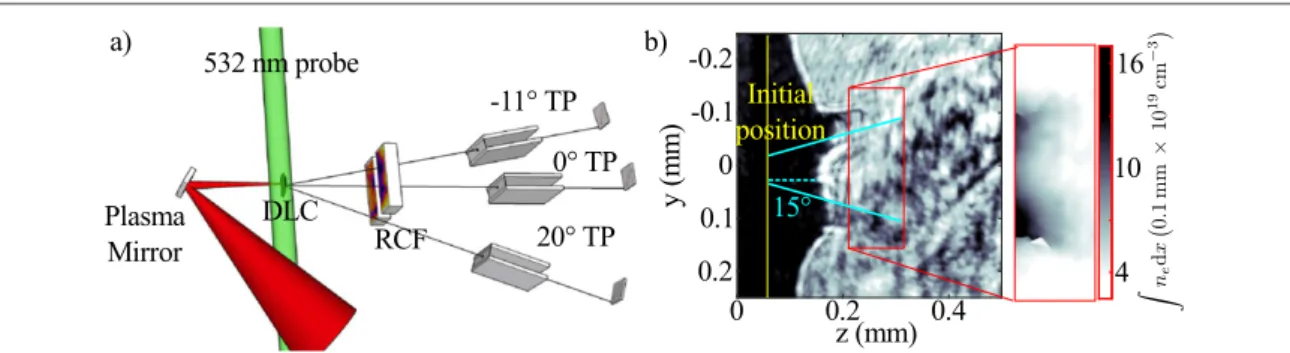
The experiment was performed using Vulcan Petawatt(l =1.054μm) at the Rutherford Appleton Laboratory. The experimental set-up is shown infigure1(a). A plasma mirror irradiated at 3´1014W cm−2enhanced the
laser contrast to»10-10[25]. The resulting (130 ± 20) J, L
t » 700 fs pulse was f 3 focussed with 35% of the
energy within a focal spot(1/e2) width w0= μm, measured at low power. The implied full power intensity is8 therefore IL» ´1 1020W cm−2, assuming no difference at focus between low and high power. The laser was either linearly polarised(LP) in the vertical direction or, by inserting a zero-orderl 4waveplate(92%energy transmission) in the focussing beam before the plasma mirror, circularly (CP) polarised. The transmission of s-and p- polarisation through the plasma mirror was measured to be 68% s-and 72% respectively, s-and thel 4 waveplate optical axis was rotated to account for this. The laser was normally incident onto diamond-like carbon (DLC) foils of thicknessd0Î5–500 nm, which were rear mounted on a circular aperture of 1 mm diameter. The
foils had a densityr »2.8g cm−3and comprised of an estimated» % C/10% H in the bulk (from elastic90 recoil detection analysis) [26]. They also form an additional nanometre-scale hydrocarbon impurity layer before laser irradiation.
Figure 1.(a) Experimental set-up. (b) Probe shadowgraphy at t=250 ps after the interaction together with phase map, in units of the line density integral, from simultaneous interferometry(red box) for d0=100 nm, LP. The yellow line indicates the initial position of the rear surface measured before the shot.
2
The proton beam profile was diagnosed using a radiochromic film (RCF) stack, allowing observation within 30
full-angle. The dose deposited in each layer of the stack is dominated by a small range of proton energies, E, which have their Bragg peak in the sensitive layer in the RCF. There is a further lesser contribution from higher energy particles which deposit a small fraction of their energy as they slow down in the layer[27]. Carbon ions would require>80 MeVto reach the RCF. Only small numbers of C ions were measured at these high energies and carbon was therefore assumed to contribute negligible dose to the RCF stack. High-resolution spectra were recorded using three Thomson parabola(TP) spectrometers. The TP sampled 0°, −11°and +20° behind a horizontal gap in the stack(figure2). TP use co-linear magnetic and electric fields to separate and disperse ions by charge-to-mass ratio and energy, with the resultant signal measured using imaging plate detectors[29]. The combination of these diagnostics allows combined spatial and high resolution spectral measurement of the proton beam.
Additionally an optical probe beam(l =532nm) passed transversely across the target rear surface with an adjustable time delay with respect to the intense pulse before being split into shadowgraphy and Mach–Zender interferometry. An example shadowgraphy image taken 250 ps after the irradiation of a 100 nm target with LP is shown infigure1(b). A clear cone like structure is seen on the shadowgraphy, and processed interferometry shows a significant reduction of the electron density along the laser-axis. Such a plasma distribution was typical of all the foils in this thickness range. We note that this differs from previous optical probing performed on thin foils driven by radiation pressure on Vulcan Petawatt, which show typically isotropic expansion from the focal region[28].
Examples of proton beam profiles are shown for CP and LP withd0=5–100 nm in figures2(a)–(d) (full
datasets are available in the supplemental data). For E=4 MeV, the beam is dominated by an annular ring with divergence angle> . This ring structure was characteristic for all polarisations and thicknesses. On occasion20 the ring structure was directed into the−11° TP revealing a high-flux(» ´5 10 MeV12 -1sr-1)broadband beam
Figure 2.(a)–(d) Proton beam profiles from d0= , 10, 20, 100 nm using CP, LP, CP, LP respectively at5 4, 9, 15 MeV. Red dot represents laser-axis, and black rings are at 10, 20° full-cone angle. The 0, −11° TP are indicated with black crosses. (20° TP is off the right edge). All films are contrast enhanced, and dark colour represents higher dose. Dose line outs from the dotted green lines for each target thickness are given in the bottom row. The E=15 MeV line out has been multiplied by 3.
3
with energy up to Emax»5 MeV. The emission angle of the annular ring is similar to the plasma expansion of the cone seen on the optical probe(figure1(b)).
For E=9 MeV, the annular ring has disappeared for all target thicknesses. Instead, a more collimated circular beam is seen near the laser-axis for d0100 nm, which is not always present for E=4 MeV. This beam has a full-angle divergence< , and becomes less divergent for thinner targets. For d20 020 nm, a halo surrounds the central beam with afilamented structure. The filamentation is not transposed onto the central beam. By E=15 MeV, the distinct central beam has disappeared in all but the thinnest targets, leaving a more divergent lowerflux beam. This is distinct from a lower flux beam with a very smooth transverse profile visible over a number of layers at the rear of the stack, which would correspond to proton energies significantly higher than observed on the TP. Hence since this feature cannot be protons, it is inferred to be due to electrons. This beam is shown in the supplemental data.
We note that the dose deposited in the RCFfilm in this region at E=9 MeV is comparable to the dose at E=4 MeV (figure2, bottom row), even though the dose in the 4 MeV film is additionally affected by protons with energies between 4 and 9 MeV. This indicates that the proton spectrum is highly non-thermal. As the RCF stack was not sufficiently resolved to adequately sample the energy spectrum, the TP data was used to give higher resolution spectral measurements. However due to the large spatial variations in the proton beam profiles, care must be taken to correlate the TP data with specific features from the RCF images.
Proton spectra from all three TPs for d0=20 nm(CP) are given in figure3(a), showing a pronounced peak with energy Ep=8 MeV, and energy spreadD »E 4 MeV, but only at0◦. Evidently this spectral peak corresponds to the central beam observed in the beam profiles in figure2(a)–(d). The peaked spectrum is also compared with on-axis spectra for d0=5, 20, 20, 100 nm(CP, CP, LP, LP) in figure3(b). Using the beam divergence from the 9 MeV profile, and integrating the spectrum gives 3( 1)´1011protons» nC within50
the spectral FWHM for d0=20 nm, with a conversion efficiency of laser energy 0.25%» . We note that spectrally peaked proton beams of similar energies were generated down to d0=5 nm. This suggests that the laser prepulse or rising edge does not destroy the target prior to the peak of the pulse, which would result in reduced efficiency for ion acceleration for the thinnest targets [22].
The corresponding carbon spectra are also plotted. They are thermal with a maximum velocity
vcf » ´3 10 ms7 -1corresponding to the start of the proton peak. The protons in the peak have outrun the C6+ front. This explains why the profiles for these central beams shown in figure2are free from instabilities
experienced by the carbon plasma, since the carbon front would act as a barrier to laser driven instabilities. On shots featuring the bright central beams, a highly divergent but comparatively lowflux proton beam was also measured on the TP, reaching energies(Emax»20–30 MeV). This is visible on the E»15 MeVprofiles in figure2, and was sufficiently divergent to be observed on the 20° TP, outside the ring.
The variation of the energy of the proton beam, Ep, and energy spread,DE, with d0is shown infigure4(a).
Both laser polarisations showed similar results for d0Î20 100 nm– , and for this range the data points represent the mean of both LP and CP. The graph is composite from 15 shots; the standard deviation of the repeat measurements is indicated by the vertical bars. Of these, 11 shots between 10 and 100 nm showed a clear central beam on the RCF combined with spectral peaks on the TP. A lack of sensitivity to polarisation has been observed previously for ultra-thin foils, and was attributed to target deformation negating the desired electron heating suppression for CP[10,30]. However for d0=5 nm, only CP resulted in spectrally peaked beams; LP produced a thermal spectrum with Emax»5 MeV, significantly lower than that for CP and shown as a separate data point. No peak was observed for d0=500 nm. Also plotted infigure4(a) are the maximum carbon and proton energy
Figure 3.(a)H+spectra from all TPs from CP, 20 nm target(figure2(c)) on a logarithmic scale. (b)H+(solid) and C6+ion(dashed)
spectra on 0° TP for different polarisations/thickness (in nm) with a linear ion number scale. The 5 nm (CP) corresponds to shot in figure2(a) and the 20 nm (CP) corresponds to figure2(c).
4
per nucleon,Emax, as observed on any TP, averaged over multiple shots. The maximum energy was most often
off-axis on the 20° TP, as has previously been reported from relativistically transparent targets [23].Emaxfor the C6+ions correlates well with E
p, confirming the velocities are linked.
Figure4(b) shows that the divergence of the central beam decreases with decreasing d0, as apparent in
figures2(a)–(d), down to» 8 for d0=5 nm. By contrast, the low energy ring divergence, measured at 4 MeV, remains at26 5 , again indicating that these are separate populations.
3. Numerical simulation and interpretation
To understand the mechanism by which these high charge narrow energy spread proton beams were produced, representative simulations were run with the 2D particle-in-cell(PIC) code OSIRIS [31] in a box of 160×80 μm with cell size 4´10 nm. The target was composed of 90/10% of C6+/H+by charge density with
ne=1000nc, and 2500 particles per cell per species. Resolution and particles per cell were optimised by
convergence scans, and care was taken to ensure the simulation box was large enough to not influence dynamics. The boundaries were absorbing for particles andfields. The initial density was set slightly higher than DLC (r »2.8g cc−1, ne»850nc) to account for the hydrocarbon impurity layer. Initial target thickness d0was
varied between 5 and 100 nm. The electron temperature was initialised at Te0=200 eVfor numerical reasons, resulting in target expansion before the arrival of the laser of approximately50 nm»2cs at, wheret is thea
simulation time before the pulse reaches the target. Although the effective initial target thickness is therefore larger than initialised, the areal density remains consistent with the experimental parameters. The initial target temperature relaxes the resolution constraints, and the effect of changing the initial temperature has been previously investigated[22]. The laser was initialised from an antenna located on the boundary with CP or LP and gaussian transverse and longitudinalfield profiles with w0=22μm,t =L 650fs, and a0ºeE mc0 w0= :3
IL»1019W cm−2. Although this exceeds the experimental focal spot size at low power, we note that the high power focal spot was not measured experimentally, and could vary significantly due to the differences in the laser phase front combined with the expansion of the plasma mirror over the»1ps pulse. We also note that 2D simulations are likely to underestimate target decompression therefore overestimating acceleratingfields in the expanding sheath, and may also affect plasma heating dynamics particularly for CP. However, 3D simulations of the interaction at sufficient resolution are prohibited by computational constraints. As will be shown, the focusing parameters provide the best match to the experimental results, and therefore likely give the best description of the plasma dynamics relevant to our experiment.
For d0=10 nm, early-on all the electrons in the focal spot are heated to the instantaneous ponderomotive potential and sheath formation is enhanced. The target expands during the rising edge of the laser from sheaths at both surfaces. As a result the longitudinalfield within the target passes through zero, and in this phase most protons remain within the target. This is different to the case where the target remains comparable in size to the initial skin depth as in RPA schemes, where species separation is almost instantaneous[8,9].
As the laser intensity increases, the radiation pressure, PR, of the pulse exceeds the plasma thermal pressure
Pt, or I tL( ) c >n t k T te( ) b e( ), and the front surface recedes. In this stage, the front surface is prone to transverse
instability[18], enhancing target decompression and quickly causing it to become transparent. The electron and Figure 4. As a function of d0:(a) maximum energy per nucleon forH+(filled red circles, with empty red circle for 5 nm LP) and C6+
(blue squares) and energy ofH+peak(green diamonds) with FWHM energy spread shaded grey; (b) divergence of central beam (blue squares, at E = 9 MeV) and low energy ring (red circles, at E = 4 MeV). Vertical bars are the standard deviation of multiple shots.
5
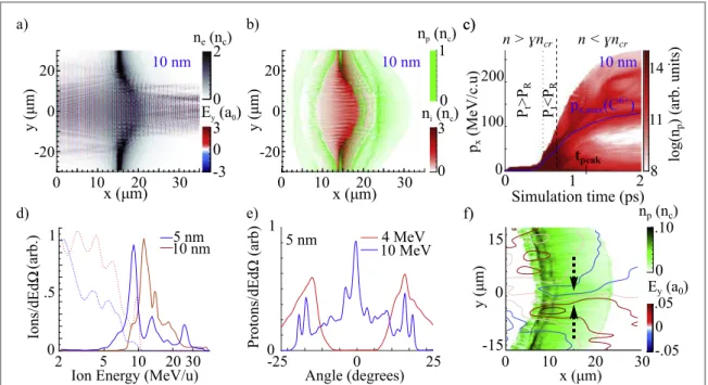
ion density in this phase is shown infigures5(a) and (b), together with the transverse electric field Eyshowing laser transmission through the target. Ponderomotive pressure inhibits the front surface sheath, and an almost uniform capacitor-like Exfield is produced through-out the transparent region due to hot-electrons exiting the
rear-surface.
Due to their higher charge-to-mass ratio, protons inside the carbon plasma respond more quickly to this bulkfield and outrun the C6+ions(figure5(c)), gaining a minimum velocity equal to that at the C6+ion front, vcf. This results in an abundance of protons withvpvcf. Sincev vp c=2due to different charge-to-mass ratios,
total species separation occurs if d 2 v v dt v t 2dt
0 p c 0 p
ò
t( - ) =ò
t ( ) , where d is the target thickness when the bulkfield is generated and τ is the acceleration time. From the simulations, the time-average field during acceleration is Exb» ´6 1011V m−1, and lasts fort »750fs. Assuming a static potential, the minimum target thickness for proton expulsion is therefore d(e m Ep) xbt2 2»15μm, much greater thand »d n0 0 gnc»3μm at the time the target becomes transparent in the simulation for this initial
d0=20 nmfoil.
Modulated spectra have been reported previously due to acceleration of comoving protons close to a high-Z ion front[32–35], where only a small fraction of the protons are affected. These simulations however show a bulk field which causes almost complete expulsion of protons from the target. Indeed, we note that for such thin targets, the initial spatial location of the hydrogen, either in the bulk or on the target surface, makes little difference to the late-time dynamics. Figure5(c) shows the temporal evolution of the on-axis forward momentum pxof the protons with px,maxof the C6+. The ion energy gain occurs mostly when the target is
transparent, and is not due to RPA[22], unlike previous reports of species separation from ultra-thin targets [10,11]. Below vcfthere are almost no protons, resulting in peaked on-axis spectra(figure5(d)), as measured
experimentally.
This species separation occurs for all target thicknesses up to 100 nm. For d0=100 nm, the target remains overdense and protons are not completely driven out, unlike for d0<20 nm. However, there is still significant species separation at the sheath front due to the large Debye length, manifesting in a spectral peak in the proton beam matched to the maximum carbon energy. Further simulations with the addition of a hydrogen-rich surface contaminant layer to the target enhances the proton number in this peak, but such contaminant layers are not necessary to observe this effect. Species separation is most prominent for the thinnest targets, which may indicate why spectrally modulated beams were not observed at d0=500 nm.
At later times, the minimum proton energy in the buffered layer increases, giving a proton peak energy Epeak
that follows the carbon front velocity vcf. Simultaneously the maximum energy of the tail of the proton
distribution Emaxincreases due to acceleration in the sheath, leading to a high energy proton tail beyond the peak
Figure 5. From simulation:(a) charge density of electrons and overlaid transverse electric field Eyshowing target transparency, and(b)
charge density of C6+(red) and protons (green) near the peak of pulse,t
peak, for d0=10 nm;(c) evolution of pxfor protons on-axis,
with px,maxfor C overlaid(blue line) for d0=10 nm;vertical dashed(dotted) lines indicate different density (pressure) regimes; (d)
spectra of protons(solid) and C6+(dotted) witnessed in 1» msr on-axis for d 5, 10 nm;
0= (e) angular proton distribution at 4 and
10 MeV for a 5 nm target;(f) npattpeak+200fs with overlaid electrostatic Eycontours for d0=5 nm.
6
with wide divergence, as witnessed experimentally. Though the carbon plasma exhibits transverse spatial modulation, most of the protons have been shielded from thisfilamentation, as can be seen by comparison of the spatial properties of the two species infigure5(b).
Expulsion of protons from the carbon plasma results in strong angular beam dependence on proton energy, as seen for d0=5 nmat the end of acceleration(figure5(e)). At low beam energies, equivalent to the 4 MeV layer in the RCF, no axial protons are observed. In the initial expansion phase, electron heating is localised to a small transverse extent similar to the longitudinal size of the expanding plasma∼w0. The transverse to
longitudinal electricfield ratio E Ey x» nye nxe ~ 13
¶ 
¶ results in rapid transverse expansion[36]. The remnants
of this initial expansion are responsible for the ring observed experimentally at low energy, and the cone-like expansion visible on the optical probe. The low axial density of the expansion measured from the interferometry is therefore likely to be caused by this transverse expansion, and can be enhanced by laser propagation through the relativistically transparent region[37].
At higher energies, a low divergence component( 5» ) close to the laser-axis becomes apparent, consistent with the central beams seen experimentally. The sheath of the self-generated cone has a focussing effect on protons still being accelerated within the evacuated region, similar in action to other laser-triggered charged particle lenses[38,39]. The focussing field, shown in figure5(f), is maintained until the end of the interaction, producing a collimated beam on-axis. For thicker targets, there are sufficient protons in the target that a larger fraction remain in the central region, reducing the collimating effect. A static B-field of magnitude»2kT also forms, and though providing an order of magnitude lower force on the protons than the electricfield, acts to pinch the forward laser driven relativistic electrons, further enhancing the space charge collimatingfields during the laser plasma interaction. Note that only the protons nearest the laser-axis are refocused by this collimating field; further off-axis more divergent protons continue to be accelerated in the hot electron driven sheath fields to high energies. As previously discussed, such a highly divergent but lowerflux beam was also witnessed in the experiment.
LP simulations showed only minor differences from CP; the target became transparent slightly earlier (∼150 fstL). In both cases, the laser–plasma interface quickly deforms, reducing the electron heating
suppression expected for CP. This explains the lack of dependence on polarisation in the experiment, except for the very thinnest targets where LP causes the target to become too underdense by the peak of the pulse, resulting in negligible acceleration[22].
Further simulations were performed for d0=20 nm, varying laser intensity and w0while keeping the 2D
transverse integral constant, equivalent offixing the laser power and varying focusing. Fora0<2, the target
remains overdense, radiation pressure never overcomes plasma pressure, and buffering is not observed. For
a0> , the target becomes transparent before the peak of the pulse, and both species gain energy during3 relativistic transparency, as infigure5(c). However, for a0=8.5as should be implied from our experimental low power focal spot measurement(w0= μm), E8 p=35 MeV. The lower experimental value therefore
implies a lower focal intensity, likely due to poor laser near-field uniformity combined with hydrodynamic expansion of the plasma mirror fort » ps.L 1
Forfixed target thickness d0and varying the normalised vector potential froma0=2to a0=10, the
simulations suggest a scalingEpµa0, following the ponderomotive scaling typical of thermally driven
acceleration. Varying w0withfixed a0makes no appreciable difference to Ep. However, Epis dependent on the
ratio of carbon to proton mass in the target[24], with a trade-off between higher energy but fewer protons. Further simulations performed with near optimal parameters for the Vulcan Petawatt system(a0=11,
w0» μm, d8 0=20nm) resulted in Ep»50 MeV, and Emax>100 MeV.
4. Conclusions
We have demonstrated the generation of high charge, narrow energy-spread proton beams for thefirst time from an initially homogenous thermally expanding plasma. The beams are produced by the irradiation of ultra-thin foils(5–100 nm) with an intense (>1019W cm−2) laser. Due to their higher charge-to-mass ratio, these
proton beams are buffered ahead of, and protected from, transverse Rayleigh–Taylor-like instabilities in a more slowly expanding carbon plasma. For reducing target thickness, the buffered beam reduces in divergence down to»8◦for a 5 nm target. 2D particle-in-cell simulations reveal the increased beam collimation is due to a plasma
space-charge lensing effect, and also demonstrate this mechanism can be scaled to higher laser intensity with proton energies∝a0. The contrasting spectral characteristics of the ring and central beam highlight the
importance of combined beam profile and spectral measurements when reporting narrow energy spread ion beams, as the properties of the whole beam cannot be extrapolated by integrating over the whole beam, or indeed by sampling over limited angular acceptance. Importantly, this method of generating narrow energy spread beams produces high charge( 50» nC) beams without the added complexity of microstructured targets in
7
previous experiments on spectrally peaked beams from thermal acceleration[3–5]. Our demonstration of buffered acceleration from relativistically transparent targets will therefore be attractive for nuclear physics applications.
Acknowledgments
We acknowledge funding by EPSRC/RCUK grants EP/E035728/1, EP/K022415/1 and STFC grant ST/ J002062/1. We thank the OSIRISconsortium(UCLA/IST) for use of OSIRIS, and the support of the LMU’s
MAP-service centre to provide DLC foils.
References
[1] Clark E L et al 2000 Phys. Rev. Lett.84 670
[2] Snavely R A et al 2000 Phys. Rev. Lett.85 2945
[3] Schwoerer H et al 2006 Nature439 7075
[4] Hegelich B et al 2006 Nature439 7075
[5] Pfotenhauer S M et al 2008 New J. Phys.10 3
[6] Dollar F et al 2011 Phys. Rev. Lett.107 065003
[7] Yin L et al 2007 Phys. Plasmas14 056706
[8] Qiao B et al 2010 Phys. Rev. Lett.105 155002
[9] Yu T P, Pukhov A, Shvets G and Chen M 2010 Phys. Rev. Lett.105 065002
[10] Kar S et al 2012 Phys. Rev. Lett.109 185006
[11] Steinke S et al 2013 Phys. Rev. STAB16 011303
[12] Zhang X et al 2007 Phys. Plasmas14 123108
[13] Esirkepov T et al 2004 Phys. Rev. Lett.93 175003
[14] Robinson A P L et al 2008 New J. Phys.10 013021
[15] Yan X Q et al 2008 Phys. Rev. Lett.100 135003
[16] Klimo O et al 2008 Phys. Rev. STAB11 031301
[17] Henig A et al 2009 Phys. Rev. Lett.103 245003
[18] Palmer C A J et al 2012 Phys. Rev. Lett.108 225002
[19] Willingale L et al 2009 Phys. Rev. Lett.102 125002
[20] Henig A et al 2009 Phys. Rev. Lett.103 045002
[21] Yin L et al 2006 Laser Part. Beams24 291
[22] Yin L et al 2011 Phys. Plasmas18 063103
[23] Jung D et al 2013 New J. Phys.15 023007
[24] Jung D et al 2013 Phys. Plasmas20 083103
[25] Thaury C et al 2007 Nat. Phys.3 424
[26] Ma W et al 2011 Nucl. Instrum. Methods Phys. Res. A655 53
[27] Nürnberg F et al 2009 Rev. Sci. Instrum.80 3
[28] Kar S et al 2008 Phys. Rev. Lett.100 225004
[29] Mančić A et al 2008 Rev. Sci. Instrum.79 073301
Doria D et al 2009/10 CLF Annual ReportRAL, UKp 78 [30] Dollar F et al 2012 Phys. Rev. Lett.108 175005
[31] Fonseca R A et al 2002 Lecture Notes in Computer Science vol 2331 (Berlin: Springer) p 342 [32] Decoste R and Ripin B H 1978 Phys. Rev. Lett.40 34
[33] Allen M et al 2003 Phys. Plasmas10 3283
[34] Bychenkov V Yu et al 2004 Phys. Plasmas11 3242
[35] Robinson A P L, Bell A R and Kingham R J 2006 Phys. Rev. Lett.96 035005
[36] Bin J H et al 2013 Phys. Plasmas20 073113
[37] Powell H W et al 2015 New J. Phys.17 103033
[38] Toncian T et al 2006 Science312 410
[39] Kar S et al 2008 Phys. Rev. Lett.100 105004
8