HAL Id: lirmm-02303117
https://hal-lirmm.ccsd.cnrs.fr/lirmm-02303117
Submitted on 2 Oct 2019
HAL is a multi-disciplinary open access
archive for the deposit and dissemination of
sci-entific research documents, whether they are
pub-lished or not. The documents may come from
teaching and research institutions in France or
abroad, or from public or private research centers.
L’archive ouverte pluridisciplinaire HAL, est
destinée au dépôt et à la diffusion de documents
scientifiques de niveau recherche, publiés ou non,
émanant des établissements d’enseignement et de
recherche français ou étrangers, des laboratoires
publics ou privés.
Abderrahmane Kheddar, Stéphane Caron, Pierre Gergondet, Andrew
Comport, Arnaud Tanguy, Christian Ott, Bernd Henze, George Mesesan,
Johannes Englsberger, Máximo Roa, et al.
To cite this version:
Abderrahmane Kheddar, Stéphane Caron, Pierre Gergondet, Andrew Comport, Arnaud Tanguy, et
al.. Humanoid robots in aircraft manufacturing. IEEE Robotics and Automation Magazine, Institute
of Electrical and Electronics Engineers, 2019, 26 (4), pp.30-45. �10.1109/MRA.2019.2943395�.
�lirmm-02303117�
Humanoid robots in aircraft manufacturing
Abderrahmane Kheddar, St´ephane Caron, Pierre Gergondet, Andrew Comport, Arnaud Tanguy, Christian Ott,
Bernd Henze, George Mesesan, Johannes Englsberger, M´aximo A. Roa, Pierre-Brice Wieber, Franc¸ois Chaumette,
Fabien Spindler, Giuseppe Oriolo, Leonardo Lanari, Adrien Escande, Kevin Chappellet, Fumio Kanehiro
and Patrice Rabat´e
Abstract—We report results from a collaborative project that investigated the deployment of humanoid robotic solutions in air-craft manufacturing for some assembly operations where access is not possible for wheeled or rail-ported robotic platforms. Recent developments in multi-contact planning and control, bipedal walking, embedded SLAM, whole-body multi-sensory task space optimization control, and contact detection and safety, suggest that humanoids could be a plausible solution for automation given the specific requirements in such large-scale manufacturing sites. The main challenge is to integrate these scientific and technological advances into two existing humanoid platforms: the position controlled HRP-4 and the torque controlled TORO. This integration effort was demonstrated in a bracket assembly operation inside a 1:1 scale A350 mock-up of the front part of the fuselage at the Airbus Saint-Nazaire site. We present and discuss the main results that have been achieved in this project and provide recommendations for future work.
Index Terms—Humanoids, aircraft manufacturing.
I. INTRODUCTION
February 21, 2019: for the first time, two humanoid robots, the CNRS-LIRMM’s position controlled HRP-4 and DLR’s torque controlled TORO accessed the Airbus civilian airliner manufacturing plant at Saint-Nazaire, France, and achieved the final demonstration of the EU collaborative project Comanoid1
that gathered four academic Europeans partners, a Japanese na-tional research institute; and the end-user industry, Airbus. The goal of Comanoid is to path the way toward the eventuality, the feasibility and the plausibility of deploying humanoid robotic technology as an automation solution to achieve specific non-added value tasks in aircraft manufacturing operations.
Comanoid focuses on showing precise accessibility (namely into areas where wheeled robots cannot be deployed) through whole body multi-contact planning motion with advanced em-bedded 3D dense SLAM localisation and visuo-force servoing capabilities under safety constraints. Another CNRS-AIST JRL and Airbus bilateral project (which is not discussed here) complements Comanoid with more complex manipulation
A. Kheddar, S. Caron, A. Tanguy, are with CNRS-University of Montpellier, LIRMM, France.
A. Comport, is with CNRS-University de Nice, L2S, France.
A. Kheddar, P. Gergondet, A. Escande, K. Chappellet, F. Kanehiro are with CNRS-AIST JRL, Tsukuba, Japan.
C. Ott, B. Henze, G. Mesesan, J. Englsberger, M. A. Roa are with DLR -German Aerospace Center, Oberpfaffenhofen, -Germany.
Pierre-Brice Wieber is with Univ. Grenoble Alpes - Inria, France. F. Chaumette, F. Spinder are with Inria, Irisa Rennes, France. G. Oriolo, L. Lanari are with Sapienza University of Rome, Italy. Patrice Rabat´e is with Airbus, Saint-Nazaire, France.
Manuscript received March 15, 2019; revised Xxxx XX, 2019.
1comanoid.cnrs.fr
tasks such as fast torqueing, flexible cable assembly, cleaning and cockpit assessment operations.
Despite the considerable advances in many fundamental and technical aspects of humanoid robotics research, public and private subsidy funds became more demanding for the motiva-tions and perspectives behind research in humanoids, and even explicitly seeking for so-called “killer” application(s). Besides pure robotics, humanoid robotics can be useful in research related to embodiment and consciousness, and more general in neuro- and cognitive sciences. They are also envisioned in sectors of entertainment, as receptionists and in various social interactions, e.g. as “assistants” for frail persons (note that not all these applications require having robots with legs); this is part of the business plan of companies like SoftBank Robotics (Japan) and PAL robotics (Spain). Other services like disaster emergencies, nuclear power plant dismantling, space exploration and space extra-vehicular activities also consider to some extent humanoids as remote intervention robots. Yet, no industrial sector has shown needs in terms of humanoid robots for manufacturing. The exception is the Glory factory at Saitama, Japan, where the assembly of money handling machines and alike, incorporates humanoid (torso) robots for manufacturing, the Nextage robots.
Our work is the outcome of many years of discussions and exchanges with the formal Airbus Group Innovations as for what solution is suitable for robotic automation of non-added value tasks. At early discussions, humanoid robots were not considered because of their complexity, non-availability, and slow progress. The next section discusses briefly the needs in automation that might call for a bipedal solution. The following sections present all the technological bricks developed in the framework of the Comanoid collaborative project, and the demonstrator achieved within the project.
II. WHY HUMANOID ROBOTS IN AIRCRAFT MANUFACTURING AUTOMATION?
On 26 February 2014 (5 years ago), a workshop was organized in the premises of the French embassy in Tokyo, gathering academic experts in robotics to complement on-going Airbus internal investigations concerning what robotic technology is best for automating non-added value tasks (for Airbus workers), such as measuring and positioning (printing) the bracket templates in the cargo hold and other hard-to-access areas? Initial inquiries suggested that a legged robot carrying manipulator arms could be one solution. Then the other question was: how many legs/arms?
At first, humanoid technology was not considered. It was thought that such robots were not reliably stable with only two
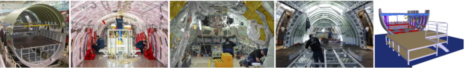
Fig. 1: Examples of the working areas and conditions in aircraft manufacturing sites. From left to right: cargo area; kneeling and using a small ladder to access the roof; cockpit area; removal of temporary floor to access in between levels; finally, CAD digital model at 1:1 scale of the A350 mockup used to demonstrate the technologies, gathering most of these scenarios.
legs. Therefore, hexapods or quadruped Centaur-type robots were considered. Yet, multi-legged solutions come with some practical limitations and drawbacks: (i) the stability benefits of a larger support area in multi-legged robots (and even wheeled ones) are reduced or lost when the mounted manipulators approach or go beyond the support borders; (ii) indirectly related to (i) multi-legged occupy a larger shop-floor space that could not be feasible in many areas of the aircraft because of the confined, cluttered or narrow spaces, e.g. human workers crawl to access the cockpit area; and (iii) the cost that can be more expensive with multi-legged robots porting dual arm manipulators. In light of these, and with the already available demonstrations of HRP-2 humanoid multi-contact technology, illustrating that a humanoid can also use its other limbs for contact support (as humans do), we decided with Airbus to investigate further humanoid technology solutions.
A. Context and automation needs
The aeronautical industrial context in final assembly line and major component assembly can be best explained through the following specificities:
• large structures, millions of parts: for example, the A380 has more than one million rivets, and there is a need to assemble about two-digit dozens of thousands of supports (for cables, tubes, brackets, etc.)
• low production rate: for the A320 family, it is 1.5
airplanes per day, and for the A380 it is 4 per month; this rate could increase if production delays are avoided
• very high quality requirements: for example, hole posi-tioning requires sub-millimetre precision, and hole nor-mality adjustment requires less than one degree clearance
• skilled operators: that we wish to allocate to complex and cognitive high-value tasks, freeing them from simple, repetitive and heavy non-added value tasks
• workspace: it is centred around the fuselage inside and outside, with limited space; it is generally a crowded area. Robots’ arrival in aeronautic manufacturing plants is more recent (90s), due to low accuracy of industrial robots mostly designed for automotive industry. First applications consisted in drilling holes on medium-size components such as nose fuselage structures. Until recent years, there was no automated mean in the final assembly line, except the circumferential junction of A340 automation, but it has been abandoned on the following programs because it was not flexible enough.
For these reasons, Airbus seeks for collaborative robots capable of performing assembly tasks inside the aircraft. Few
years ago, Airbus Puerto-Real plant made very first experi-ments with the Nextage Kawada’s robot in order to perform simple assembly tasks. To our knowledge, apart from this first experiment, no real work has been achieved and published on the use of humanoid robots in aeronautic industry.
The main interest concerns non added-value tasks, as they are dangerous, present considerable health risks such as high repetitive strain injury, require high precision and low dexter-ity. In Comanoid we have targeted the tasks of pattern printing or bracket positioning on the structure, as they are made almost everywhere in the fuselage, and do not require heavy payload nor dextrous manipulation. The main goal was to show the ability to reach the working places and be precise in both localization and positioning the end effector in the structure.
In the frame of another research program, four use-cases of relative complexity were identified: (i) circuit breaker automa-tion, that requires operation in cluttered spaces; (ii) hydrofuge protection and cleaning that requires managing equilibrium and in-line tool trajectory planning; (iii) torqueing automation that requires multi-contact balance control in dynamic motion and force control; and (iv) system installation that requires manipulating flexible objects. Other tasks such as drilling and cockpit end-phase systems checks were also suggested.
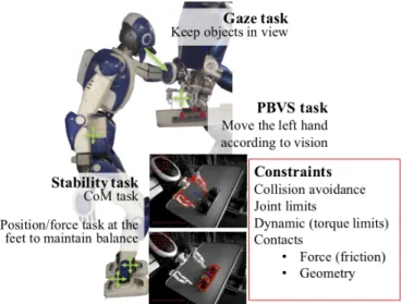
B. Constraints
Accessibility and manipulation needs are already very chal-lenging. The additional constraints under which robots operate render these challenges nearly unreachable, see Fig. 1:
• any robot shall operate and share the same space with
human workers and be safe in all circumstances;
• humanoid falling shall be demonstrated in worst
condi-tions on human and even on the airplane structure;
• the robot shall be able to access any spot starting from any other, and travel between the three working levels using human means, i.e., without requiring changes in the manufacturing infrastructure;
• no external sensors, such as external cameras, are al-lowed. However, bringing extra lighting is allowed;
• safety certification, compliance with established internal regulations and procedures
The good news is that workers follow strict procedures and rules; the CAD model of any piece or part of the airplane is available with its exact shape and inertia parameters; and a digital mock-up is updated all along the assembly process.
III. BASIC TECHNOLOGICAL REQUIREMENTS
In the light of the previously established requirements and needs, we have identified the following must-have technolo-gies to be developed further in the Comanoid project and implemented on the HRP-4 and TORO humanoid robots by the end of the project: (i) multi-contact planning and control; (ii) walking; (iii) embedded localization and mapping; (iv) integrating visual and force control into the task-space opti-mization control; and finally (v) contact detection and safety. A. Multi-contact planning and control
In many areas illustrated in Fig. 1, workers operate often in very unergonomic postures. In such cases, they use multi-contact postures to relax stress, be in better equilibrium or cast their body posture (e.g. contact with knees, shoulders, back). Humanoids shall be endowed with similar multi-contact behaviors, which is a key technology in Comanoid. It allows transforming a humanoid robot into a reconfigurable multi-limb system that can adapt to narrow spaces, increase its equilibrium robustness and even its manipulation capabilities. 1) Multi-contact planning: A recent review in multi-contact technology [1] reveals that this problem is consensually ap-proached through a multi-level computation. The first level plans contacts around a sort of free-motion pre-planed “guide” that will exploit some properties under various hypothesis (there are many variants), but having as an output a set of contact sequences and associated transitions. In a second phase, the latter are the input for a simplified model (e.g. CoM) to generate consistent centroidal dynamics trajectory under balance criteria (presented later). In the last phase, this generated trajectory is the input to the whole body controller, which deals also with other task objectives and constraints. The problem in such multi-level computation is to make each phase likely feasible for the upcoming one, and make sure that if any phase turns out to be not feasible for the given input, the latter is quickly re-computed from the current state. Although impressive results have been obtained, this approach does not work well in practice. In the context of manufacturing, it is certainly not a good idea to plan contacts as if we do not know at all where and how they should be made. Assembly operations are quite repetitive in many aspects, only few variations are to be dealt with locally.
Our approach is to exploit knowledge from how humans op-erate in similar circumstances and considering that predefined procedures dictate grossly what contact sequence is necessary to conform both safety and task needs. Then, the posture that the robot takes in order to achieve a given task in a multi-contact setting is computed, including task forces [2]. Indeed, the force required for a given task has great influence on the configuration to be taken. Moreover, the task to be made would suggest additional contacts to be established not only to increase the equilibrium robustness, but also to increase the operational force by creating additional kinematic loops [3] and exploiting internal force distribution.
After finding the contact configuration suitable for each operation, special attention is required for the realization of transitions between different multi-contact poses. In order to
realize dynamic contact transitions, and avoid disadvantageous quasi-static motions, we adapted the DCM framework from dynamic walking to the generation of multi-contact locomo-tion tasks [4]. The generated DCM and CoM trajectories are then compatible with a given sequence of multi-contact poses. In addition to the CoM motion also the timing of the end-effector motions, namely the stance durations and the contact transition timings, are optimized.
2) Multi-contact balance and control: The multi-contact planning phase generates desired contacts and a CoM to track at best (or exactly) by the whole-body controller, among other task objectives (such as manipulation). The HRP-4 is controlled using task-space objectives in the sensory space, formulated as a weighted and constrained quadratic program. It includes visual and force servoing, see section III-D, and various tasks templates to achieve a contact, sustain a contact, remove a contact, force and admittance control [5], etc.
The general balance condition is written in a bilinear form in terms of CoM position and its acceleration and contact forces. For bounded convex CoM positions we can obtain feasible CoM accelerations as a 3D cone. For bounded convex CoM accelerations we can obtain feasible CoM positions as a 3D convex hull [6]. Resultant geometrical shapes can be used and integrated in both planning and control [1].
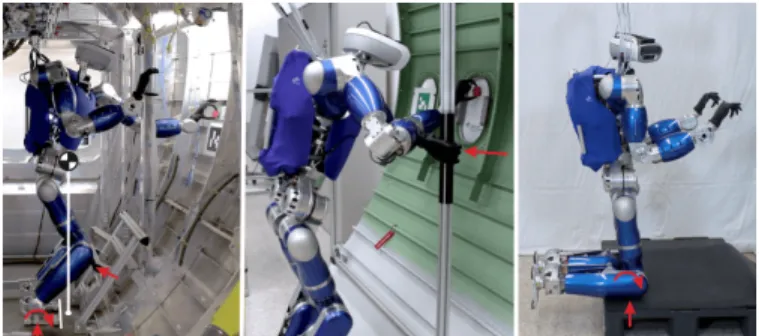
Fig. 2: Different multi-contact situations; from left to right: feet plus knee support, hand support, and full kneeling.
Multi-contact tasks with the torque controlled humanoid robot TORO are achieved with a passivity-based control framework [7], [8]; the following four steps are summarized within a single force based optimization problem: (i) realiza-tion of a desired wrench to stabilize the CoM at a desired equilibrium; (ii) implementation of desired impedance forces for the end-effectors performing the manipulation tasks; (iii) distribution of the resulting overall wrench to the wrenches acting at the available end-effectors in contact via a “grasp” matrix; and (iv) realization of all end-effector wrenches via the robot’s joint torques, see [7]–[9], where the passivity properties are analyzed. Passivity is of utmost importance whenever the robot has to interact with an unknown but passive environment. This control framework has been successfully applied to several multi-contact configurations related to the given aircraft manipulation use-cases, see Fig. 2.
B. Walking
No humanoid robot is currently able to walk around an Airbus manufacturing facility with the same reliability as a
human worker. Since this environment is shared with human co-workers, reliability is also a major aspect in the safety of the robot, of the airplane structure, and of co-workers. Reliability and safety of humanoid robots are complex issues, for which no meaningful quantitative measure currently exists. As a result, and since the field of legged locomotion is still maturing, the Comanoid consortium’s strategy has been to de-velop reliability and safety for a diverse range of approaches to walking motion generation and control, instead of committing to a single one.
The modeling of legged locomotion relies on a few simple physical principles [10]. The Newton equation of motion makes it clear that the robot needs contact forces fi in order
to move its Center of Mass (CoM) c in a direction other than that of gravity g, while the Euler equation of motion makes it clear that the position of the CoM with respect to contact points si is critical to keep the angular momentum L of the
robot around its CoM under control: (
m (¨c − g) =P fi
˙
L =P(si− c) × fi
(1) where m is the mass of the robot. These are the elements of motion to maintain balance, but how? Making sure that the robot is always able to reach a cyclic motion or an equilibrium point in a few steps is a simple and effective way to guarantee that it is able to avoid falling. This also provides a simple way to detect the risk of an imminent fall, in order to trigger fall mitigation behaviors when appropriate.
The Comanoid consortium adopted a standard multi-stage framework for walking motion generation and control: (i) a short sequence of step positions and phase durations is pro-posed depending on robot current and goal states and the environment (obstacles and people); (ii) the resulting motion of the CoM and contact forces are computed, making sure that a cyclic motion or an equilibrium point can be reached within a few steps; (iii) the robot is controlled to realize the computed CoM motion and contact forces.
We devised several approaches within this common frame-work, to improve reliability and safety. Some address stages (i) and (ii) separately [11], and others in a single stage [12]. This is slightly more involved numerically, but it improves the robot’s capacity to react effectively to a dynamic envi-ronment. In static environments, stages (i) and (ii) can be considered once every few steps. Otherwise, e.g. with workers moving around, these stages are reevaluated more often, using approaches based on Model Predictive Control (MPC).
Capturability approaches guarantee that the robot is consis-tently in a viable state and is always able to stop safely [12]. Alternative ones investigate the more general concept of boundedness [13]. One approach to integrate safety guidelines with respect to surrounding humans is to adapt the current goal of the robot w.r.t the current state of the environment [14]. One can also integrate collision mitigation and passive safety constraints directly in a combination of stages (i) and (ii) [12]. This is more involved numerically, but it improves the robot’s capacity to navigate safely in the presence of workers.
To negotiate uneven ground and stairs, the height of the CoM of the robot should be adjustable, thus introducing
nonlinearities in stage (ii). These nonlinearities are sometimes neglected, but to a risk of failure. We handle them explicitly by considering a piecewise linear 3D trajectory of the Divergent Component of Motion (DCM) [11], or we bound them by con-straining the height variations of the CoM above the ground, adapting the capturability and boundedness accordingly [15]. This diversity of approaches has been used to demonstrate two different humanoid robots capable of navigating in a typical Airbus environment, walking reliably to their exact destinations in order to complete effectively the assigned manipulation tasks. This requires a tight integration of walk-ing with visual servowalk-ing and Simultaneous Localization And Mapping (SLAM), multi-contact phases and safety guidelines. This tight integration is arguably the biggest achievement of the project, walking being addressed not independently from navigation, manipulation and safety issues.
C. In-site and in-craft localization and mapping
Autonomous SLAM in aircraft manufacturing is a funda-mental capability for practical use of humanoid robots in a real-world setting. Few real-time approaches have been proposed that are able to account for dynamic environments and long-term incremental changes (manufacturing process, lighting variation) while maintaining positioning accuracy or tolerating loss of tracking. Moreover, assembly operations re-quire continuous correspondence between the evolving digital mockup and the reality of the airplane assembly. Subsequently, semantic knowledge is highly necessary.
Image-based keyframe navigation was used for its efficiency and accuracy for humanoid positioning, since it allows closing the feedback control loop in the sensor space, subsequently avoiding drift, improving robustness, and allowing loop clo-sure and relocalisation (see results in Section IV).
1) Keyframe SLAM and image-based navigation: A direct multi-keyframe approach is used to perform RGB-D SLAM for navigation [16]. The sensor pose ξ ∈ se(3) is estimated w.r.t. the set of closest key-frames by minimising the error between the current frame and a predicted one. The current measurement vector for each intensity and depth i is defined as Mi = [P>i Ii]> ∈ R4. The predicted keyframe M∗i ∈ R4
is obtained by blending the n closest keyframes (typically 5) at the last pose estimate. The point-to-hyperplane ICP approach [17] is then used to estimate the pose iteratively from the following error function:
ei(ξ) = N∗>i (M∗i − w(Mi, ξ)) (2)
where the normals N∗>i ∈ R4 are computed once on the
reference 4D measurement vector, and w(·) is the warping function that transforms the current image to the reference, based on the current pose estimate.
This basic alignment procedure is extended to large envi-ronments by using a keyframe-graph, built and refined incre-mentally as mapping is performed. In order to take advantage of the topometric keyframe representation, the target position is given as a sensor-based keyframe to reach. This allows the direct image-based error defined in (2) to be minimised by the robot controller. This effectively allows the robot to position itself with high accuracy locally whilst tolerating global drift.
2) Map reuse, place recognition and time-varying environ-ments: Due to the complexity of the manufacturing site with factors such as workers, tools and assembly increments, a prior key-frame graph was created from a static environment and then reused online. To ensure robot positioning, the pose uncertainty and sensor-based error were monitored to deter-mine tracking loss and trigger relocalization (pose estimation with respect to the nearest keyframes). In addition, the robot’s viewing direction was actively controlled to look at the closest keyframes to improve robustness.
In practice, partial keyframe maps were acquired for each task workspace of the robot. These sub-maps were only connected topologically. They were then reloaded online ac-cording to the robot’s location. During the demonstrations, this proved to be very efficient since there were even more people in the environment than in a typical work setting.
(a) Synthetic 3D model of the A350 aircraft mock-up
(b) Samples without ICP (c) Samples with ICP
Fig. 3: Overlays of RGB images and their ground truth labels projected from the synthetic 3D model of the aircraft mock-up (3a), initially using global registration (3b) and after post-refinement using an ICP algorithm (3c) .
3) Semantic real-time mapping: Planning and control al-gorithms require higher-level knowledge about the environ-ment surrounding the robot. A rich source of information for learning this knowledge is the Airbus digital mock-up. A real-time semantic segmentation network was developed where classes are learned from the labelled digital mock-up. The segmentation network is fine tuned for the given use-case and trained in a semi-supervised manner using noisy labels. The method is optimised for real-time performance and integrated
with ROS to provide semantic reconstruction for navigation. Semantic information can also be fed back to the SLAM. The measurement vector M is extended to simultaneously minimise photometric, geometric and semantic costs in real-time [18]. The approach has been shown to robustly construct a labeled large-scale 3D map relevant to robotic tasks. In-situ experiments at Airbus validated our approach, see Fig. 3. D. Visual and force control
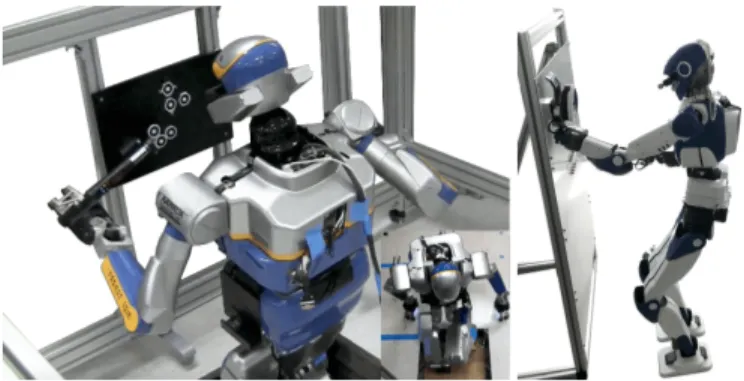
1) Visual tracking and servoing: For accurate manipulation, the amount of observed data is not sufficient to provide its lo-calization through the SLAM described above. For this reason, particular object detection, visual tracking, and visual servoing techniques have been developed in Comanoid. The object detection is done using classical key-point matching methods and provides an initial localization (full pose) between the observed object and the vision sensor. The object and its successive poses are then tracked during the humanoid motion thanks to a modular real time model-based vision tracker (MBT). This MBT is available for the community in the latest release of ViSP [19]. It can combine low level edges extracted in the image, textured point of interest, as well as depth [20] when an RGB-D camera is available, which is the case for both TORO and HRP-4.
Once visual data are available at high rate (10Hz in our case), they can be embedded in a closed loop visual servoing scheme. However, to be combined with the QP controller of HRP-4, it has been necessary to go from the classical kinematics modeling of the visual features to their dynamic modeling. This modeling step is described in [21]. It is then possible to consider tasks, such as gaze control or set-point reaching, occlusion avoidance or preserving the visibility of an object, as any other robotics task and constraint.
The object detection, visual tracking and visual servoing described above have been both implemented on TORO (see Figure 4) and HRP-4 (see Figure 5, Section IV-A and ac-companying video). Note that with HRP-4, a tracking of both the object of interest and the HRP-4 left-arm gripper is done simultaneously, which allows a robust and accurate positioning of the gripper with respect to the object to be manipulated.
2) Force control: Force control is necessary in many op-erations such as pulling the circuit-breakers and gluing the bracket on the fuselage. In order to complement vision, force control is implemented on both robots. Whereas force control on TORO is rather straightforward due to its torque control capabilities, it requires specific considerations for the position controlled HRP-4.
First, contact or interaction forces being decision variable of the QP, constraints such as non-sliding linearized friction cones, bounds on applied forces (in any direction) that might be dictated by the task, or minimal (threshold) force required to sustain a contact, can easily be added. However, in order to servo a given terminal point to a force, we need to decide that desired force. If the desired force is user-given, it can be realized by an admittance task that is part of the QP formulation [5]. Yet, defining arbitrary forces to hold a contact may unnecessarily restrict the motion of the robot, especially
(a) (b)
Fig. 4: Visual tracking results obtained with TORO: (a) bracket tracking using edges and depth (left: image with edges extracted and model projected from the estimated pose, middle: depth map with model used projected from the same pose, right: robot configuration), (b) fuselage tracking using edges and key-points with TORO (left: image with edges and key-points used and model projected from the estimated pose, right: robot configuration).
(a) (b)
Fig. 5: Visual tracking results obtained with HRP-4: (a) bracket tracking using edges and depth (left: image with edges extracted and model of the bracket projected from the estimated pose, middle: depth map with bracket model used projected from the same pose, right: image with edges and key-points used to track the gripper, and gripper model projected from the estimated pose), (b) circuit breaker panel tracking (left: image with edges and model projected from the estimated pose, right: same image with edges and gripper model projected from the estimated pose).
in a multi-contact setting. For instance, in the HRP-4 example of section IV-A, we want to apply with the left gripper a force of about 10 N in the normal direction of the fuselage surface to glue the bracket, but we would rather avoid specifying a particular force for the right gripper leaning on the structure to support the motion. In this case, we simply require that force to be greater than a given threshold [5].
E. Safety and contact detection
Safety is critical in human-robot colocated space, as in aircraft manufacturing; but it is also important to preserve the integrity of the humanoid itself as well as the surrounding environment. While the problem of safe coexistence with hu-mans had been widely addressed for fixed-based manipulators, there were no results for humanoids before Comanoid.
Designing robust walking controllers that perform reliably is already one way to increase the intrinsic level of safety, see section III-B. As a more systematic, complementary approach, we have identified a set of safety guidelines [22], from which it is possible to derive several safety behaviors, grouped in three categories. Override behaviors (e.g., emergency stop) will stop the execution of the current task and lead to a state from which normal operation can only be resumed by means of human intervention. Temporary override behaviors (e.g., evasion [14]) will also suspend task execution, but only for the limited amount of time needed to handle the safety concerns, after which task execution is automatically resumed. Finally, proactive behaviors (e.g., human visual tracking or footstep adaptation) do not stop the task, but try to increase the overall
safety level by calling for a modification of the current robot activity. The activation of the safety behaviors, integrated in an MPC control framework, is orchestrated by a suitable state machine based on robot on-board sensors feedback.
Safe falling strategies are important for minimizing robot damages in case of loss of balance. Our approach for the HRP-4 humanoid, tries to actively reshape the robot’s toward one favorable configuration from a set that has been identified in advance [23]; control gains are then adapted in real time to comply with the post-impact dynamics. For the TORO robot, the use of passive protections (pads, airbags) has been found to bring a significant reduction (over 50%) of the accelerations experienced by the robot linkages during the fall; moreover, an active falling strategy based on energy minimization can be adopted to minimize impact velocities at the elbows. Note that active falling strategies can be considered and realized as override behaviors in the above safety framework.
Intentional or accidental contact detection is already em-bedded in some commercial fixed-base manipulators, while contact localization and force reconstruction was achieved in prototypes using external depth cameras; again, no results for humanoid robots were available before Comanoid. A number of methods to solve this problem were developed during the project, either based on the mismatch of expected vs. measured torques [24] or using nonlinear observation of generalized momenta [25]. Successful experimental demonstrations were achieved on NAO and HRP-4 humanoid platforms.
In highly cluttered environments, contacts might occur frequently. Sometimes, when unexpected or undesired contacts
are detected it is already too late to react, and replanning might be required. Therefore, the perspective of having a whole-body low-range distance field sensing could be an appealing functionality. We have investigated capacitive sensing because it is widely used and proved to be efficient in robotics, see e.g. FOGALE2, with which we paired to challenge (i) customizing
the technology to whole-body humanoids, and (ii) increase the sampling frequency to include the signals in the control-loop.
Fig. 6: Fogale’s capacitive sensing customised for HRP-4: the head and one arm fully equipped/mounted with the capacitive sensing solution with the embedded electronics (left); sensitive areas (middle); a sub-shell split, the upper is back/face of the intermediary cover hosting the electrodes marked in a gray rectangle, which is mounted on the original cover in blue.
Since we did not have spare HRP-4 covers, we had to build inner covers to hold the electrodes for each link, Fig. 6. There are 17 sub-shells in total for the HRP-4: head, torso, back, 2 per shoulder, front waist, back waist, 2 per upper-arm and 2 per upper-leg, equipped with a total of 54 self capacitive electrodes that can statically measure the electric capacitance formed between a surrounding conductive object coupled to the ground and itself. It transmits collected measures in one UDP frame at 1 kHz. We had difficulties in final assembly as this added wires that had to be routed inside the HRP-4 structure following the existing ones; and the additional thickness (although of mm order), that made tighter the mounting back of the covers.
IV. INTEGRATION AND EXPERIMENTS
We report the final demonstrator of the Comanoid project defined by the end-user as follows: the robot is at floor 0; it positions itself in front of stairs; climbs the stairs to the first floor; reaches the aircraft demonstration area; grasps the parts or tools disposed on top of a table; moves into the predefined working area; performs predefined tasks accurately; goes out of the aircraft, and returns to floor 0. Because of the hardware limitation, the logistics, and in order to meet the limitations of time and space, each humanoid robot performed the maximum tasks possible with some variants. The end-user suggested to use the bracket’ positioning on the fuselage.
The demonstrations could have been performed on the real aircraft, but it was not a requirement for the project, as entering the production line requires specific approvals that
2www.fogale-robotics.com
are difficult to obtain at this developments stage. A physical mock-up of the A350 section at 1:1 scale, representative of the actual airplane section, is available at the Airbus site. It is used to assess new technological ideas in production and assembly operations. However, a significant number of parts were machined from metal blocks instead of being assembled from production parts. Given that the A350 has a significant number of composite parts, the materials and textures might differ from the aircraft even if the part geometry is very close. A. Demonstrator with the HRP-4 humanoid robot
The demonstrator with the HRP-4 humanoid robot has the following variants w.r.t. the previously described scenario:
• localization everywhere uses SLAM solely;
• climbing and walking uses own developed controller;
• stair climbing is made without the use of handrails;
• task-aware multi-contact planning used the left hand for additional support to lean toward the structure;
• localization (also grasping) of the bracket and the task-aware contact uses visual servoing;
• the bracket is glued and released with force control;
• safety using whole-body capacitive sensing is demon-strated interactively after the robot exits the working area;
• all the tasks of the demonstrator are made autonomously
by the robot, yet the operator validated each step prior to transitioning to the next (this can be skipped), and intervenes if SLAM relocalization fails;
• two full trials performed without securing the robot;
• HRP-4 did not return to floor 0.
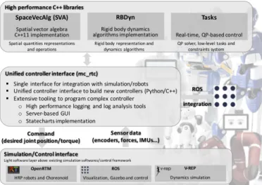
Fig. 7: Control architecture of HRP-4.
Fig. 7 illustrates the main components of the task specifica-tion and control architecture used for the control of the HRP-4 humanoid robot, using the technological bricks described in section III. This architecture is already implemented on several other robots such as those of the SoftBank Robots Pepper and Nao, the HRP robots, Sawyer... and has 3 main components:
1) Low-level and high-performance C++ libraries for robotic experts;
2) A unified controller interface mc_rtc: the control framework to facilitate the development of controllers and the integration of new robots;
3) Simulation/control interfaces that are “glue-layers” be-tween mc_rtc and simulation e.g. V-REP or Chore-onoid, or robot-hardware interface.
The mc_rtc framework is written in C++, but allows writing any robot controller in either C++ or Python. Our low-level libraries are mainly concerned with the mathematical and numerical aspects of the control, i.e. computing all the required matrices and vectors correctly in a timely man-ner, and setting up and solving optimization problems. The mc_rtcframework brings simpler interfaces, simpler seman-tics –that are rather task-centric instead of model-centric– and a range of tools to support the development of new controllers (i.e. a new mission instantiation). This framework allows experts and non-experts to build experiments.
We implemented walking and stair climbing stabilization using mc_rtc. Stabilization, i.e. balance control, aims to correct the deviation of the floating base of the biped from its reference. With the CoM being driven only by contact wrenches (section III-B), this component consists of two main steps: 1) compute desired contact wrenches, then 2) realize these wrenches by force control. For the former, we applied PID feedback control of the DCM followed by a Quadratic Programming (QP)-based wrench distribution to each foot in contact. For the latter, we used (1) single-effector admittance control to regulate the Center of Pressure (CoP) under each foot, (2) multi-effector admittance control to regulate foot pressures in double support, and (3) CoM admittance control. The combination of these tasks realizes an overall whole-body admittance control scheme. The resulting stabilizer proved effective for both walking and climbing the factory staircase, whose step height is 18.5cm; see [26] for further details.
For walking pattern generation, we implemented MPC using the open-source copra library. Viability was enforced by a terminal DCM condition at the end of the receding horizon, making walking trajectories two-step capturable. Phase tim-ings were decided based on the scenario: 1.4/0.2s for stair climbing, 0.7/0.1s for sagittal walking, and 0.8/0.2s for lateral stepping. Footholds were generated by an external footstep planner connecting current foot contacts to a world target provided by SLAM or the human operator. HRP-4 was able to lift itself up on its left leg but not on its right one due to a mechanical limitation issue. We consequently selected footsteps to use only the left leg for lifting phases [26].
All the tasks are programmed using mc_rtc statecharts. States are first programmed in C++ or Python classes, then further states can be defined by specializing the configuration of an existing state. For example, a generically programmed state allows to define a set of tasks to perform until some completion criteria are reached for each of the tasks. The default behaviour of this state is to add no tasks. However, a state can be configured to add a task on a given end-effector, and then define other states based upon this one with different targets for the end-effector. Transitions are programmed by specifying a state, its output, and the next state. Orthogonal states and nested state machines are simply implemented as generic states. The walking operations are programmed using statecharts and hence, walking and manipulation phases can be seamlessly integrated into a single controller. Walking
stabilization can be enforced during manipulation by using orthogonal states.
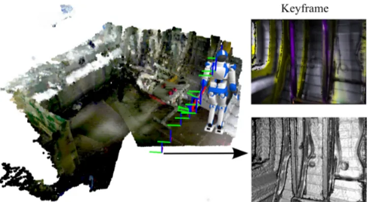
Fig. 8: View of the 3D pointcloud and keyframe graph used by HRP-4 during the demo. Right top: an image with semantic class overlay. Right bottom: fused 3D depth map.
SLAM technology was used to walk to pre-determined walking targets (stairs, bracket table, bracket assembly) with sub-centimeter precision. A keyframe-graph map of the mockup is first generated by teleoperating the robot to walk within its intended workspace. While walking, the robot ac-tively looks at areas that maximize pose tracking performance (well-textured surfaces, complex geometry). To ensure best accuracy, walking targets are saved locally as the pose of the camera w.r.t its nearest keyframe. The map thus generated is then used online to localize the robot. First, relocalization is achieved by comparing live images from the camera with recorded keyframes, providing the initial pose of the robot camera. Its relative transformation w.r.t. the recorded targets can then be easily computed through the keyframe-graph. Due to inaccuracies in the keyframe-graph (arising from camera-calibration, pose-tracking drift while building the map, etc.), the accuracy of this transformation depends, amongst other factors, on the distance between the robot and its target (typically within a 5-10cm range). As the robot gets closer to its target, fewer keyframes are considered and accuracy increases. The final accuracy near the workspace target only depends on the local tracking error to the nearest keyframes. This camera-to-target transformation is finally converted into relative walking targets by forward kinematics.
Since our footstep planner is not online, walking to a target was decomposed in sub-plans. First, the robot walks towards a waypoint close to its intended target. Then, local adjustement stepsare generated and executed based on the camera-to-target error. This process is repeated until the error converges below a desired threshold (< 0.5cm for stairs). With this method, the robot successfully and robustly reached each of its workspace targets, starting from an initially unknown position, without the use of any specific or custom markers, see Fig. 8.
The first task HRP-4 performed after climbing the stairs and entering the working area of the A350 mock-up is to grasp the bracket. This operation is programmed as follows, see Fig. 9:
1) position the left gripper above the bracket feeder; 2) trigger the tracking of the gripper and the feeder by
Fig. 9: QP tasks used during bracket grasping by HRP-4.
3) trigger the visual-servoing [21] to align the gripper above the bracket (3cm) avoiding occlusions;
4) (without visual servoing) rotate the gripper, then lower it until a contact is sensed, then move slightly upward and grasp and take the bracket;
5) prepare for locomotion toward the fuselage.
This describes only the normal mode of operation (i.e. excluding failure recovery programmed in the statechart). For example, if the tracking of either the gripper or the feeder is lost, the visual-servoing task is put on hold until tracking is recovered or a decision is made to resume the manipulation. The manipulation also involves two parallel behaviours: stabi-lization described previously, and gaze control that ensures that HRP-4 continuously looks at the gripper during the operations. After grasping the bracket, HRP-4 walks toward the fuselage using SLAM to perform the bracket assembly task that is programmed as follows:
1) trigger the environment detection and tracking by ViSP; 2) create contact between the right gripper and the A350 structure beam and keep a minimum pressure of 5 N; 3) using ViSP, the gripper is controlled to reach the fuselage
at the desired location of the bracket;
4) glue the bracket applying 10N along the surface normal; 5) resume the force to near-zero, then release the bracket; 6) remove the right hand contact;
7) Step away from the frame and come to a safe position w.r.t. the tool table (using SLAM);
The final operation showcases the embedded whole-body capacitive sensing technology. We implemented a human-presence awareness contactless-compliance, which allows HRP-4 to escape human closeness, avoiding contact. The safety repulsive field is defined from the detection range of the electrodes. A joint has a range of motion between an initial position and its lower or upper articular limit. The CoM task has a range between its initial position and a safe lower position along world z-axis. In this demo we achieved a simple electrodes to joint or CoM surjective mapping. The relation between an Electrode Capacitance Measurement (ECM) value
and the computed target for the desired task is expressed as a percentage in their respective range. Fig. 10 illustrates the relationship between the sensors reading on the head electrodes –numbered ID 1 to 4, and the CoM height.
Fig. 10: Interaction between electrode (left-hand y-axis) and CoM height (right-hand y-axis) shows how the robot reacts preemptively to contact. The user did not physically touch the robot (electrode values approach but do not hit zero).
A configuration file describes a set of behaviours as {Name, Electrodes, Affect, Target}, where Name is the behaviour name, Electrodes is a list of electrodes, Affect is either a joint name or a task name (i.e. HRP-4 joint name or CoM) and Target is either lower-limit or upper-limit (i.e. an ECM equal to 0 means the task target is equal to Target value, and an ECM equal to maximum value means Affect is in initial position). As explicitly describing every relation is too long (24 electrodes and 7 targets for 13 behaviours), they are compressed as follows: Head electrodes modify CoM target along world z-axis target; shoulder electrodes modify chest yaw joint target; back electrodes modify chest pitch joint target to lean frontward whereas torso electrodes control backward leaning; upper-arm electrodes affect shoulder roll and pitch. B. Demonstrator with the TORO humanoid robot
TORO performed a complete demonstration for placing a bracket. In all phases of the presented demo the robot is fully torque controlled. We used a passivity based whole-body controller [7], [8] for the manipulation tasks, and combined this controller with our DCM framework for walking [11]. The whole demonstration was executed in a fully autonomous way without any intervention by a human operator.
For navigating in the Airbus mockup the robot uses land-marks, and the motion between two different landmarks defines a substage of step planning. Once the subgoal for a walking motion is achieved, the next stage is planned and executed. This approach allows the verification of self-localization of the robot within the mockup, to guarantee that the robot achieves the posture required to successfully fulfill the intended task, with an overall deviation lower than 2 cm
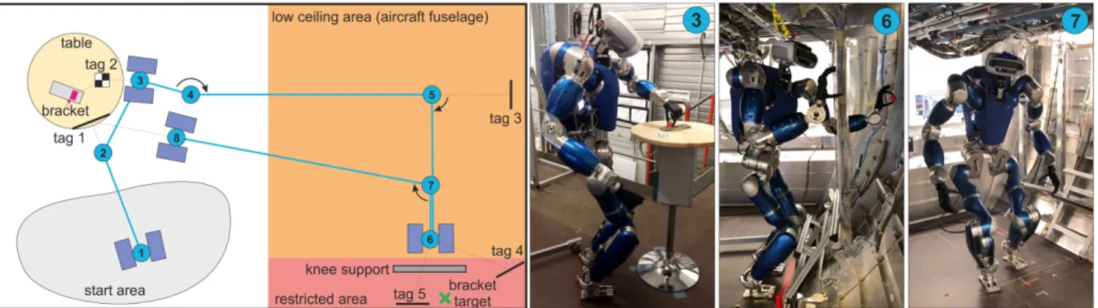
Fig. 11: Overview of the demonstration performed by the torque controlled robot TORO.
with respect to the required position for placing the bracket. The walking motion is executed in different postures:
• normal, upright walking, with knees slightly bent
• crouched walking, required to move within the mockup and prevent collisions with the head due to the low height of the ceiling.
Based on the DCM formulation, CoM trajectories (position, velocity and acceleration) are generated using a piecewise interpolation over a sequence of waypoints [27], while the trajectories of the feet are generated as fifth-order polynomials. These reference trajectories are tracked by a passivity-based whole-body controller.
Recent developments have allowed TORO to walk upstairs using toe-off motions to increase the kinematic workspace of the leg and therefore allowing the robot to negotiate stairs with step height of 18 cm and step length of 28 cm [28]. However, the demonstrator did not include entering and exiting the area using the stairs.
Figure 11 gives an overview of the complete operation. In the following, we briefly describe each of the individual steps. Points 1 to 2: First, the robot localises itself with respect to the table on which the brackets are stored. Localisation is performed using AprilTags. The robot approaches the table and moves into a configuration such that the bracket holder is well within the dexterous workspace of the left arm.
Point 3:TORO finds the bracket holder exact position on the table and picks up one of the brackets using a predefined grasp. Point 4: the robot backs away from the table and turns into the direction of the mockup. Due to the low height of the ceiling the robot cannot walk fully upright within the mockup. Therefore it changes its whole-body posture into a crouched configuration before entering the aircraft. In this configuration the robot lowers its CoM by additional 7 cm and bends its upper body forward 20°, resulting in a total height of about 1.6 m (the normal walking height of the robot is 1.75 m). Points 4 to 6: The robot then walks towards tag 3 into the mockup and localises itself. When it is close enough it turns right and localises the final target location for the bracket. It further approaches the target location to a point from which it can place the bracket in a multi-contact configuration. Point 6: The operation of placing the bracket can be achieved using three different multi-contact configurations (see Fig. 2):
• Standing posture, with one arm grasping a vertical strut.
This is the more suitable posture for executing the task, and the robot uses the additional support on the hand to extend the reachability while guaranteeing balance.
• Standing posture with knee support, where both knees rest on a horizontal beam. This posture is particularly interesting, because it requires to control precisely the internal forces in the robot. This is an over-constrained configuration since the contact forces at the feet and the contact forces at the knees cannot be controlled fully independently.
• Kneeling posture (no foot contact)
All postures exploit the combination of the passivity-based controller with a hierarchical whole-body control [8], which allows prioritisation of the multiple tasks that the robot should execute, including support generation as first priority, and CoM plus manipulation task as second priority. In the presented demo, the robot utilises the standing posture with knee support. In this way, the robot can lean forward to place the bracket in a location that would not be reachable with only feet support. The passivity-based balancer developed for TORO distin-guishes between end-effectors used for balancing (assuming that they are in rigid contact with the environment) and end-effectors used for accomplishing additional interaction tasks. A compliant reaction force acting on the CoM is then distributed to the end-effectors used for balancing, while taking the desired control forces of the other end-effectors into account. The algorithm requires the solution of an optimisation problem taking into account constraints for unilaterality, friction, and position of the CoP [7], [9].
Points 7 to 8: After the bracket is successfully placed, the robot retreats several steps, looks for the table holding the brackets (which is used for self-localisation to find its way out of the mockup) and starts walking towards it.
Point 8: Finally, the robot returns from the mockup and switches back to the upright posture. Then, the robot can restart the whole procedure in order to place the next bracket. In order to demonstrate the robustness of the torque based walking using the DCM framework, we additionally demon-strate a short walk over uneven terrain (see Fig. 12). This sim-ulates possible ground irregularities like cover plates, cables, or other debris lying on the floor.
Fig. 12: The combination of the torque-based whole-body con-trol framework with the DCM-based gait stabilization allows for walking over rough terrain. The lower part shows the COM, DCM, and VRP trajectories. The increased oscillations around t = 10s are related to edge contacts on the debris.
Fig. 13: Control architecture of TORO.
Figure 13 illustrates the control architecture of TORO. All control approaches used in this demonstration benefit from the joint torque control available in the robot. While the low level joint control runs at a rate of 3 kHz in local processors, the whole-body controllers run in a centralized realtime computer at a rate of 1 kHz. We use Linux with the PREEMPT RT patch as the RT operating system. Additional details on the hardware and software of TORO can be found in [29].
V. DISCUSSION AND RECOMMENDATIONS
The previously described experiment was prepared in-situ during two weeks. On the date of the final demonstration (corresponding to the final evaluation of the project) the experiment was performed two times with secured ropes. The reliability of the performance allowed running two other demonstrations without security harness/ropes, as shown in the accompanying video. We aimed at a last one with HRP-4 but unfortunately, a software bug made it fall on its right side. Some right arm parts of the cover appeared damaged. The robot was fully repaired in-lab. Since the mechanical piece
linking the forearm to the arm was weak it deformed and most of the shock was absorbed by it: none of the actuators, the gears nor the capacitive sensing were damaged! This raises an interesting observation for designing more robust hardware. So far, the first limiting factor of our developments is the weakness of our platforms. Securing the humanoid robots acts as a high damping to research and developments efforts. Therefore, we advice that any upcoming humanoid platform shall be designed from the very beginning to fall repeatedly without hardware damage. Working with the described hu-manoids without any perspective of hardware improvement in the course of the project put a lot of constraints on what could be potentially achieved. We designed a new gripper for HRP-4 for bracket and buttons grasping, but that gripper could not be used for contact supporting robot motions. TORO uses a prosthetics hand as gripper.
Almost all limitations are due mainly to (i) non-proprietary technologies, (ii) limited robustness in the perception, (iii) no recovery strategies were implemented because of the sub-sequent engineering efforts. The consortium was struggling in adapting perception, control and planning to overcome these limitations. Full assessments and improving performance require extensive testing that are difficult to achieve with humanoids. Bridging the theory to practice is clearly another theory: there are still too many “magic numbers” to set, so it is worth spending research in lowering ad-hoc tunings.
From the experiences we conducted, the range of motion (limited because of the wiring) is an important issue in cluttered/confined environments. In fact, extra-redundancy – with the inconvenience of extra-costs– is also needed in some places. All our robots have hard covers, which is not robust to secure contact formation. Intrinsic or active joint compliance is not enough to secure a sustained contact (as the structure of the airplane is also rigid), soft covers are a better fit that come with many other advantages. Safety is still an open issue, it is worth dedicating efforts to extend the cobots safety requirements EN ISO 10218 standard Parts 1 and 2, and the ISO/TS 15066 specification, to include humanoid robots. As for manipulation capabilities, we may consider interchangeable tools instead of a single sophisticated gripper. Concerning the energy and power supply, Airbus allows (they actually have) power supply cables nearly everywhere; therefore the humanoid robots can be embedded with short time autonomy as far as they have the capability to autonomously plug and unplug themselves to the available power supply cables. There is still much to do in impact absorption technology for safe falling and in falling detection and recovery strategies that should be highly considered. There are also many other recommendations that we keep for the innovation stage.
There are encouraging results as for the software architec-ture (the HRP-4 is fully open-source code). We were able to achieve, with exactly the same controller, the same task templates and the same methodology, two other use-cases that we do not report here, since they are part of another project and they were not demonstrated in-situ: torqueing in multi-contact dynamic motion and circuit breaker operations in [3], but without the markers, see Fig. 14. This is very promising as our new objective now is to reach human-speed performance
Fig. 14: Narrow access in multi-contact and fast dynamic torqueing handling four contacts with HRP-2Kai. (left). Circuit breaker checking combining multi-sensory task-space control with HRP-4, achieved without visual markers (right).
and reliability in all these tasks and other ones to come. Any further continuation of this project is subject to the ultimate question by Airbus –but also by any other large scale manufacturing that show interest in this technology (and we have already a few): who will build and commercialise humanoid robots for manufacturing? That is to say, certified robots, robust enough to work continuously with near human-speed performance with time-cycle and reliability comparable to current industrial robots. The few big companies that are capable, do not see a substantial business w.r.t their current or other products; whereas medium or small size companies are certainly not large enough for such a challenge, knowing that it does not suffice to provide the hardware, but also an integrated automation turnkey solution.
REFERENCES
[1] K. Bouyarmane, S. Caron, A. Escande, and A. Kheddar, Multi-contact motion planning and Control. Springer Netherlands, 2018, pp. 1763– 1804.
[2] S. Brossette, A. Escande, and A. Kheddar, “Multi-contact postures computation on manifolds,” IEEE Transactions on Robotics, vol. 34, no. 5, pp. 1252–1265, October 2018.
[3] A. Bolotnikova, K. Chappellet, A. Paolillo, A. Escande, G. Anbarjafari, A. Suarez-Roos, P. Rabat´e, and A. Kheddar, “A circuit-breaker use-case operated by a humanoid in aircraft manufacturing,” in IEEE Conference on Automation Science and Engineering, Xi’an, China, 20-23 August 2017, pp. 15–22.
[4] G. Mesesan, J. Englsberger, B. Henze, and C. Ott, “Dynamic multi-contact transitions for humanoid robots using divergent component of motion,” in 2018 IEEE International Conference on Robotics and Automation, Singapore, Singapore, May 2017, pp. 4108–4115. [5] K. Bouyarmane, K. Chappellet, J. Vaillant, and A. Kheddar, “Quadratic
programming for multirobot and task-space force control,” IEEE Trans-actions on Robotics, vol. 35, no. 1, pp. 64–77, February 2019. [6] H. Audren and A. Kheddar, “3D robust stability polyhedron in
multi-contact,” IEEE Transactions on Robotics, vol. 34, no. 2, pp. 388–403, April 2018.
[7] B. Henze, M. A. Roa, and C. Ott, “Passivity-based whole-body balancing for torque-controlled humanoid robots in multi-contact scenarios,” The International Journal of Robotics Research, vol. 35, no. 2, pp. 1522 – 1543, 2016.
[8] B. Henze, A. Dietrich, M. A. Roa, and C. Ott, “Multi-contact balancing of humanoid robots in confined spaces: Utilizing knee contacts,” in IEEE International Conference on Intelligent Robots and Systems, September 2017, pp. 679 – 704.
[9] C. Ott and S.-H. Hyon, Torque-Based Balancing. Springer Netherlands, 2016, pp. 1–26.
[10] P.-B. Wieber, R. Tedrake, and S. Kuindersma, Modeling and Control of Legged Robots. Springer, 2016, pp. 1203–1234.
[11] J. Englsberger, C. Ott, and A. Albu-Sch¨affer, “Three-dimensional bipedal walking control based on divergent component of motion,” IEEE Transactions on Robotics, vol. 31, no. 2, pp. 355–368, April 2015. [12] N. Boh´orquez, A. Sherikov, D. Dimitrov, and P.-B. Wieber, “Safe
navigation strategies for a biped robot walking in a crowd,” in IEEE-RAS International Conference on Humanoid Robots, November 2016, pp. 379–386.
[13] N. Scianca, M. Cognetti, D. De Simone, L. Lanari, and G. Oriolo, “Intrinsically stable MPC for humanoid gait generation,” in IEEE-RAS International Conference on Humanoid Robots, 2016, pp. 601–606. [14] D. De Simone, N. Scianca, P. Ferrari, L. Lanari, and G. Oriolo,
“Mpc-based humanoid pursuit-evasion in the presence of obstacles,” in IEEE/RSJ International Conference on Intelligent Robots and Systems, September 2017, pp. 5245–5250.
[15] A. Pajon and P.-B. Wieber, “Safe 3D bipedal walking through linear MPC with 3D capturability,” in IEEE International Conference on Robotics and Automation, May 2019.
[16] M. Meilland and A. I. Comport, “On unifying key-frame and voxel-based dense visual slam at large scales,” in IEEE/RSJ International Conference on Intelligent Robots and Systems, Tokyo, Japan, November 2013, pp. 3677–3683.
[17] F. I. Ireta Munoz and A. I. Comport, “Point-to-hyperplane ICP: fusing different metric measurements for pose estimation,” Advanced Robotics, vol. 32, no. 4, pp. 161–175, 2018.
[18] H. Mah´e, D. Marraud, and A. I. Comport, “Real-time rgb-d semantic keyframe slam based on image segmentation learning from industrial cad models,” in submitted to IROS: International Conference on Intelligent Robots and Systems, 2019.
[19] E. Marchand, F. Spindler, and F. Chaumette, “Visp for visual servoing: a generic software platform with a wide class of robot control skills,” IEEE Robotics and Automation Magazine, vol. 12, no. 4, pp. 40–52, December 2005. [Online]. Available: https://visp.inria.fr
[20] S. Trinh, F. Spindler, E. Marchand, and F. Chaumette, “A modular framework for model-based visual tracking using edge, texture and depth features,” in IEEE/RSJ Int. Conf. on Intelligent Robots and Systems, Nov 2018, pp. 89–96.
[21] D. J. Agravante, G. Claudio, F. Spindler, and F. Chaumette, “Visual servoing in an optimization framework for the whole-body control of humanoid robots,” IEEE Robotics and Automation Letters, vol. 2, no. 2, pp. 608–615, April 2017.
[22] N. Scianca, L. Lanari, and G. Oriolo, “Deliverable D3.3: Final safety guidelines and strategies,” 2019. [Online]. Available: http: //comanoid.cnrs.fr/publications
[23] V. Samy and A. Kheddar, “Falls control using posture reshaping and active compliance,” in IEEE-RAS 15th International Conference on Humanoid Robots, Nov 2015, pp. 908–913.
[24] T. Mattioli and M. Vendittelli, “Interaction force reconstruction for humanoid robots,” IEEE Robotics and Automation Letters, vol. 2, no. 1, pp. 282–289, 2017.
[25] G. Garofalo, N. Mansfeld, J. Jankowski, and C. Ott, “Sliding mode momentum observers for estimation of external torques and joint accel-eration,” in IEEE Int. Conf. on Robotics and Automation, May 2019. [26] S. Caron, A. Kheddar, and O. Tempier, “Stair Climbing Stabilization of
the HRP-4 Humanoid Robot using Whole-body Admittance Control,” in IEEE International Conference on Robotics and Automation, May 2019. [27] G. Mesesan, J. Englsberger, C. Ott, and A. Albu-Sch¨affer, “Convex prop-erties of center-of-mass trajectories for locomotion based on divergent component of motion,” IEEE Robotics and Automation Letters, vol. 3, no. 4, pp. 3449–3456, 2018.
[28] B. Henze, M. A. Roa, A. Werner, A. Dietrich, C. Ott, and A. Albu-Sch¨affer, “Analysis of human-like behaviors in a humanoid robot: Quasi-static balancing using toe-off motion and stretched knees,” in IEEE Int. Conf. on Robotics and Automation, May 2019.
[29] C. Ott, M. A. Roa, F. Schmidt, W. Friedl, J. Englsberger, R. Burger, A. Werner, A. Dietrich, D. Leidner, B. Henze, O. Eiberger, A. Beyer, B. B¨auml, C. Borst, and A. Albu-Sch¨affer, Mechanisms and Design of DLR Humanoid Robots. Springer Netherlands, 2016, pp. 1–26.