DOE/ET-51013-87
ALCATOR DCT PROPOSAL
B. B:.ackwell, M. Greenwald, D. Gwinn, B. Lipschultz, E. Marmar, D. B. Montgomery, R. Parker, P. Politzer,
M. Porkolab, J. Schultz, S. Wolfe
Plasma Fusion Center
Massachusetts Institute of Technology Cambridge, MA 02139
October 1983
This work was supported by the U.S. Department of Energy Contract
No. DE-AC02-78ET51013. Reproduction, translation, publication, use
and disposal, in whole or in part by or for the United Stated
govern-ment is permitted.
MASSACHUSETTS INSTITUTE OF TECHNOLOGY PLASMA FUSION CENTER
ALCATOR DCT PROPOSAL
OCTOBER, 1983
Submitted to OFFICE OF FUSION ENERGY
U. S. DEPARTMENT OF ENERGY
WASHINGTON, D. C. 20545
Ronald C. Davidson
Director, Plaama Fusion Center
Ronald R. Parker PFC Associate Director for
Confinemert Experiments
George H. Dummer Director
Office of Sponsored Programs
D. Bruce Montgomery PFC Associate Director for
ADVANCE COPY
ALCATOR DCT PROPOSAL
B. Blackwell, M. Greenwald, D. Gwinn, B. Lipschultz, E. Marmar, B. Montgomery, R. Parker, P.- Politzer, M. Porkolab, J. Schultz, S. Wolfe
Plasma Fusion Center
Massachusetts Institute of Technology Cambridge, MA 02139
Acknowledgements
Many people have contributed to the development of the Alcator DCT
concept and the preparation of this document. Ths following specific
contributions are gratefully acknowledged: P. Bonoli and B. Lloyd have provided material in support of LH heating and current drive plans; D. Blackfield and B. Koester have contributed to the ICRF heating concept;
D. Pappas has done computations concerning requirements for neutron shielding; R. Granetz and P. Pribyl have aided in MHD equilibrium and
stability computations; M. Besen, H. Becker, E. Bobrov and R. Thome have
carried out engineering analysis and made useful contributions to the design; D. Griffin and J. Rose have provided material for RF and AC power
systems design; N. Diatchenko and A. Chernomordik have skillfully produced
most of the engineering drawings and technical illustrations, respec-tively.
The highly competent, professional and tireless efforts of L.
Pfeifer, B. Ogar, L. McKnight, A. Kotsopoulos, D. Marble and L. Funari
TABLE OF CONTENTS
1. INTRODUCTION
1.*1. Introduction...****
~
* e s...* ... 1-11.1.1. Background... 1-1. 1.1.2. Alcator DCT
Objectives...e...
1-31.1.2.1. Plasma Physics Issues... 1-6 1.1.2.2. Plasma Engineering Issues... 1-9 1.1.2.3. Long Pulse Tokamak Technology Issues... 1-13 1.2. Alcator DCT Description... . ... ... 1-16 1.2.1. General Considerations... ... 1-16 1.2.2. Alcator DCT Specifications and Expected Parameters 1-17 1.2.2.1. Plasma Geometry... 1-19 1.2.2.2. Magnetic Field Strength... 1-19 1.2.2.3. Magnetics Technology ... 1-20 1.2.2.4. RF
Systems...
1-21 1.2.2.5. Plasma Parameters... 1-22 1.3. Programmatic Roe...1-231.3.1. Role Within the Toroidal Confinement Program Plan 1-23 1.3.2. Relationship
to
TFCD...
1-28 1.3.3. Relationship to Other Experiments... 1-291.3.3.1. Existing Copper Devices and
their Upgrades ... 1-29 1.3.3.2. Comparison to Tore Supra... 1-32
2. PLASMA PHYSICS CONSIDERATIONS
2.1. Introduction... 2.2. Plasma Regimes...
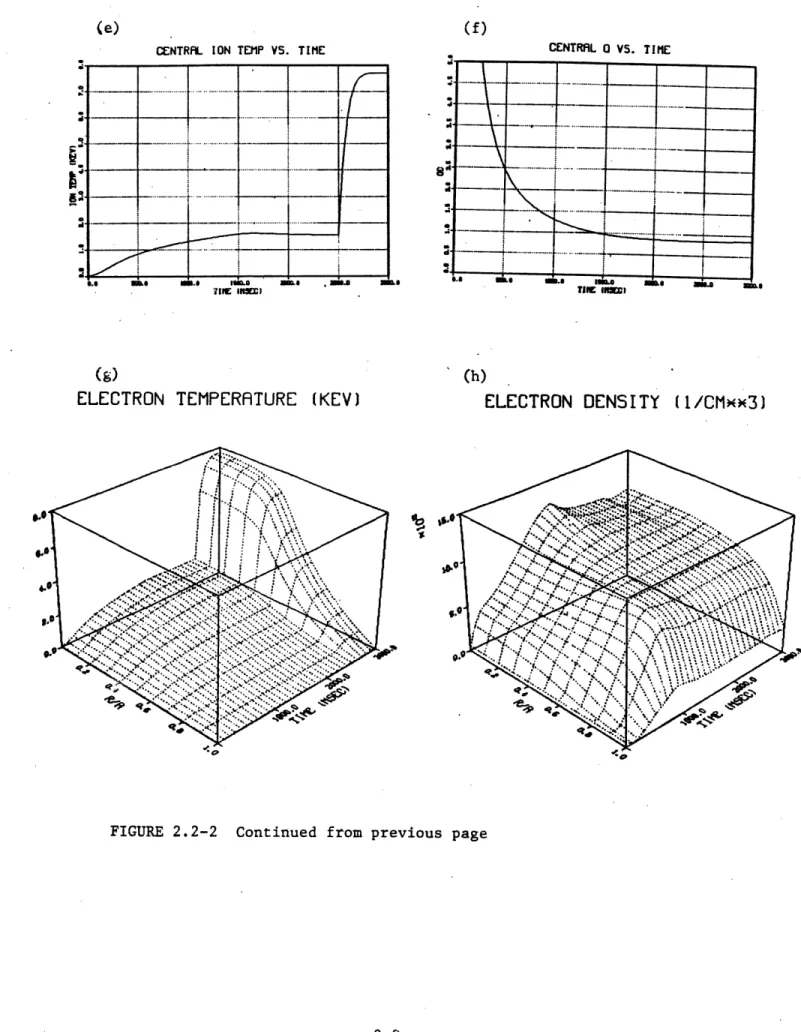
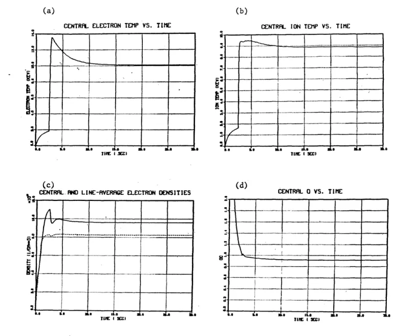
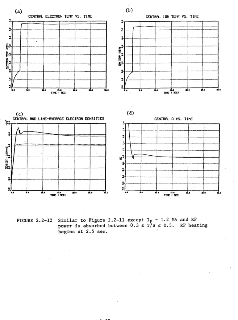
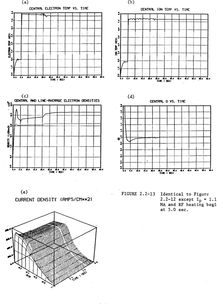
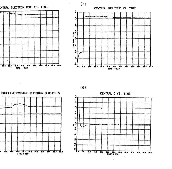
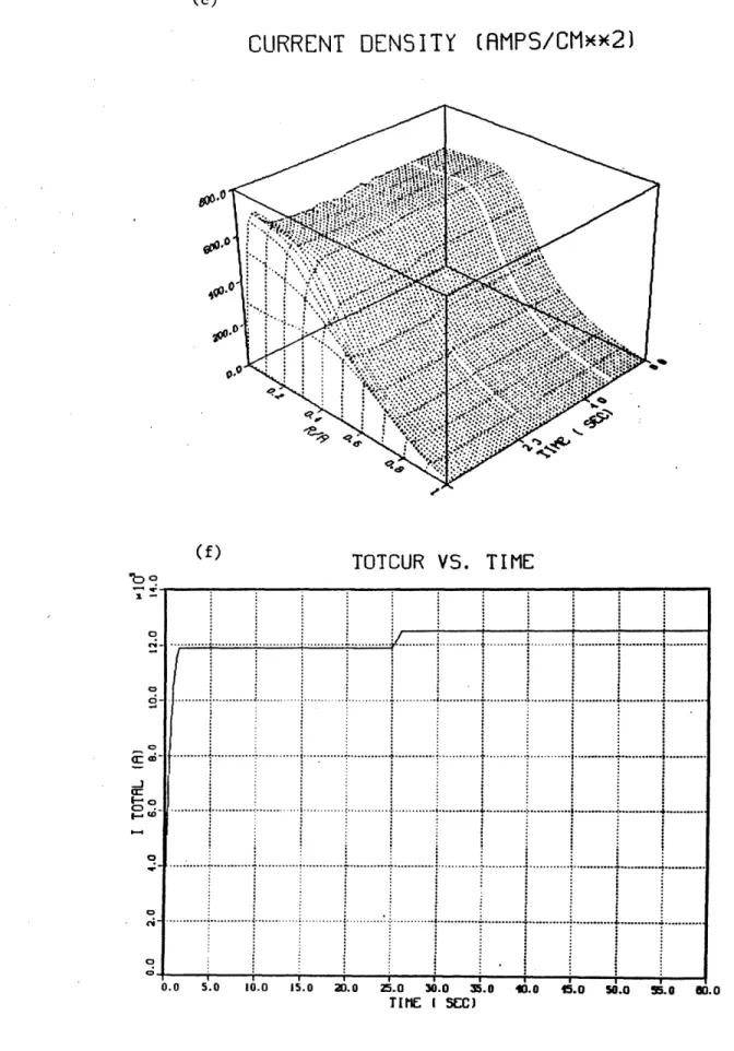
2.2.1. Introduction... 2.2.2. Ohmic Plasma Parameters... 2.2.3. High Power Heating Simulations... 2.2.4. Shaped Plasmas... 2.2.5. Time Evolution...
2.2.6.
Summary... 2.3. MHD Configurations... 2.3.1. General Considerations... 2.3.2. Divertor Configurations... 2.3.3. The Alcator DCT Divertor... 2.3.4. Plasma Shaping.. ...2.3.5. Beta Dependent Equilibrium Effect 2.3.6. Stability Limits... 2.3.7. The Vertical (n=O) Instability... 2.4. RF Current
Drive...
2.4.1. Introduction... 2.4.2. Frequency Selection..."... 2.4.3. Accessibility... 2.4.4. Brambilla Spectrum... 2.4.5. Current Drive Efficiency... 2*4.6. Ray
Tracing...
.2.4.7. Code Simulations... 2.5. RF Heating...
2.5.1. Lower Hybrid Heating...
... .. 0 .. .. & .. ... ... .. * .. ... .... .. 0 . .. . .. 0 . .. . .. 0 . .. . .. 0 . .. . .. 0 . .. . .. 0 . .. . .. a . .. . .. 0 . .. . .. 0 . .. . .. 0 . .. . .. 0 . .. . .. 0 . .. . .. 0 . .. . .. 0 . .. . .. 0 . .. . .. 0 . .. . .. 0 . .. . .. 0 . .. . .. 0 . .. . .. 0 . .. . .2-1 2-2 2-2 2-4 2-10 2-18 2-24 2-30 2-37 2-37 2-38 2-41 2-44 2-44 2-49 2-51 2-53 2-53 2-54 2-58 2-63 2-65 2-67 2-72 2-83 ... 0 ... * ... 0 ... 2-83
2.5.2. ICRF Heating Physics...*... 2-86 2.5.2.1. Introduction...* 2-86
2.5.2.2. The Dispersion Relation... 2-86
2.5.2.3. Predictions of a 1-D Four Wave Slab
Model...00*...
2-882.5.2.4. Predictions of a 2-D Fokker-Planck Code.. 2-92 2.5.2.5. Summary of ICRF Physics... 2-94
3. PLASMA ENGINEERING
3.1. Introduction...*..**...o**O*..000.0000.0 3-1
3.2. Pellet Injection... 3-2
3.2.1. Introduction..o.ooooooo*o eoo*o...**o.o... 3-2
3.2.2. Requirements...00... 3-3
3.3. Particle and Impurity Control Techniques... 3-5
3.3.1.
Introduction...00.0.0000... 3-53.3.2. Pumped Limiter... 000.0000000000000000000000 3-6
3.3.3. Internal Poloidal Divertor... 3-8
3.3.4. External Poloidal Di . . . 3-10
3.3.5. Heat Deposition Calculation... ... 3-13
3.3.6. Edge Plasma Parameters... 3-18
3.3.7. Heat Removal Components... 3-21
3.3.8. Heat Removal and Impurity Control Summary... 0 3-25
3.4. RF Systems and 3-31
3.4.1.
Lower Hybrid System ... 3-313.4.1.1. General .... 3-31
3.4.1.2. Lower Hybrid Coupoer... 3-33
3.4.2. The Alcator DCT ICRF System...y.te 3-40
3.4.3.3. Antenna.
...
. 3.4.2.4. Transmission System... 3.4.2.5. Advanced Coupler Design... 4. ALCATOR DCT POINT DESIGN4.1. Introduction...*...e..e.**..*
4.2. Overall Machine Description...
4.3. Magnetic System Concept Selection... 4.3.1. Toroidal Field Coils... 4.3.1.1. Conductor Choice... .
4.3.1.2. Winding Pack Design... 4.3.1.3. Structural Approach and Stress
Analysis...
4.3.1.4. Protection... 4.3.2. Poloidal Field System...
4.3.2.1. Conductor Selection...
4.3.2.2. Current and Voltage Level Selections.. 4.3.2.3. PF Coil Loads and Structural Approach. 4.3.3. Cryogenic Considerations... .... ... .
4.3.3.1. Design Approaches... 4.3.3.2. Cryogenic Refrigeration System
and Loss Inventory... 5. VACUUM VESSEL, COOLING SYSTEM, and VACUUM PUMPING
5.1. Vacuum Vessel....
...
5.2. Vessel Cooling System... .. ... .... .5.3. Vessel Vacuum Pumping System... 6. ALCATOR DCT DIAGNOSTICS
6.1.
Introduction...o...
6.2. Fully Developed Diagnostic Systems...e...
4-51 4-53 4-56 4-56 ... 4-58 5-1 5-10 5-14 6-1 6-1 3-44 3-46 3-46 4-1 4-2 4-11 4-11 4-11 4-16 4-23 4-36 4-38 ... 4-44
...
...
6.3. 6.4. 6.5. 7. DATA 7.1. 7.2. Automa 8. FACILITIES 8.1. Siting 8.1.1. 8.1.2. 8.1.3. 8.1.4. 8.2. Power 8.2.1. 8-.2.2. 8.2.3.
ted Control System...
and Building Layout...
Overall Site Description... ... ... .
Shielding Requirements of the Experimental Cell... Experimental Cell and Power Equipment Area
Description...
SupportArs...
PrimePor...
Magnet Power Supplies...
RF Power
System...
8.2.3.1. Lower HybridSystem...
8 . 2. 3. 2. ICRF...
Diagnostic Systems in Development... Special Steady-State Diagnostics Issues... Summary. .0 . . . .. . . . .. . ..
ACQUISITION and CONTROL
Data H0d0ng . .. .. . .. .. . .. .. . .. .. .
7.1.1. System Description... 7.1.2. Data Acquisition Hardware - CAMAC...
7.1.3. Computers...
7.1.4. Back-End Network...
7.1.5. Local Area Network... 7.1.6. Data Display System... 7.1.7. Data System Software...
0~~~~~~~ .0 00a ... 6-9 6-12 6-13 7-1 7-2 7-4 7-5 7-6 7-7 7-8 7-9 7-10 8-1 8-1 8-3 8-5 8-6 8-6 8-6 8-9 8-12 8-12 8-15
9. ALCATOR DCT RESEARCH and DEVELOPMENT ACTIVITIES 10. COST, SCHEDULE and PROJECT MANAGEMENT
10.1. Co t . . . . 10-1
10.1.1. Costing Basis for Fabrication and Purchased
Components ... 10-1
10.1.1.1. Torodial Field Coils and Intercoil
Structure... 10-4 10.1.1.2. Poloidal Field Coils and PF
Cryostats...o... 10-6 10.1.1.3. Magnet Vacuum Cryostat... 10-8 10.1.1.4. Refrigeration... 10-8 10.1.1.5. Vacuum Chamber Torus and Vacuum
Pumping...0 10-9 10.1.1.6. Collector Plates and Heat Shields... 10-10 10.1.1.7. Site Modifications... 10-11 10.1.1.8. Power andControl... 10-12 10.1.1.9. RF Modifications... 10-13 10.1.1.10. Alcator DCT Research and Development
Activities...,... 10-15 10.1.2. Composite Labor Costs for Engineering,
Installation, and Project Management... 10-16 10.2. Scheduleo... 10-19 10.3. Funding Profiles... 10-22 10.4. Project Management... ... 10-25 10.4.1. Management
Plan...
10-25 10.4.2. Project Organization... 10-28APPENDICES
A. DESCRIPTION OF THE LOWER HYBRID CURRENT DRIVE CODE B. HEAT LOAD ANALYSIS
B.1. Thermal Hydraulics of the Collector Plate...B-i B.2. Disruption Characteristics and Lifetime Analysis... B-4 C. EDDY CURRENT EFFECTS
C.1. Disruption Induced Eddy Currents... C-1 C.2. Startup Induced Eddy Currents... C-13 D. HIGH POWER RF INDUCED IMPURITY GENERATION IN TOKAMAK EXPERIMENTS
D.1. Introduction... . ... ... ... . . D-1
D.2. TFR... D-1
D.3. Alcator C... D-4
D.4. PLT... D-10 E. ENHANCEMENTS
E.1. RF Systems... .. o... E-1
E.1.1. Enhanced Lower Hybrid Current Drive System... E-1
E.1.2. Enhanced ICRF Systems... E-3 E.1.3. ECRH
Option..o.o..*o...eo.oo*.o.o..
o*.*... E-3 E.2. Beta-Enhancement with Extreme Shaping... E-4 E.3. Internal Coils for Divertors and Shaping... E-7 F. REACTOR RELEVANCEF.1. Magnetic Fieldo...o... F-2 F.2. Aspect Ratio... ... F-3 F .3. Beta...**o.. ... F-5 F.4. Long Pulse Capability... F-7 F.5. Lower Hybrid Current Drive... ... F-7
CHAPTER 1 INTRODUCTION 1.1. Introduction
1.1.1. Background
The last decade of tokamak research has seen continuous and often
remarkable progress in the approach of tokamak plasmas to the reactor
regime. For example, ntE values in excess of those required for breakeven have been achieved in Alcator C and FT (Frascati tokamak), temperatures
in excess of the minimum necessary for ignition have been attained on PLT and PDX, and s-values in excess of the minimum required for practical
de-sign of a tokamak reactor have been achieved in D-III. Preliminary results
from TFTR suggest that the confinement will be adequate to allow the goal of scientific breakeven to be achieved in the middle of this decade.
Taken together, these results imply that the tokamak is nearing the end of the scientific feasibility stage of its evolution toward the goal
of a practical fusion reactor. According to DOE policy, the concept is thus entering a product definition phase, in which it must be estab-lished that the tokamak can result in an attractive, practical fusion
reactor. While further improvement in confinement at high-s and fusion
relevant temperatures must still be demonstrated (and these are, in fact,
major goals of D-III and TFTR, respectively), the central task confronting the tokamak program is to show that certain issues related to the
develop-ment of the tokamak to a practical reactor can be resolved.
Many of these issues can be classified as having to do with extension
of the pulse length. Owing to considerations of thermal fatigue and
of pulse of a tokamak reactor is about 104 s. In contrast, all currently operating tokamak experiments have pulses which last only 1 s or less
under conditions of reactor-relevant density. It is interesting to note
that the issue of extension of pulse length has been recognized within the national tokamak program at least since the late 1970's.
Neverthe-less, during the past five years there has been no significant increase
of the pulse length in tokamak experiments in either the U.S. or the international community. This is so even though the transformer volt-seconds and the toroidal field pulse capability in many experiments are
adequate to allow pulses of several seconds. The limitation in pulse
length in present-day devices is due not only to constraints imposed by the magnetic systems but also to factors such as duration of auxiliary
heating pulse, capacity of cooling systems and lack of long-pulse impurity
control methods. Existing facilities simply do not have the capability to extend pulse length beyond original design values without extensive
(and expensive) modifications.
These considerations have motivated the proposed Alcator DCT device,
a superconducting tokamak with major radius of 2.0 m, minor radius of 0.4 m and an axial toroidal field of 7 T. Both poloidal field (PF) and toroidal field (TF) magnets are entirely superconducting and -can be operated at full performance continuously. The PF system permits plasma currents of
at least 1 MA (q = 3, circular), allows elongations of 1.4 and produces a single-null divertor configuration with external coils. The baseline auxiliary heating package provides 4 MW of CW power at lower hybrid (LH) frequency, and 5 MW of CW power in the ion cyclotron frequency range. The
LH power can be used either to heat electrons or to drive current, a fea-ture which allows the possibility of true steady-state operation. An
isometric view of the proposed Alcator DCT is presented in Figure 1.1-1. A more detailed machine description follows in Section 1.2.
Extension of the pulse length to a duration greater than 100 s in a medium-scale experiment such as the proposed Alcator DCT represents a
cru-cial step in the product definition stage of the tokamak concept.
Suc-cessful accomplishment of the mission and achievement of the objectives
will provide essential information for the tokamak engineering device and greatly enhance the potential of the pulsed tokamak as a practical reactor. Even more significant would be the attainment of a true steady-state in a tokamak operating with plasma parameters close to the reactor regime.
Several important engineering advantages accrue from steady-state
opera-tion and this concept would lead to a substantially more attractive reac-tor.
1.1.2. Alcator DCT Objectives
The major purpose of the Alcator DCT program is to demonstrate
long-pulse to steady-state operation of a tokamak with reactor level
parame-ters. In this context, "long-pulse" means in excess of 100 s, and "reactor level parameters" implies densities of about 1020 m- 3
and peak tempera-tures of at least 5 keV. In carrying out this mission, the Alcator DCT
program will make important contributions in three distinct areas: plasma
physics, plasma engineering and tokamak technology. This multi-faceted
program is in contrast to those of present-day tokamaks whose major ob-jectives are determined solely by plasma physics considerations. While
such issues are certainly important to the evolution of a tokamak pulse,
H
0
0
4) 0) Itwengineering and technology are equally important.
The Alcator DCT design is based on many concepts which have been produced by the Development and Technology Program of OFE over the past
several years. Because it is dependent on advanced technologies either developed or under development, it is more closely tied to D and T
pro-grams than any previous tokamak. This dependence could provide a new
opportunity to strengthen both programs through a joint focus on a
near-term advanced technology confinement experiment.
The breadth of the Alcator DCT program is reflected in the following set of programmatic objectives:
* Investigation and optimization of the time-evolution of high-performance tokamak discharges for pulse length well
in excess of the resistive diffusion time.
* Development of methods of shape and profile control to optimize stability and performance under steady-state
conditions.
* Development and evaluation of methods of non-inductive current drive and RF heating techniques appropriate for reactor level plasmas.
* Development of plasma edge, particle and impurity control methods required for long-pulse to steady-state operation with reactor level plasmas.
* Demonstration of fully-integrated, high-performance super-conducting toroidal field (Nb3Sn) and poloidal field (NbTi) systems.
* Development and evaluation of high heat flux and RF com-ponents appropriate for reactor applications.
The first two objectives are related mainly to plasma physics; the middle
two to plasma engineering and the last two to tokamak technology. The issues which must be addressed in achieving these objectives and the
ap-proach which has been adopted in Alcator DCT are discussed in the remain-der of this section.
1.1.2.1. Plasma Physics Issues
It is well known that a tokamak discharge cannot be considered to be
in the steady-state until the passage of a few skin times TS where tS
-PO
ya2/4. This time, which is essentially the time required for relaxation
between two equilibria, is in the range 10-100 s for plasmas with
multi-keV temperature and minor radius of the order of 1 m. In a typical tok-amak scenario, a low temperature ohmic plasma is heated by an auxiliary
heating pulse, a process which comes to thermal equilibrium on the energy
transport time scale which is 1 s or less. The discharge is then in a
flux-conserved state which will relax on the TS time scale to a new ohmic
equilibrium. The fundamental physics questions are concerned with gross
stability and effects on transport during this transient phase. The same considerations apply to controlling the current density profile by tailor-ing the spatial deposition of the auxiliary heattailor-ing power.
An even longer time scale is involved in the case of non-inductive current drive. Here the relevant time is the L/R time TL/R , which is
about 2-3 times TS. The typical scenario in this case involves replacing the inductively-established current by one driven by non-inductive means.
As in the ohmic case, a pulse duration of 10-100 s is required before
the new time-independent equilibrium can be established.
The Alcator DCT is ideally suited for investigation of these issues.
Since both toroidal and poloidal field systems.are superconducting, and since both the auxiliary heating and heat removal systems are designed for CW operation, there is no limit on pulse length imposed by thermal constraints. Thus true steady-state is possible in the non-inductively
driven current mode. In the inductively driven case, pulse length lim-itations exist due to the finite value of the poloidal flux. It is in-teresting to note that the ratio of pulse length to skin time is given by
Tpulse O0q0 tP
Tskin a DT
where ao and qO are, respectively, the conductivity and safety factor on axis, B is a (weighted) volume-averaged conductivity, tP is the poloidal flux available for flat-top and tT is the toroidal flux in the plasma
cross-section. For Alcator DCT, tp/$F - 8.6; for Tore Suprat tP/tT = 2 and for all other tokamaks presently operating or designed for operation
during the 1980's, (P/T i 1. Thus, Alcator DCT is uniquely suited to study long-pulse resistive relaxation phenomena.
Additional important physics issues are concerned with the
develop-ment and optimization of techniques for non-inductive current drive.
'However, for Tore Supra, thermal limitations in the EF system constrain the pulse length at full performance to a maximum of 30 s, a value
The only proven technique for RF generation of significant current is by
lower hybrid waves. In particular, in the Alcator C experiments, RF currents of the order of 200 kA have been driven at average densities of
f = 8 x 1013 cm- 3 with injected power levels up to 1 MW. The key issue
is efficiency, and the main factors which affect it are choice of frequency and plasma dielectric constant; design of the radiating grill, including use of phase control; and radial profile of the plasma electron
tempera-ture. Theoretical predictions suggest that optimization of the above
factors should result in an efficiency of LHCD which is adequate for a
reactor operating with Q in the range 10-20 (see Appendix F). The steady-state feature of such a reactor would appear to offset the relatively modest increase in recirculating power.
From the initial stages, the Alcator DCT design has been motivated by considerations of lower hybrid current drive optimization. The relatively high field on axis permits LHCD operation at reactor density (H = 1014
cm-3) without serious degradation in efficiency. The wide ports
accommo-date arrays with up to 16 waveguides, resulting in spectra which are close to. optimum. The introduction of a divertor should be useful both in controlling the production of impurities and permitting high edge
temperature, thereby minimizing collisional absorption. Based upon the experimental and theoretical experience gained form the Alcator C
experi-ment it is expected that CW currents in the range 0.5-1 MA will be
gen-erated in Alcator DCT with densities approaching 1 x 1014 cm-3.
In addition to the established lower hybrid technique, advanced
forms of current drive will also be pursued, especially as they are proven
wave branch of the lower hybrid modes should be tested on PLT and possibly Alcator C in the next few years. Should the results be encouraging, a
more definitive test would be planned for Alcator DCT.
1.1.2.2. Plasma Engineering Issues
The term plasma engineering refers to the process of engineering
design in which the role of the plasma occurs in a predictable way through
established principles of plasma physics. The plasma can therefore be
characterized, at least conceptually, by a set of input-output
relation-ships insofar as interaction with other systems is concerned. For
exam-ple, in the magnetic design of a divertor, the plasma is well described
by MHD equilibrium theory and this description is adequate to determine
the placement of coils in order to produce a desired magnetic
configura-tion. Similarly, in the design of an RF coupler, the plasma can be characterized as a nonuniform, anisotropic dielectric for the purpose of calculation of the antenna impedance.
From the viewpoint of extending the tokamak pulse length,
specifica-tion and control of the plasma edge parameters is one of the most important
plasma engineering issues. Implicit in this conclusion is the assumption
that effective edge control can be used to inhibit impurity generation.
Apart from desorption mechanisms, impurities are produced primarily by
melting or sputtering of material in contact with the plasma; it follows
that edge control methods such as limiting the heat flux or softening the
energy spectrum of the incident particle flux will reduce the impurity generation rate and thereby provide an effective means of impurity
screening or RF pumping may also be effective in minimizing the net impurity concentration in the main plasma.
A key issue in this area is the degree to which the plasma outflux
can be confidently predicted and controlled. Ideally, the heat outflux
should be spread over as large an area as possible to minimize the power density; however, a number of physics phenomena can work counter to this
strategy:
* Non-uniform plasma transport, D1,
XI(O)
* Parameter dependent equilibria ( , i/2 variation) * Equilibrium field coil misalignment and deflections * Error fields due to current feed points
* Toroidal field ripple
Since energy scrapeoff widths are small (few mm-few cm) any of the above effects can lead to highly localized heat deposition. With the present state of understanding large margins must be designed for, perhaps as large as 5-10, especially in the case in which the large area, relatively low power density approach is followed. Clearly, much more understanding and experience must be gained in this area in order to proceed with con-fidence in the TFCD/ETR/Reactor sequence.
Control of edge plasma temperature and its maintenance at a suffi-ciently low value to control the sputtering rate is an essential aspect
of long pulse impurity control. Several innovative approaches to this
problem have been suggested: radiating cold-plasma mantel, stochastic magnetic limiter, expanded boundary magnetic limiter and the highly-recycling divertor. The first two techniques have yet to be demonstrated
on short-pulse devices; the latter two have been successfully demonstrated on a short-pulse basis on D-III (expanded boundary), and PDX and ASDEX (recycling divertor) and appear to have promise for successful application
to a very long pulse tokamak. A proposed impurity control method can
only be considered reactor-qualified when it has been used to produce an
acceptable impurity level after all plasma physics and plasma engineering time scales have been exceeded by the pulse length.
The primary approach to edge control in Alcator DCT is a
single-null, external coil divertor. With the present state of understanding of the impurity control problem, a divertor seems to be the prudent choice
at this time. Further, the external coil configuration appears to be the
most attractive form from the reactor viewpoint and a successful demon-stration in Alcator DCT would qualify this approach for reactor use. By
removing the baffles, the transition from a fully-baffled high-recycling divertor to an expanded boundary configuration can be studied. In
addi-tion, the pumped limiter concept is being carried along for use in Alcator
DCT as a tokamak improvement, since it potentially offers a simpler
ap-proach to edge control. However, the obvious risks in the pumped limiter
approach mitigate against adopting it as the primary method of impurity
control.
While use of a divertor in a tokamak is mainly for the purpose of edge control, operation in a diverted configuration has implications on many physics, engineering and technology issues. In the plasma physics
area, confinement, especially at high 0, is likely to be significantly affected, as recent experience on ASDEX has shown; in the plasma engineer-ing area, fuelengineer-ing and RF coupler design are impacted; and in the tokamak
technology area, the choice of wall materials and cooling techniques, and the design of the entire magnetic system and suporting structure are profoundly influenced by the divertor and its associated hardware. It is
noteworthy that Alcator DCT will be the only tokamak in the U.S. program
operating in the late 1980's which will be in a position to address those issues which are related to operation in a fully-diverted mode.
An issue related to edge control is plasma fueling. Experience on Alcator C has revealed that the density profile is relatively broad in the case of gas-puffing and peaked for pellet fueling. Specifically, if
we take the form n = no(I-r2 /a 2)m, we find m m 0.5 for the gas-puff and
m a 2 for pellets. Consequently, for a given average density, the density
in the vicinity of the edge is substantially lower in the pellet-fueled case. , The two methods can therefore be used in combination to provide
additional control in the edge region.
Unlike Alcator C, in which a four-shot pneumatic injector is adequate for fueling purposes, the Alcator DCT will require quasi-continuous
in-jector operation. Two designs, both from ORNL, show promise for this
purpose. A centrifugal injector has been operating for some time and
seems capable of producing the pellet sizes, velocities and repetition rates necessary for Alcator DCT ohmic operation. Further work would be
necessary to increase the velocity to that required for the RF heated
plasma. An advanced pneumatic injector is under development and should
have specifications similar to the centrifugal device.
The problems in pellet fueling RF heated plasmas in Alcator DCT are the same as those faced by other large devices. A good deal of
ablating pellet and non-thermal particles. There should be a beneficial interaction between experiments on Alcator DCT and the general program. In this country, pellet injector technology has been developed primarily
at ORNL. We would hope that the colaboration which has been so productive on Alcator C would continue on Alcator DCT.
1.1.2.3. Long Pulse Tokamak Technology Issues
Superconducting Magnetics - A superconducting tokamak will have a
number of engineering features which are qualitatively different than in
a copper tokamak. For example, the coils are constructed from very
dif-ferent materials and are far more sensitive to very low levels of energy
disturbance relative to the energies stored in the magnetic system. The
need for a liquid helium environment gives rise to a number of additional vacuum barriers with their inevitable impact on the electromagnetic
char-acteristics of the tokamak. Almost every detail at the level of the coil current and cooling interconnections in a superconducting system involves entirely different technologies than in a copper system.
The reliability of an operating tokamak clearly depends on the
relia-bility of the subsystems. It is generally extremely difficult to reach and repair many components in a conventional tokamak, and certainly even more difficult in a superconducting machine. Copper tokamaks have had a long evolutionary history of progressively larger steps, with previous
steps contributing successful solutions as well as an elimination of less successful engineering designs. It was this rich background that allowed
the world tokamak programs to make the single step from PLT to TFTR or
the need for an intermediate size superconducting tokamak is imperative. High Heat Flux Components - The most obvious area where technology issues must be addressed inside the vacuum envelope is that of limiter and divertor plates which must simultaneously handle high heat and par-ticle fluxes with minimal detrimental effect to the plasma. Suitable
materials and configurations must be found which have the following properties:
* Capability of handling 0.5 - 4 MW/m 2 on a steady-state basis.
* Exhibit unity recycling coefficient with r > 1016 cm-2 s~1
for a time on the order of 10 s.
* Contain only low- to medium- Z elements which will have minimum
impact on plasma energy balance.
* Exhibit sputtering rates which produce acceptable erosion rate and plasma impurity level.
In addition, the material must be compatible with the vacuum and
mainte-nance requirements of the device, and have good mechanical and thermal
shock properties.
It is very unlikely that a single material can satisfy all of the
above constraints in an optimum way. Instead, continuously graded
mater-ials or a composite, such as SiC-coated graphite brazed to a Cu base,
of fer .more potential. Present Development and Technology programs
sup-port R&D aimed at finding attractive first wall components given specifi-cations which are derived from plasma engineering considerations; only in situ use in long-pulse tokamaks operating with reactor level parameters
can qualify a candidate for reactor applications.
RF Development - Included in the RF technology area is the entire RF
compo-nents, the coupler specification is determined primarily from plasma physics considerations. Contributions which can be considered to be
primarily of a technological nature are: development of sources in
selected frequency ranges (ECH, ICRH, LHH, . . .) and substantial power
levels (~ 1 MW per tube); development of specialized high power
compo-nents such as circulators, arc protection devices and RF power transport
systems; development of reactor relevant vacuum barriers and antennas
which are compatible with vacuum requirements and have high power-handling capability including the capacity for CW operation. Many of these ele-ments clearly require the availability of a long-pulse device operating
at near-reactor parameters for qualification to the TFCD/ETR stage.
The Alcator DCT device and the associated experimental program is
extremely well suited to address the technology issues discussed in this section. The advanced superconducting TF and OH magnets will provide
not only important fabrication experience but also enable an evaluation
of the difficulties inherent in integration of the superconducting magnet
system into the tokamak operating environment, including the effects of
major disruptions. The expected heat and particle fluxes on limiter/ divertor plates and first wall are comparable with those anticipated in a
reactor; hence the performance of new materials and techniques can readily be evaluated and qualified for applications in the TFCD/ETR/DEMO sequence.
In the RF area, the power densities expected at the antenna are character-istic of those expected in a reactor, as are the selected frequency ranges. In addition, the divertor configuration will impose certain constraints on the coupling problem which will force reactor-relevant approaches. Of course, it is recognized that in all of the technology
environment; high-fluence interactions with 14 MeV neutrons must await
the TFCD or, more probably, ETR.
1.2. Alcator DCT Description 1.2.1. -General Considerations
The machine parameters and specifications of Alcator DCT have been
determined by many, sometimes conflicting, boundary conditions. The
fun-damental constraints arise from the requirement that the device be capable
of providing critical information needed in the areas of long-pulse
physics, engineering and technology for the next major tokamak device,
TFCD. It must also, however, be capable of exploring and developing
advanced tokamak features such as quasi-steady-state and true steady-state
operation, and simplified methods of impurity control. In addition, the
device must be flexible with regard to shaping capability, permitting
operation with desirable cross-sections such as ellipse and dee, and with advanced shapes such as the bean.
From an institutional viewpoint, any proposed toroidal device must satisfy the following constraints: 1) it must have an intellectual and technical challenge which is appropriate for an educational institution of high quality such as M.I.T., 2) it must build upon the scientific and
technical expertise established within the Alcator Program, and 3) it must be of a scale which is within the capability of the resources of the Plasma Fusion Center.
The above programmatic and institutional considerations have led to the proposal of the Alcator DCT device, a tokamak of medium size, major radius R = 2 m, of moderately high toroidal field, BT = 7 T, and with
fully superconducting toroidal and poloidal field magnetic systems. It
is dedicated to the study and resolution of the long-pulse issues of
plasma physics, plasma engineering and tokamak technology. The Alcator
DCT program is of high intellectual challenge and builds in an optimum
way on the expertise developed in the Alcator Program, specifically in
areas of high field, high power density tokamak operation, RF heating and
current drive,. and advanced magnet design and development. It also uses
existing equipment and facilities with as little modification as possible,
in order to take advantage of savings in both cost and construction time.
1.2.2. Alcator DCT Specifications and Expected Parameters
Table 1.2-1 presents the major specifications of the Alcator DCT de-vice, as well as the expected plasma parameters. The considerations
which have led to the design choices and the rationale for the expected
TABLE 1.2-1
Alcator DCT Specifications and Parameters
A. Plasma Geometry Major Radius Minor Radius Elongation (minimum) Triangularity (minimum) Current 2.0 m 0.4 m 1.4 at 1.0 MA 0.2 1.4 MA at q=2.0 and K=1.0 B. Magnetics Field on Axis Ripple on Axis Max Field at Coil TF Conductor TF Stored Energy PF Conductor PF Stored Energy Flux Change C. RF Systems 7 T 0.04% 10 T Cabled Nb3Sn 550 MJ Cabled NbTi 120 MJ 35 Wb (double swing)
Lower Hybrid Range
Ion Cyclotron Range
D. Anticipated Range of Plasma Parameters
Average Density
Peak Temperature
Maximum Average Pressure RF Driven Current
Pulse Time E~p
a
E. Plasma Edge
Power Density (Average) Edge Control Fueling Method 4 MW CW at 4.6 GHz 5 MW CW at 180-215 MHz (7 MW at 10 sec pulse) 0.5 - 2.5 x 10²⁰ m-3 9 keV 2 atmospheres > 0.5 MA @ 5=7 x 10¹⁹ m-3 > 100 sec > 0.5 > 1% @ 7 T > 0.2 MW/m 2 at plasma surface
Divertor (external coil)
Pumped Limiter
Steady-state Pellet Injection Gas Puff
1.2.2.1. Plasma Geometry
The size of the Alcator DCT plasma is determined by two opposing
considerations. On one hand., it is important to maintain the rather large
value of flux linked by the OH transformer solenoid (17.5 Wb) in order to
allow very long-pulse (100 seconds) studies even without RF current drive. The rapid decrease in flux for small reduction of the major radius sets an effective lower limit on R. On the other hand, an increase in major radius leads to a significant increase in the cost of the system, and in
the power required, particularly for RF current drive. One of the
prem-ises of the baseline Alcator DCT design is that initial RF power levels
be limited to present levels in order to use existing equipment.
Coupled with the choice of major radius is the selection of minor radius, or aspect ratio. The nominal aspect ratio of 5 results from two
main factors: 1) it allows more effective utilization of the available
RF power for heating by taking advantage of neo-Alcator confinement scal-ing (should it persist), and 2) it provides the opportunity for expandscal-ing the overall tokamak database to include the entire range of aspect ratios envisioned for possible reactors. The aspect ratio of 5 also permits relatively high field at the plasma, BT - 7 T, compared to the field at
the coil which is constrained to be 10 T by stress considerations. The many advantages of the relatively high field at the plasma are given in
Section 1.2.2.2.
1.2.2.2. Magnetic Field Strength
The 10 T field at the coil is typical of design values for future
practical experience at this level. The aspect ratio of 5 is generally considered to be close to the upper bound on the range envisioned for
reactors, since beyond this value the "engineering beta" is likely to
degrade. Thus, the on-axis field of 7 T represents the largest practical
value which can be achieved and maintained reliably with direct reactor significance. The virtues of the choice of high magnetic field are: 1)
it allows operation with high plasma current and density in a machine of
moderate size; 2) it permits operation with reactor-level pressure at
modest 0, e.g., p = 5 Atm. at a = 2.5%; 3) it allows efficient current
drive by slow lower hybrid waves at reactor-relevant density and 4) it permits optimum use of existing RF equipment, namely the high power ICRF
sources at 180-210 MHz.
Taken together, the dimensions and the field strength give a toroidal plasma current limit in the range 1.0-1.5 MA, which is needed for confine-ment of the fast particles generated by RF heating (particularly ICRF). Also, this range is sufficient to give satisfactory energy confinement scaling with those scaling laws which include a dependence on current.
1.2.2.3. Magnetics Technology
The superconducting toroidal and poloidal field coil systems are intended to be prototypical of tokamak reactors. Because of the high
field at the TF coils, the only possibilities generally considered for
the toroidal field conductor are either Nb3Sn at 4.2 K, or NbTi at 1.8 K.
We have chosen Nb3Sn based on its advantages of simpler cryogenic
require-ments and a greater energy margin for stability against disturbances, particularly at high fields.
The Nb3Sn conductor will be that used in the Westinghouse LCP coil
and in the M.I.T. 12 Tesla test coil. The experience accumulated with this conductor is indicated by the fact that approximately 22 tonnes of
this conductor have been fabricated, which is 40% of the Alcator DCT
requirement. This is a full scale conductor directly usable in
next-generation large machines.
The poloidal field coil systems will also be superconducting in order
to maximize the capability for long-pulse operation, and to minimize the
overall cost. Use of all copper PF coils would result in the consumption of more than 100 MW at full excitation. We plan to use cabled conductors, again in the form of the Westinghouse/Airco conductor for the PF systems.
The lower fields at the PF coils (7 T in the OH solenoid; 5 T or less
elsewhere) will permit the use of NbTi in this configuration.
1.2.2.4. RF Systems
One of the key features of Alcator DCT is the emphasis on the use of RF power as the primary heat source and for the generation of significant plasma current. The main RF programs will be ICRF heating of ions at the
(second) harmonic of the ion cyclotron frequency in hydrogen plasma, and
the use of power near the lower hybrid frequency for both electron heating and current drive. As indicated above, the design of Alcator DCT is
pred-icated on using the significant RF equipment now at M.I.T. with minimal
additional investment.
The ICRF program will use the FPS-17 radar transmitter tubes obtained
from the Air Force. These RCA tubes can be operated at 0.5 MW each under
replacement of the 100 kW driver tubes and the procurement of a low
voltage (< 20 kV) power supply system, ten of these units will provide
5.0 MW of CW source power. The operating frequency is in the range of
180-210 MHz, covering the hydrogen harmonic cyclotron frequency for
mag-netic fields in the range of 6-7 Tesla.
Lower hybrid power will be provided by an upgraded version of the present Alcator C system. The power supply and modulator system need to be upgraded for continuous operation, and new water-cooled couplers must
be developed. The required modifications are considered to be relatively
minor. Each of the 16 klystrons has already been tested under CW condi-tions at the 0.25 MW level. This system will provide a source power of
4.0 MW at 4.6 GHz.
In the heating mode, the use of these systems will allow operation with average plasma pressure exceeding 2 atmospheres. We also expect to
be able to generate steady-state toroidal plasma currents of at least 0.5 MA at densities above 0.7 x 10²⁰ m-3. This equipment will also provide
the power needed for studies of RF driven current ramp-up and of RF main-tenance of the current during transformer recharge (quasi-steady-state operation).
1.2.2.5. Plasma Parameters
The selection of target values for the plasma parameters in Alcator
DCT is based on the importance of maintaining levels of energy density
and flux at the plasma surface which are large enough to be relevant for
reactors. The average plasma pressure, or equivalent energy density, is
anticipated in several reactor studies. The average density (1-2 x 10²⁰
m-3) and the temperature range (up to 9 keV) are each at appropriate lev-els. These parameters are required in order that the results of studies
on Alcator DCT, for example in RF current drive and heating, be of direct
use in the design of next-generation large machines. The heat flux at
the plasma surface (up to 200 kW/m2) is sufficient to allow realistic
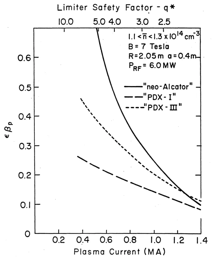
performance testing of components for these next devices. Furthermore, these parameters together give values of e0 >, 0.5, which put Alcator
DCT in the "finite-beta" regime of plasma equilibrium.
1.3. Programmatic Role
1.3.1. Role within the Toroidal Confinement Program Plan
The Toroidal Program Planning Office has prepared a plan which out-lines a program leading to the realization of an economically attractive
magnetic fusion reactor. It reflects the views of the toroidal confine-ment community and provides a framework within which to evaluate the role
of Alcator DCT.
According to the Draft Plan, the major program issues can be outlined
as follows:
A. Reactor Feasibility Issues
1. Demonstration of high power multiplication in moderate reactor
size.
1.1 Sufficiently high nTe-values for ignition. 1.2 Sufficiently low recirculating power.
2. Demonstration of high fusion power density with practical magnet systems.
2.1 Sufficiently high plasma beta value.
2.2 Sufficiently high ratio of field strength at the plasma to field strength at the magnet coils.
B. Reactor Development Issues
1. Demonstration of optimal plasma heating methods.
2. Control of plasma impurities and removal of fusion ash (helium).
3. Extension of pulse length to quasi-steady-state or even steady
state operation.
4. Control of gross plasma transients. C. Issues of Supporting Technology
1. Development of large superconducting-coil systems for operating
tokamak devices.
2. Development of long-lived first-wall materials and components for operating tokamak devices.
3. Development of cost-effective sources for RF and beam heating. 4. Development of the nuclear-engineering aspects of fusion power.
D. Issues of Reactor Design Optimization
1. Mechanical-components cost, lifetime and maintainability. 2. Auxiliary-systems cost and complexity.
As should be clear from the material presented in this chapter, the
primary purpose of Alcator DCT is to address the Reactor Development Issues of Plasma Heating, Impurity Control, Pulse Length Extension and Transient Control. This point is further underscored in Figure 1.3-1
which identifies the devices in which the Class A and B issues will be addressed, and which depicts Alcator DCT as the primary vehicle for
I-w I 0 C a N 0 L&J z 2 uJ 0 -w - C. 0~ 9= - .a. '-C * ~ U - ~ 0 (n ~ U o ---U, 0,
I-c
0
CL 0 0 0 In C, 0 a, In 0 0 0 77 C, 0, C 10 in Lu U, U,I
I-U a I Ii. 4 a a , C a 0,0-m7mmmo
I-IL I-. C 0 !6 7; a-. 3 --0. =2
ci I-4 Liu U C- I-z a I'. CI 'C U, 6-4 0, mm .2 to LuJ 0-4 0 C. U a E S-C4p
c 0 E 0, E U S c*-...!
on
c
C cp -0, 0 0 '" AWM* - -1-11
- I I.NO
E
An additional important role of Alcator DCT is to address the Class
C issues of supporting technology, especially issues C-1 and C-2.
With regard first to issue C-1, we note that plans for tokamak steps
beyond TFTR generally include superconducting windings either for both the TF and PF or for the PF alone. We argue that it will be excessively
risky to take that step without the benefit of an intermediate scale superconducting tokamak.
The benefit of intermediate steps has been recognized in the European fusion program, where Tore Supra will provide a superconducting technology background to be combined with JET to go forward into NET. The Soviet program through T-7 and T-15 is clearly pursuing a step-by-step build-up of superconducting background. Discussions are currently being held in Japan toward commissioning a superconducting up-grade version of JFT-2M
to provide this intermediate scale experience. Alcator DCT could provide an excellent intermediate scale superconducting tokamak background for the US program.
The mirror program has recognized the value of a step-by-step
intro-duction of superconductor technology. The recently successful MFTF Yin-Yang coil represented the third in a series of superconducting baseball coils built over a ten year period at Lawrence Livermore National
Lab-oratory. The tokamak environment will be more difficult than the steady-state nature of the mirror, placing an even greater premium on pre-steps.
The U.S. fusion program has invested heavily in the "Large Coil
Project" to gain intermediate scale experience in toroidal field magnets.
accommo-dating multiple approaches and encouraging testing beyond nominal
specifi-cations. It unfortunately has limitations in not adequately simulating a
true tokamak environment and in not forcing solution of a host of
integra-tion problems.
There are also limitations in some of the coil solutions chosen in
LCP. For example, because the coil specifications were very relaxed with
regard to disruption simulation, many of the conductors are not
suffi-ciently subdivided to guarantee stability under realistic disruption conditions. Peak fields in LCP are also limited to 8 Tesla. The one LCP
conductor which is considered sufficiently stable and extendable to higher field is the Westinghouse/Airco Nb3Sn conductor, which is the conductor we
have chosen for Alcator DCT.
Superconducting poloidal field coil development is far behind toroid-al coil development largely because nearly toroid-all available development re-sources have been devoted to TF development. Poloidal field conductors
differ from toroidal field conductors principally in their need to be sufficiently finely divided to limit pulse field losses and to remain
superconducting during PF field changes. The requirements for subdivision are in conflict with mechanical requirements in many of the proposed poloidal field conductors. A PF coil development program will clearly be
required before such conductors could be reliably used in next step ma-chines; Alcator DCT can provide an essential part of that necessary
devel-opment program.
An additional opportunity for technology contributions is the C-2 issue of first-wall materials and components. For example, there is
heat removal, although the high heat flux program will clearly pursue this
goal in a generic way. If the high-heat flux program were to take as one
of its goals the production of a steady-state rated generic tile, typically
5 x 5 cm, then Alcator DCT would be able to adopt them directly for use.
Similar interfaces could obviously be developed in the area of CW RF components and magnetics.
Alcator DCT could also provide an extended opportunity for inter-national cooperation in technology development. For example, there is a clear indication of interest in both Japan and Europe in expanding poloidal coil development and both see Alcator DCT as a near term driver for that development. The Japanese and European programs both see advantages to supplying portions of the Alcator DCT PF system, and in participating in
machine operations. Discussions have also been held on the possibility
of supplying some of the toroidal field coils from overseas programs.
1.3.2. Relationship to TFCD
Alcator DCT shares many probable features of TFCD and therefore pro-vides a suitable testbed. First wall high heat flux components and CW RF launchers are clear areas in which the TFCD requirements overlap with those of Alcator DCT. In the magnetics area, possible TFCD options vary
from all superconducting, to mixed copper and superconducting TF hybrid magnets, to copper TF magnets with superconducting PF magnets. Itis of
particular note that the central core PF coil in all the TFCD options is
quite comparable to the Alcator DCT transformer. This is largely because
the aspect ratio of 5 in Alcator DCT permits a large transformer space. Development of components for Alcator DCT transformer therefore provides
a direct development for TFCD. By the same token, any early development
activities for TFCD can provide upgrades for Alcator DCT which can, in
turn, serve as a long-pulse qualification test bed.
The toroidal coils in Alcator DCT will utilize high current conduc-tors which are directly extrapolable to TFCD should a superconducting TF coil option be chosen. The Alcator DCT Nb3Sn TF conductor will also be suitable for use in a TFCD PF central core transformer should it be nec-essary to choose a higher field for the TFCD core, or to provide
addition-al stability margin to meet the TFCD requirements.
The availability of a small machine like Alcator DCT to serve as a
test bed and as an early confirmation of concepts can easily pay for
itself many times over in a project of the scale of TFCD. The schedule relation of the two projects is shown in Figure 1.3-2, as well as the interrelation which would be possible in an area such as PF development. The development shows a parallel path in which: 1) early developments
would be utilized in Alcator DCT and qualified for use as detailed design
concepts for TFCD, and 2) subsequent, more optimized developments could be fed back into Alcator DCT upgrades and become TFCD component
qualif-ication tests. A similar parallel path strategy can be evolved for first wall components and CW RF systems.
1.3.3. Relationship to other Experiments
1.3.3.1. Existing Copper Devices and their Upgrades
All existing tokamak devices in the U.S. (see Figure 1.3-1) have
pulse lengths of about 1 s, which is clearly too short to address the
long-z
0 .3 w 2 Ch L~iz 0 0 IL 0.Uw
w
00 U)z
-JL&J0 000a:11
loa
i
N3bWdO3A3(1
r~)
c~J
0)
0D
OD
OD
I,-O
ODvo
OD,LL
-U C4 10 cnpulse issues within the context of the existing program will require, at
a minimum, substantial extension of the capabilities of these facilities.
In general, the areas in which long-pulse upgrades would have to occur are: duration of the auxiliary heating pulse; capacity of the cooling systems; protection of the first-wall; and increase of the
trans-former volt-seconds available for current flat-top. The minimal cost of such enhancements to any existing tokamak within the U.S. program, in order to achieve pulse lengths on the order of TS, is equal to or somewhat
greater than the cost of the proposed Alcator DCT.
In addition, choosing the path of enhancing the performance of an
existing copper device(s) for the purpose of pulse length extension has a
number of significant disadvantages relative to proceeding with Alcator
DCT:
* At best, the pulse length would be equal to one skin time, and this is achievable only with sub-optimal plasma parameters. Hence, time scales in excess of the skin time which might allow stable routes of access to optimized high performance regimes
(for example, through profile control) would be prohibited.
Degradation in parameters derives from the fact that the TF and possibly the PF magnet systems must be derated for long pulses, since they were originally designed for short-pulse, low
* Development and demonstration of quasi-steady and true
steady-state modes of operation by lower hybrid current drive at reactor-relevant parameters would be prohibited, owing to the low toroidal field.
* Inadequate impurity control methods, especially the lack of an appropriate divertor, may limit the pulse length and result in
unoptimized regimes.
* No TFCD/ETR-relevant technology contributions nor integration
experience would be gained in the superconducting magnetics area. Except for the lack of adequate impurity control methods, the foregoing
disadvantages also apply to a comparison of Alcator DCT with ASDEX-UPGRADE, to be built at Garching, FRG. It is concluded, then, that
although pulse length extension in existing copper devices may be feas-ible, the cost to the OFE program will be at a minimum equal to that of
Alcator DCT. Such extended performance devices can, at best, address
only a small subset of the important issues which would be addressed by Alcator DCT.
1.3.3.2. Comparison to Tore-Supra
Finally, it is appropriate to comment on the relationship of Alcator DCT to Tore-Supra, which is the only other funded tokamak with long-pulse objectives outside of the Soviet Union. A U.S.-France workshop was
held in Cadarache, France in June 1983, to examine the capability of Tore-Supra in addressing long-pulse issues and to compare the Tore-Supra
by attending members of the Alcator DCT team is on file in OFE
Headquar-ters, as is a report prepared jointly by OFE and non-M.I.T. personnel. In the remainder of this section, a synopsis of the comparison prepared by the M.I.T. team is presented.
A comparison of the physical characteristics of Tore Supra and Alcator DCT is provided in Table 1.3-1.
TABLE 1.3-1
Physical Characteristics of Tore-Supra and Alcator DCT
Tore-Supra
Plasma major radius, RO Plasma minor radius Vacuum vessel bore
Toroidal magnetic field (R = RO) Maximum field in conductor
Toroidal field coil mean diameter TF conductor
Weight of superconductor
Total magnet weight
Total magnetic energy Plasma current (q - 3) Maximum discharge duration Poloidal field conductor Total flux swing (R = RO)
Flux available for current plateau Weight of induction coil
2.25 m 0.70 m 1.8 m 4.5 T 9.0 T 2.6 m NbTi 45 t 160 t 600 MJ 1.7 MA 30 s Cu 21 Wb 8 Wb 56 t Alcator DCT 2.0 m 0.40 x 0.56 m 1.1 x 1.56 m 7.0 T 10.0 T 1.5 x 2.0 m Nb3Sn 66 t 180 t 580 MJ 1.0 MA NbTi 35 Wb 25 Wb 30 t
The toroidal field magnets for both machines are superconducting: NbTi
in Tore-Supra and Nb3Sn in Alcator DCT. Tore-Supra is larger, having 20%
greater major radius, and has slightly more than twice-the cross-sectional area. Alcator DCT has a higher toroidal' field (7 T vs. 4.5 T) and the stored energies in the toroidal magnets are nearly the same. The poloidal
field system in Tore Supra is fabricated from water-cooled copper coils and this limits the maximum pulse length to 30 s at full current, which is 1.7 MA at q - 3. The poloidal field system in Alcator DCT is
fabri-cated from NbTi superconducting coils and there is no limit on pulse length. The q = 3 current is 1 MA for circular plasmas and the poloidal system is capable of 1.5 MA plasma current at lower q or with elongation. The transformer flux swing in Tore-Supra is 21 Wb with 8 Wb available for
current flat-top and this compares with 35 Wb and 25 Wb respectively in
Alcator DCT. At the same central temperature and Zeff, Alcator DCT would be capable of about twice the pulse length.
Special capabilities of Tore-Supra and Alcator DCT are compared in