BioJADE: A Design and Simulation Tool for
Synthetic Biological Systems
by
Jonathan Ari Goler
Submitted to the Department of Electrical Engineering and
Computer Science
in partial fulfillment of the requirements for the degrees of
Master of Engineering
and
Bachelor of Science in Electrical Engineering and Computer Science
at the
MASSACHUSETTS INST1Jrf
MASSACHUSETTS INSTITUTE OF TECHNOLOGY
OFTECHNOLOGYMay 2004
JUL 2 0 2004
@
Jonathan Ari Goler, MMIV. All rights reserved.
LIBRARIES
The author hereby grants to MIT permission to reproduce and
distribute publicly paper and electronic copies of this thesis
document in whole or in part.
A uthor...
Depa ment of Electrical Engipieering and Computer Science
4 /
r
/
i/
May 18, 2004
Certified y... ... ...
...T omas F. Knight Jr
Senior Research Scientist
EThsisjupervisor
Accepted by...
Arthiur C. Smith
Chairman, Department Committee on Graduate Students
BioJADE: A Design and Simulation Tool for Synthetic
Biological Systems
by
Jonathan Ari Goler
Submitted to the Department of Electrical Engineering and Computer Science on May 18, 2004, in partial fulfillment of the
requirements for the degrees of Master of Engineering
and
Bachelor of Science in Electrical Engineering and Computer Science
Abstract
The next generations of both biological engineering and computer engineering de-mand that control be exerted at the molecular level. Creating, characterizing and controlling synthetic biological systems may provide us with the ability to build cells that are capable of a plethora of activities, from computation to synthesizing nanostructures. To develop these systems, we must have a set of tools not only for synthesizing systems, but also designing and simulating them. The BioJADE project provides a comprehensive, extensible design and simulation platform for synthetic bi-ology. BioJADE is a graphical design tool built in Java, utilizing a database back end, and supports a range of simulations using an XML communication protocol. BioJADE currently supports a library of over 100 parts with which it can com-pile designs into actual DNA, and then generate synthesis instructions to build the physical parts. The BioJADE project contributes several tools to Synthetic Biology. BioJADE in itself is a powerful tool for synthetic biology designers. Additionally, we developed and now make use of a centralized BioBricks repository, which enables the sharing of BioBrick components between researchers, and vastly reduces the barriers to entry for aspiring Synthetic Biologists.
Thesis Supervisor: Thomas F. Knight Jr Title: Senior Research Scientist
Acknowledgments
I would first like to thank my thesis advisor, Professor Thomas F. Knight Jr. for
getting me into Synthetic Biology, and showing me the ropes, and supporting my various endeavors in the year and a half that I have worked in his lab.
Randy Rettberg helped me tremendously with learning BioBrick design, and with the development of the BioBricks Registry. Austin Che assisted me in bootstrapping the registry and for writing the code that the basic registry was based on. Reshma
Shetty and Drew Endy provided a great deal of insight and help debugging and enhancing the repository. Felice Frankel helped with the design and user interface elements of BioJADE and helped me make it into an elegant and usable tool. Ad-ditionally, I thank Gerald Sussman for 6.978 where I first met TK, and worked out some preliminary interesting applications of SynthBio. In addition, I thank Professor Patrick H. Winston for his insights on writing and communicating effectively. His teaching is perhaps the most effective and compelling at MIT.
Naturally, many thanks go out to my parents, and grandparents for their support for my work here. My friends Dana Spiegel, Jose Gonzalez, Ariela Ressler, Stefan Be-wley, Tomer Posner and Zofia Gajdos for always being there. MaryEllen McLaughlin for believing in me to give me a chance, and molding me into something a little less flimsy than when she began, and Professor Josef Kurtz for always challenging me to do more and better. And of course, the whole MIT Swimming and Diving team for all of your support through the last five years.
Contents
1 Introduction 15
1.1 Differences in Biology and Silicon . . . . 15
1.2 System Overview . . . . 17
1.2.1 Parts Repository . . . . 17
1.2.2 BioJADE . . . . 17
2 Background 19 2.1 Basic DNA Functionality . . . . 19
2.2 Initial System Inspiration . . . . 21
2.3 The BioBricks Standard . . . . 21
2.3.1 BioBrick Definition . . . . 22 2.3.2 Assembly . . . . 23 2.3.3 Assembly++ . . . . 25 2.3.4 Characterizing Parts . . . . 26 2.4 Biological Limitations . . . . 27 2.5 Potential Applications . . . . 27 3 System Design 29 3.1 Basic Architecture . . . . 29
3.2 Aspects . . . . 30 3.3 Part Repositories . . . . 30 3.4 The Database . . . . 31 3.4.1 Implementation . . . . 31 3.4.2 Access Methods. . . . . 31 4 Aspects 35 4.1 The Aspects . . . . 35
4.2 The Aspects in the Basic BioJADE package . . . . 36
4.3 Schematic . . . . 37
4.4 Functional Network Aspect . . . . 41
4.4.1 Adding Species and Reactions . . . . 43
4.4.2 Refining Auto Part Selections . . . . 43
4.5 Simulation Aspect . . . . 45 4.6 Icon Aspect . . . . 47 4.6.1 Dynamic Terminals . . . . 48 4.7 DNA Aspect . . . . 48 5 Simulations 51 5.1 D-FLUX . . . . 51 5.1.1 The Architecture . . . . 52 5.2 Standard Simulators . . . . 54 5.2.1 Stochastirator . . . . 54 5.2.2 Tabasco . . . . 55 5.2.3 Electrical Models . . . . 56
6 Modeling Biology and Devices 59
6.1 Basic M odels . . . . 59
6.1.1 General Treatment of Cellular Species . . . . 59
6.1.2 Ribosome Binding Sites . . . . 60
6.1.3 Coding Regions . . . . 61
6.1.4 Term ination . . . . 61
6.1.5 Promoter Binding and Repression/Expression Control . . . . . 61
6.2 D evice M odels . . . . 62
6.2.1 Quad Part Inverters . . . . 63
7 Compiler Issues and Optimizations 65 7.1 Logic Reduction . . . . 65
7.2 Managing Biological Uncertainty . . . . 66
7.3 Possible Optimizations . . . . 67
8 Future Work 69 8.1 Potential Dangers . . . . 70
8.1.1 Friendly Warnings Help Avoid Accidents . . . . 70
8.1.2 Open and Secret . . . . 70
8.1.3 Education . . . . 71
8.1.4 M onitoring . . . . 71
9 BioJADE's Contributions 73
List of Figures
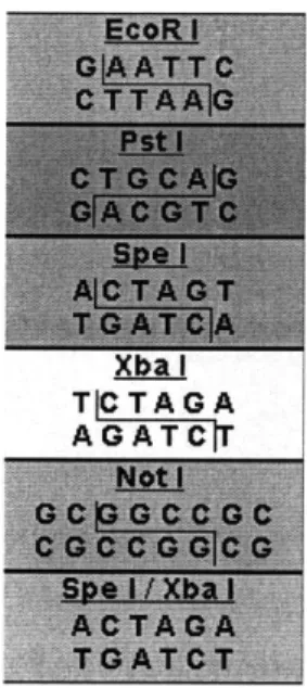
2-1 RNA Polymerases arrive and produce the mRNA (messenger RNA) transcript in the 5'-3' direction along the template DNA. . . . . 20 2-2 Standard BioBrick Restriction Sites. These sites must not be included
in any part, otherwise the assembly protocol will fail. . . . . 22
2-3 A base part with the BioBrick prefix and suffix. The XbaI and PstI
sites are used to cut the part when it is used in an assembly. There are a few extra bases inserted to separate the cut sites. [26] . . . . 23
2-4 The base plasmid provides matching XbaI and SpeI sites for inserting the part into the plasmid. . . . . 23 2-5 The XbaI and PstI sites on the insert and plasmid are both cut, and
the overlapping ends are ligated, producing the part within the vector. 23
2-6 An overview of the Standard Assembly Process [14, 26]. This diagram
shows the idempotent assembly procedure where the output from one cycle is an input into the next. . . . . 24
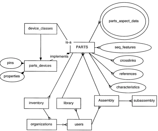
3-1 The Parts Database is a star-type schema for part data. In addition,
support for users, organizations, part assembly and inventory man-agem ent is provided. . . . . 33
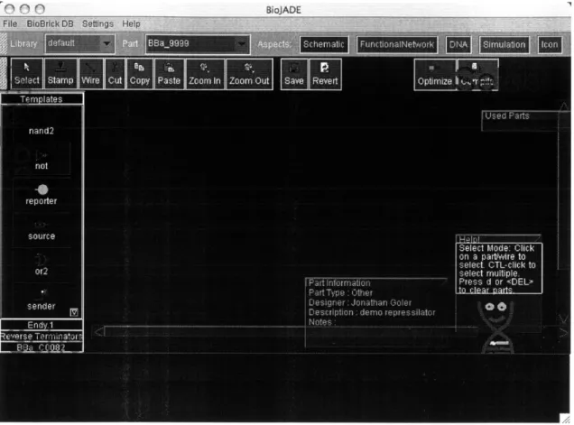
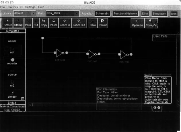
4-1 Schematic Design Mode. This figure shows the initial state of the schematic aspect. We have selected the not part prototype from the palette on the left. . . . . 38
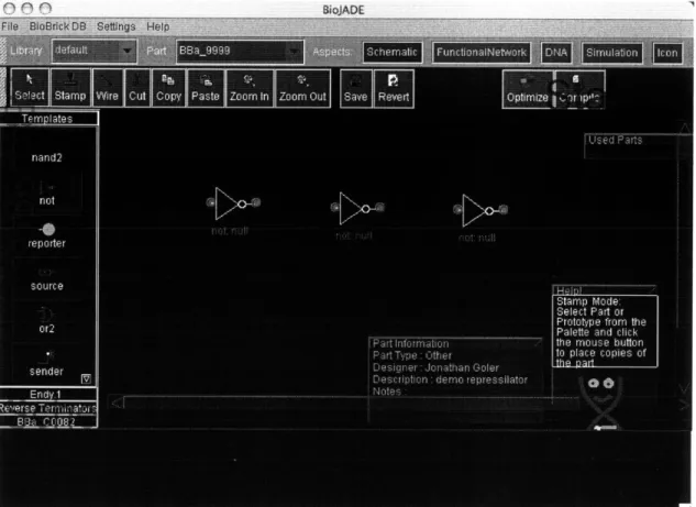
4-2 Schematic Design Mode. This figure shows three blank not gates being stamped out on the design. Note the context-sensitive help in the lower right corner. . . . . 39
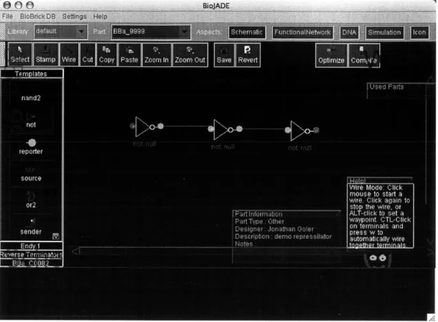
4-3 Schematic Design Mode. This figure shows the three gates being wired together. The terminals change color from red to green when they are connected to other components. . . . . 40 4-4 Schematic Design Mode. This figure shows the completed schematic
of a repressilator. . . . . 41
4-5 The Functional Network Representation shows the same repressilator, but in the form of stretches of DNA. System features such as ribosome
binding sites can be selected from the functional network aspect. . . . 42
4-6 The Functional Network mode also enables the designer to specify other species and reactions that affect system performance. This figure shows a degradation reaction involving one of the signaling molecules. 44 4-7 Editing promoter details such as the cooperativity in the Functional
Network m ode. . . . . 45 4-8 The same repressilator simulated with Stochastirator. The figure
shows the oscillation of all three signaling molecules. . . . . 46
4-9 Drawing a dynamic terminal onto the icon representation for a wired-NOR gate. The red terminal is a normal terminal, and the green arc on the left is the dynamic terminal area. . . . . 47
4-10 Examining the repressilator in the DNA Aspect. The DNA Aspect dis-plays sequence data along with a graphical representation highlighting the annotation of the DNA. . . . . 49
5-1 DFLUX gives designers shared access to powerful computational
re-sources to execute simulations. . . . . 57 5-2 A Tabasco simulation visualization that shows(in quicktime format)
the generation of mRNAs and their associated proteins. The levels of each species is shown at the upper left corner. The DNA is shown as a line, with green blocks representing transcription starts, and yellow blocks representing termination. The blue or green ovals on top of the DNA are the polymerases, which move along the DNA. Finally, below the DNA are lines and a number representing mRNA transcripts produced by the DNA blocks above them. . . . . 58
Chapter 1
Introduction
The development of synthetic biological systems will be driven in large part by our ability to design and analyze complicated systems built out of many components. In the development of microprocessors, the introduction of VLSI design and simulation tools greatly improved the capabilities of chip designers. While synthetic biology is at the point where such tools would be highly beneficial, none have yet been developed. BioJADE is based on JADE (JAva Design Environment), which was written by
Chrisopher Terman, James Knight and Milan Minsky of MIT LCS [25]. BioJADE
differs from JADE in several respects, and incorporates a number of different data structures and data access methods that are necessary due to the use of biology rather than physical substrates.
1.1
Differences in Biology and Silicon
There are a variety of differences between Silicon and Biology that make existing representations of electric circuits insufficient for describing genetic networks or
cir-cuits. The most important of these differences is that the notion of a wire as a localized object in physical space is completely different in biology. The basic units of control, such as the components comprising inverters, are not necessarily in the same place. For example, a basic Lac inverter could be made, using input from an-other component to produce a protein that represses a promoter on anan-other part of the genome. The wires in our design are constraints that define what components must be in sequential order on the DNA. In addition, the RNA, proteins and small molecule signals constrain the choices of components because those species interact with each other as well as promoter regions of DNA. One significant problem with thinking about wires in this manner is that for components to be distinct, we need distinct proteins/RNAs. Without distinct molecules, our signals will be garbled.
The second primary difference is the speed of operation. Silicon allows us to perform complex computations very quickly due to the nature of electrical signals. Electrical signals propagate near the speed of light (and new photonic systems do operate at the speed of light). Biological signals, particularly prokaryotic ones are molecules, some small like sugars and some large such as proteins or DNA. Most of these signals propagate as they diffuse through the organism. In addition, by using transcriptional regulation to build logic functions, speed is limited by the speed of transcription and translation. For quicker functions, Muir [20] showed how to combine a split protein, which could be non-functional when apart, and functional when combined. The folding process is far faster than transcriptional regulation.
1.2
System Overview
1.2.1
Parts Repository
There are two primary components of the BioJADE system. The first component is the BioBricks repository system, the first instance of which is the MIT Registry for Standard Biological Parts. The repository system is a database driven website that contains all of the BioBricks that are currently either designed or available for use. The Repository contains not only the part definitions, including annotated sequence data, but also interfaces for editing and viewing auxiliary data. The database allows designers to edit and view associated papers, figures, and behavioral parameters.
The Repository system is implemented as a Data Model and Perl interface for the web access. Perl was chosen because of legacy applications, including a prototype Parts Repository written by Austin Che [2]. Che's prototype included the basic data, but was backed by flat files. The Repository system now uses a relational detabase
(RDBMS), in this case, Oracle 9i.
1.2.2
BioJADE
BioJADE is the design and simulation tool. With BioJADE, a user can connect to either a partial flat file parts repository in XML format, or a full RDBMS. The designer then has the ability to design new parts or analyze the behavior of parts in his repositories. In the design mode, the designer can build a system by stamping out parts(either prototypes or specific implementations), and connecting them using 'wires'. The designer then 'compiles' the design into more specified designs, such as
DNA or functional networks, that expose the underlying biology.
anno-tated DNA sequences in plasmid format from the design. Designers can arrange the parts along the plasmid, and modify their interactions. In addition, the designer can view and modify more complicated functional behavior of component interac-tions such as anti-sense reacinterac-tions, small molecule transduction and RNA/Protein
degredation.
Once a system is designed and its components are specified, the next step is to simulate their combined behavior. Just as in JADE or SPICE, there are a variety of simulations that can be used. These simulators range from a system level simulator that tests the logic without regard to time, to simulators that work down to the level of proteins binding and moving polymerases along the DNA. The simulation interface yields extreme compatibility and flexibility. The interface permits the use of tools written in different languages, on different platforms. The interface wraps existing tools and makes them available to BioJADE designers. In addition, the interface allows distributed simulation, so that designers can harness much more powerful computers to simulate their design.
Finally, the designer submits the design to a BioBricks parts repository for other users to use in their designs. Once on the site, the author executes an assembler and generate assembly instructions for building the parts, making use of the entire library of existing parts.
Chapter 2
Background
This section deals with the fundamentals of synthetic biology as it applies to the problem of building synthetic biological computational units. This section explains how and why synthetic biological systems work, as well as their benefits and lim-itations. Finally, this section explores a few examples of how synthetic biological systems might be harnessed to improve our lives.
2.1
Basic DNA Functionality
DNA is the basis of how our cells work, and how we develop as human beings. DNA, along with RNA, proteins and small molecules, is the basis for every living
thing, from a prion to a giant squid. The sequence of DNA, the A,T,C, and G's, can determine what proteins we produce, and whether or not they are produced correctly. The sequence itself does not entirely determine the resultant proteins due to alternate splicing and these sequences do not completely determine what happens to us, because DNA is only a part of a more complicated system.
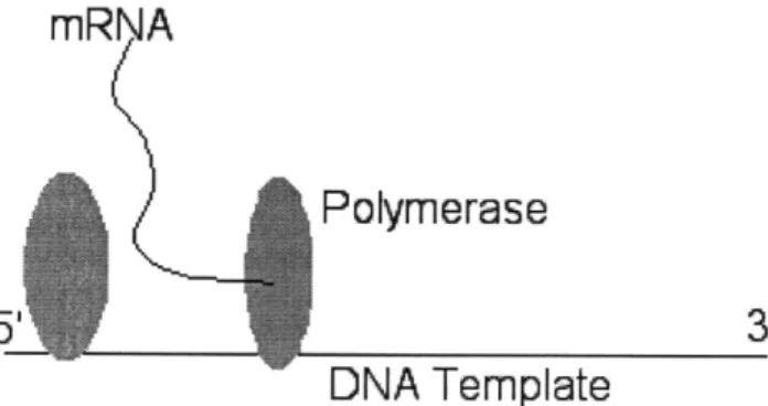
When a protein known as a DNA polymerase attaches itself to part of the DNA, it then moves along the DNA, building an RNA transcript. This process is called transcription. Different polymerases exist in different cells, and they each work with differing speeds and accuracies. Transcription is halted when a polymerase encounters a terminator. Terminators are usually stem loop secondary structures in the DNA that literally cause the polymerase to fall off the DNA. Terminators are not perfect, and some BioBrick terminators are actually two in series, so that if one fails, the other is likely to succeed.
mRNA
Polymerase
5'
3'
DNA Template
Fig. 2-1: RNA Polymerases arrive and produce the mRNA (messenger RNA) tran-script in the 5'-3' direction along the template DNA.
The resulting mRNA, which then is free to interact with ribosomes, might then be bound by a ribosome. The part of the mRNA to which a ribosome binds to is known as the ribosome Binding Site (RBS). There are a variety of RBSes, and they have differing binding affinities. Thus, we can control the activity of the ribosome binding through selection of the RBS. Once attached, the ribosome builds a protein one amino acid at a time by matching tRNAs to each codon (3 base sequence), until it reaches a stop codon. Proteins then fold and perform their function, which includes binding to regulatory regions of other DNA parts, or florescing, etc. Proteins are
degraded regularly by proteases, and this degredation can be quickened by adding
LVA/LAA tails to the proteins that help mark them for 'garbage collection'.
2.2
Initial System Inspiration
A few sample systems have been instrumental in our understanding of gene
regu-lation and cell-cell signaling. One such system, the Lux system, has been studied extensively by Greenberg et al. [6, 7, 10, 15, 3]. These systems were then used by Knight and Weiss to implement communication and logic gates [29, 5].
Other systems, such as the periplasmic binding proteins investigated and ex-ploited by Hellinga, can be modified computationally to respond to non-native lig-ands [17, 30] , giving us a greater variety of inputs for synthetic systems.
By integrating existing systems with new parts, we can expand our ability to build
interesting biological systems. The existing templates we have of control systems in nature give us hints on what is possible, and by altering the existing systems, we learn how to break them. Vilar and Leibler [11, 27, 28] have used synthetic biological systems to study noise resistance in oscillatory networks, and incorporate more robust measurements into models. These synthetic systems are not only useful for engineering systems, but also understanding the mechanisms for natural system performance.
2.3
The BioBricks Standard
The BioBricks Standard, developed by Thomas F. Knight Jr. [14], provides a
mod-ular way of builiding and composing parts made out of DNA. The Standard consists of specific prefixes and suffixes that enable the composition of parts in a standard
way. There are currently a few ways of composing parts, the Idempotent Standard Assembly method and the Triple Antibiotic Assembly [23] known as the 3A method.
2.3.1
BioBrick Definition
The BioBricks parts are comprised of their contents, and standard biobricks ends. The contents are arbitrary, with the caveat that they may not contain any of the BioBricks restriction sites (EcoRI XbaI, Spel, NotI and PstI). These sites can be mutated out through manual edits of the sequence. In most cases, changes can be made that do not affect the system due to the redundancy in the codon specificity.
The prefix for a part is a cett +XbaI + g site, and the suffix is a t
+
Spel + a + NotI + PstI + cctt. The restriction sites enable the idempotent construction, while the extra bases help to separate restriction sites and allow the enzymes some overhang at the ends.AD& I
T[C TAG A AG AT C
Fig. 2-2: Standard BioBrick Restriction Sites. These sites must not be included in any part, otherwise the assembly protocol will fail.
Parts are grown and stored in plasmid vectors. These vectors are circular pieces of DNA that bacteria exchange with each other. There is a set of standard BioBrick plasmids that are used to build and grow parts. They contain sites that enable the introduction of the BioBrick parts.
cctt Xba CONTENTS t Ispel Ia m- NoIlPstj cctt7
Fig. 2-3: A base part with the BioBrick prefix and suffix. The XbaI and PstI sites are used to cut the part when it is used in an assembly. There are a few extra bases inserted to separate the cut sites. [26]
t gt a
Fig. 2-4: The base plasmid provides matching XbaI and Spel part into the plasmid.
t Xbal CONTENTS
t
sites for inserting the
a
Fig. 2-5: The XbaI and PstI sites on the insert and plasmid are both cut, and the overlapping ends are ligated, producing the part within the vector.
2.3.2
Assembly
To put parts together, we cut the parts with the appropriate restriction enzymes and then ligate the cut products together. In this example, we place one part on the beginning of another part.
BBa Parts
Fig. 2-6: An overview of the Standard Assembly Process [14, 26]. This diagram shows the idempotent assembly procedure where the output from one cycle is an input into the next.
!
BBa_BO001 Or 2Base Vector BBa_90003Competent Cells
13B Part Inserted Into Vector
I
I
I
The key to the idempotent assembly process is the convenient nature of the XbaI and Spel sites. The overhang is identical, but the ends of each cut site are different, so the combined site can be ligated, but not cut. Yet, the ends remain the same, and thus, we can compose parts again and again.
For the component that we are prepending, we take the DNA and cut it with EcoRI, and XbaI. The component we are inserting is cut with EcoRI and Spel. These components are then ligated together and the result is the combined part, with the same ends, but with an uncuttable mixed SpeI/XbaI site where they were ligated.
The Triple Antibiotic (3A) assembly technique is an extremely useful way to put parts together. We utilize biology's selection mechanisms to do the hard work of ensuring that the resulting part is correct.
The procecure is not discussed here, but see the reference on 3A [23] in the bibiography for more detailed information about the 3A assembly process.
2.3.3
Assembly++
The BioBricks Alpha Specification[16], is one of many possible assembly techniques. There are a variety of possible assembly techniques that would require modifying the ends of the parts, but the basic essence of the parts should remain the same. In addition, improved assembly techniques, such as Austin Che's BioBricks++ [1],
offer other assembly options.
Even as new assembly techniques and part ends are developed, the notion of modularity and its advantages continue to apply to the development of systems. Therefore, BioJADE is not vitally concerned with assembly technique until the actual design is compiled into the assembly instructions for a particular assembly process.
2.3.4
Characterizing Parts
Part of having a standard includes having a way of measuring system behavior in a repeatable, and standard way. We want to know several parameters, such as minimum and maximum signal levels, transfer functions, transcription load on the organism, crosstalk and other incompatibilities. With a simple example, like an inverter, which is composed of a coding region, the associated mRNA and proteins, and the regulatory region it binds to already provide a complicated system.
Must we know how fast each of these components is produced, degraded or dif-fused? Or would it suffice to know how fast and how well an input signal gets mapped to the output signal? The "signal in, signal out" form would be desirable. We have defined two terms: TIPS: transcription initiations per second, and PAR: polymerase arrival rate, to indicate signal level on both input and output. We can measure this characteristic directly using the PARMASAN method of Austin Che[2l. This
method allows us to directly observe the polymerase arrival rate on parts.
Nevertheless, the diffusion and degradation properties of these signals are impor-tant in determining timing characteristics of the system, including the rise time, fall time, and propagation delays that are vital in system design. Thus, we must measure all of these values.
Finally, these values are not constant across conditions and organisms. Thus, we will have to develop tables of values for the parts, including the organism used and the conditions in which the measurements are conducted. Once a significant number of these values have been determined, more generalized behavior can be better estimated.
2.4
Biological Limitations
Biology, as useful as it is, has significant limitations. For one thing, organisms die, for myriad reasons. In addition, we are hampered by the inherently slow and sometimes very noisy processes of diffusion and transcription/translation. As a result, logic functions(such as super fast arithmetic) might not be ideal applications for compu-tation using synthetic biology, except in cases where massive parallelism is usable, because it is very easy to grow a big vat of biological processors.
Biology also offers us the benefits and curses of evolution. We might have a part that we can use mutation to improve, or we might have a part whose behavior is undesirably modified or removed. In several instances of part synthesis of some of the first biological blinker systems 1, there are systems that are detrimental to the host in their intermediate form, causing too much load on the chassis, and are removed or modified by evolution.
So we must find a way to understand how our parts interact with the existing biology of the cells. The efforts of Knight et al, to create a minimal Mesoplasma
florum
will be useful in removing many interactions and load from the cell. A simple cell, such as the minimal Me florum, gives synthetic biologists more freedom in their designs.2.5
Potential Applications
Synthetic biology has the potential to greatly affect our ability to control and sense the world around us. There are a variety of applications of synthetic biology that
'In January 2003, a group of MIT students learned the basics of synthetic biology, and designed
'blinkers' that oscillated emitting light. The systems were still being synthesized as of Fall 2003 due to difficulties encountered during synthesis
have the potential for great benefit, but also for great peril.
At this point, the organisms we create are so weak and stressed that breathing on them the wrong way kills them. However, this feature is partially by design. Nothing we create has much potential to cause problems in the greater world.
However, in the near future, we expect to be able to develop systems that are capable of detecting minute quantities of chemical and biological signals, such as anthrax, poison gas, etc. These sensors would have to be able to react and survive in the external environment, at least for a limited amount of time.
There are numerous applications, the general groups of which are listed below.
" Energy Production and Storage
" New Devices and Assembly (at the nanoscale)
* Molecular Medical Devices * Bioreactors
* Programmable Devices and Control Logic
" Smart Materials " Sensors
* Complex Assembly (large functional organisms like self-assembling bio-houses)
" Terraforming
In most cases, these applications require control logic within the cells, and our standard parts give us a modular, and standard way way to achieve this control logic. In addition, components such as sensing proteins are also useful and introduced through synthetic biology.
Chapter 3
System Design
This chapter provides a detailed description of the BioJADE system architecture, and discusses the design choices and considerations in building the system. For a user who is merely looking to use the system, this chapter will not be central. However, this chapter should provide some insights into designing a complicated system with the need to merge conventions between Computer Science, Electrical Engineering, and Biology.
3.1
Basic Architecture
BioJADE is built on top of the BioBricks part representation model. This model includes the design and specification of part features, behaviors and graphical repre-sentations. The system requires one or more repositories for storage and publication of part data.
The system keeps a cache of parts from the data stores and caches changes until they are committed to the database itself. This cache enables fast response time for
the user interface. The basic architecture is derived from Jade[25]. However, we use significantly different data structures to handle the differences between silicon and biological substrates.
3.2
Aspects
Each part has several Aspects, which encapsulate a way of viewing and interacting with a part. Our model of Aspects was derived from Chris Terman's in Jade. When BioJADE is started, it reads a list of available aspects from the configuration file. These Aspects are displayed for the user, and while a part is selected, a user may switch between aspects. To facilitate easy navigation, the Aspect abstract class supports saving data in memory for each part so that changes can impact the current workspace without being committed to the data store.
3.3
Part Repositories
I built in two types of storage options for BioJADE: JDBC/Oracle and XML. To
accommodate the two different types of access, I built the interface "BBDataStore" which both BioBricksDatabaseClient(BBDBC) and BioBrickXMLClient(BBXML) implement. BBDBC supports connections to an Oracle or MySQL database that con-tains the BioBrick Data Model. BBXML supports connections to an XML Database on a file system or across HTTP. Since primary development of the system relied on the concurrent development of the MIT Registry of Standard Biological Parts, the vast majority of testing was done on BBDBC.
Should new forms of storage become necessary, a user might simply create a new implementation of BBDataStore and install it into the BioJADE packages.
3.4
The Database
3.4.1
Implementation
We implemented the Parts Database on an Oracle 9 RDBMS. The database supports not only the full description of parts, but also tracks stocks of parts that are held at various labs, and associated files such as papers, data charts, or diagrams. The main details for the parts are held in the parts table, while ancillary information and information that would be represented as an array or vector is held in a variety of auxiliary tables. Figure 3-1 describes the organization of the Parts Schema. A complete listing of the table definitions is provided as Appendix A. In addition, the data model has been ported to MySQL for those organizations that do not have a license for Oracle.
This star-type schema permits the simple addition of additional fields should they be necessary. Oracle was chosen as the database for several reasons, including its robustness, powerful Large Object (LOB) support, and the author's familiarity with its operation. It has not escaped our notice that Oracle is both extremely expensive and unwieldy to install for many users. MySQL is a free, viable option for an alternative for the database back-end. We have provided a version of the BioBricks schema that works with MySQL.
3.4.2
Access Methods
JDBCA JDBC client can access the Parts database remotely over the network. To
con-nect, the client needs the Oracle JDBC driver (provided with the source/binary distributions), along with the host name, database instance name, and
authentica-tion informaauthentica-tion. This data is also included with the distribuauthentica-tion. The client relies on the thin implementation of Oracle JDBC, and thus does not require the installation of the Oracle Client Interface(OCI).
The MySQL client requires the MySQL JDBC connection classes, which is freely available from the MySQL website.
Perl/DBI
We use Perl DBI to access the database for the purpose of implementing the web interface to the Parts Database. This method requires installing Perl, DBI and DBM::Oracle modules, as well as the Oracle Client. In the interest of conserving database resources, all web interfaces should utilize cached connection(DB Handles) and Prepared Statements. In addition, prepared statements not only improve per-formance, but they enhance security through parameter binding, so that there is no chance of introducing hostile code into executed SQL.
parts-aspect-data deviceclasses is-a PAT aj parts_ evicesipeet propetiesreferences characteristics
inventory library Assembly subassembly
organizations users
Fig. 3-1: The Parts Database is a star-type schema for part data. In addition, support for users, organizations, part assembly and inventory management is provided.
Chapter 4
Aspects
The Aspects define several different ways of viewing and editing parts. They cover the gamut of specifiying and twiddling individual base pairs of DNA, to importing a pretty picture to represent the parts as they get incorporated into new and larger parts. It is useful to go through the list of aspects as one would go about designing parts. Therefore, the majority of the discussion focuses on the design stages of a part, as a user might go through them.
4.1
The Aspects
Each part has several Aspects, which encapsulate a way of viewing and interacting with a part. Our model of Aspects was derived from Chris Terman's model in JADE. When BioJADE is started, it reads a list of available aspects from the configuration file. The list of available aspects is displayed in the toolbar, so that a designer may switch between them at any time.
data to its data store. Because each aspect has its data represented differently, the individual editors handle actually storing the state to the aspect, which in turn renders it into the data store's XML format.
In addition, the Aspects keep track of the current state of all opened BioBricks, so that if you make a change in one part, and then switch to another part, the changes are not lost. This temporary storage is merely a hash table keyed on the BioBrick. This representation is very useful for making changes to parts while not committing them to the database.
4.2
The Aspects in the Basic BioJADE package
Schematic Supports drag and drop circuit design of more complicated BioBricks. The Schematic Aspect permits the user to lay out generic devices and then,
with a mouse click, 'compile' the design into its actual component parts, along with the associated assembly instructions.
Icon Permits the user to upload a PNG/GIF/JPEG file to display for the part,
and provides a tool for marking the terminals of the device so that it can be connected to others in the Schematic Mode.
DNA Displays the annotated DNA Sequence.
Functional Network Shows a more detailed Biological-Type view of the system,
which permits the user to see more rate constants and tune the design.
Simulation Interfaces to all of the available simulation tools, as well as the status
4.3
Schematic
The Schematic Design mode enables users to lay out circuits made out of genetic components just as they would a circuit made of silicon. The Design mode present a toolbar that contains available libraries of parts to stamp on the design. In addition, a toolbar containing basic functionality such as cut, copy, paste and buttons for drawing wires and stamping parts is docked to the top of the workspace. The rest of the workspace is dedicated to the design itself. Users can scroll and zoom the workspace to focus on different aspects of the design.
Designers build circuits by selecting a part or prototype from the part palette on the left, and selecting the stamp button on the toolbar. The designer then stamps down the part onto the design. The user can then click on the Select button to revert to being able to merely select objects already on the design and move them around to wherever they wish.
The designer then selects the Wire tool and draws wires between the components. The first method for drawing wires is to select the starting terminal and dragging the wire to the ending terminal. The wires conveniently snap to the terminals of devices and the terminals of other wires that fall within 10 pixels of their own terminals. In addition, wire drawing is very similar to the way it is done in classic circuit drawing programs. When a wire is initiated(Alt-click), the user is presented with a draggable wire L, and can set the waypoints as she draws. The user is able to flip the wire from going horizontal-vertical to vertical-horizontal and vice-versa by typing the f key. Additionally, the waypoints are set using the s key. The wire is completed
by clicking again with the mouse. Clicking with the ALT key held down will set
another waypoint. In this manner, the user can use the right hand to draw and the left hand to further modify the line. Finally, the user can press the "s" key to
Figure 4-1: Schematic Design Mode. This figure shows the initial state of the schematic aspect. We have selected the not part prototype from the palette on the left.
toggle a straight line segment. In addition, the wire drawing mode allows users to CTL-click on a number of terminals, and hit the 'w' key to connect them all of the selected terminals with wires.
Once components and wires are laid out, the user can make further adjustments to the design by dragging components to different locations. If a component moves, all connected wires move to accommodate the new position. The blank part templates that are laid out can be assigned specific BioBricks. The designer simply
ALT-Figure 4-2: Schematic Design Mode. This figure shows three blank not gates being stamped out on the design. Note the context-sensitive help in the lower right corner. clicks on the part and selects the BioBrick from the list of matching BioBricks. Once assigned by the designer, those parts are exempted from the compilation optimization process. The user can then save the design to the database by clicking the Save button on the toolbar. The user can also set basic properties of the design, such as a description, design notes or the target host organism.
After laying out the basic design, the designer clicks the Compile button, selects the appropriate optimizations, and compiles the design into its BioBrick components. Should the compiler run out of assignable parts, it will report the problem to the
Figure 4-3: Schematic Design Mode. This figure shows the three gates being wired together. The terminals change color from red to green when they are connected to other components.
user. The user could then develop or find libraries of additional parts to complete the design.
The completed compiled design is then reported to the user and can be saved to the database. The user can then go to the Functional Network mode to fine-tune the DNA sequences, and specify additional functional interactions.
cm cm ffiniArlF
Figure 4-4: Schematic Design Mode. This figure shows the completed schematic of a repressilator.
4.4
Functional Network Aspect
The Functional Network aspect and the DNA aspect share several similarities in representation, but where the DNA aspect merely permits the user to view various aspects of the DNA sequence itself, the Functional Network mode enables the user to edit parts of the sequence, rearrange parts and change subparts such as ribosome binding sites and terminators.
designer can click on a segment of DNA and edit its various components to optimize
binding strengths, or change terminator efficiency. Designers can also physically
change the locations of certain genes on the plasmid for whatever reasons might be
desirable, such as balancing low-GC regions or exploiting terminator inefficiency to
cheat the modularity abstraction.
1 J
Re-Import Sequence Parermeters Addpes Add Rxn Hide Rono ae -Zoom +ID EO2
IDEG-1
E-$A BaB0033 a_80034
BaQGOI 10BaQ001121
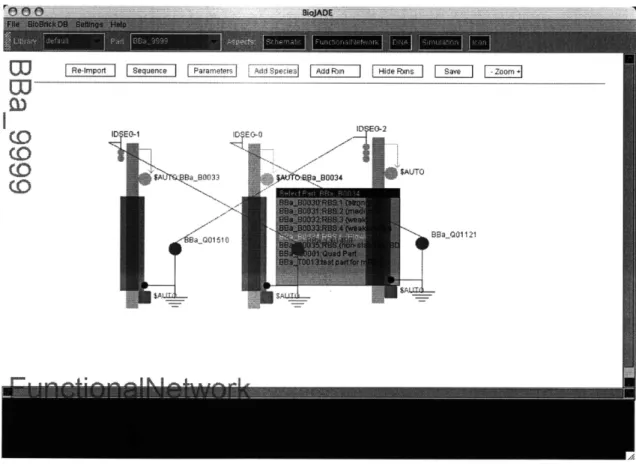
Fig. 4-5: The Functional Network Representation shows the same repressilator, but
in the form of stretches of DNA. System features such as ribosome binding sites can
be selected from the functional network aspect.
4.4.1
Adding Species and Reactions
In addition to the DNA itself, the Functional Network mode enables the designer to express other important reactions and processes such as protein and RNA degrada-tion rates, small molecule interacdegrada-tions, and anti-sense behaviors. These important interactions are not represented well a schematic, but are vital in expressing how a complicated system works.
To add a molecule, click on the Add Species button on the top of the window, a dialog will pop up and ask for the name of the species, and then the initial concen-tration and finally, the degradation rate.
Reactions between species (both manually inserted and the protein/RNA from the system) can be assembled by clicking on the Add Rxn button. The reaction will be represented as in FIG, with the two sides of the reaction, as well as forward and reverse rate constants. Clicking on each of these regions allows you to set the rate constants, or add other substrates or products. To add a substrate or product, click on the right, or left side of the <=>, respectively. Then click on the substrate or product of interest on the screen. The species is added to the reaction, and the system draws a line between the reaction and the species connected to it. These reactions will then be modeled and simulated in whatever simulator is later selected.
4.4.2
Refining Auto Part Selections
The compilation process of making a concrete part out of the abstract design gives designers some flexibility in deciding which parts to use for certain common features, such as ribosome binding sites and terminators. For biological and design reasons, it may be desirable to manually make choices based on efficiencies. In addition, select-ing different parts will reduce homology and thus reduce the likelihood of undesired
COD 50-0
IDPEO-$AUJTO
$UD B 1303 J 0032
-ltla00 i 0 89aQ01 400 aQC12
$A!
Meg8014-Save -Zoom +
Fig. 4-6: The Functional Network mode also enables the designer to specify other species and reactions that affect system performance. This figure shows a degradation reaction involving one of the signaling molecules.
recombination events.
To set these variable sequence features such as RBS's and terminators, the de-signer clicks on that section of the DNA segment and a window pops up with a list of available parts to assign to that module. Using the arrow keys, the user can scroll through the list of options and select the part that fits best in the system.
Once satisfied with the functional representation of the network, the next step in design is to simulate its function. For this feature, we utilize the Simulation Aspect
$A~ BaB0032 SAUTO
a8 B01031 Promoer Dtail
Fig. 4-7: Editing promoter details such as the cooperativity in the Functional Net-work mode.
to access a variety of simulators.
4.5
Simulation Aspect
The simulation aspect provides an interface to a variety of simulation tools using the D-FLUX protocol for performing intense computation on distributed computers. The designer can select one or more simulations to execute on the design.
system or just wait for the results. The simulation results are then displayed in what-ever viewer is appropriate for the simulation. Simulation results that are computed on remote systems may be retrieved and viewed at the designer's convenience. This asynchronicity affords the designer with more time to tinker with the system and see the impact small changes have on system characteristics. This feature should help to increase the productivity of BioJADE designers.
Chapter 5 is a more comprehensive discussion of the Simulation Aspect and the available simulations.
Fig. 4-8: The same repressilator simulated with Stochastirator. The figure shows the oscillation of all three signaling molecules.
4.6
Icon Aspect
No part is complete without its own graphical representation. Because we wanted to give the users flexibility in their choice of iconography, the user can draw a 50x50 pixel representation of their part in any paint program that exports to the
PNG/GIF/JPEG formats. The icon aspect allows the user to select the icon file,
which is then displayed. Once the graphical representation is selected, the designer selects Mark Terminals to mark the terminals of the device. When the part is used in a schematic view, the terminals provide places to attach wires.
Fig. 4-9: Drawing a dynamic terminal onto the icon representation for a wired-NOR gate. The red terminal is a normal terminal, and the green arc on the left is the dynamic terminal area.
Upon marking a terminal, BioJADE asks the designer what kind of terminal they are putting down: input, output or undefined. ALT-clicking on the terminal can change the choice at any time. In addition, Control-clicking allows the user to select an associated subpart of the device to which the terminal is connected.
4.6.1
Dynamic Terminals
Part of designing general devices includes adding the possibility of having variable numbers of terminals on the device. To account for this possibility, the icon aspect allows the designer to specify dynamic terminals, which define a strip of the device that can grow to an arbitrary number of terminals. To specify a dynamic terminal, click on the Add Dynamic Terminal button, and then click once on the start point for the dynamic terminal, as you drag your mouse across the icon, a line showing the dynamic terminal is shown. Holding down the shift key while dragging the mouse draws an arc shaped dynamic terminal. Clicking again sets the terminal's ending position. The actual number of terminals that implement the dynamic terminal is set by in the schematic mode after the components are stamped onto a design.
Parts that are simply an implementation of a part type (inverters, NANDs) need no special graphical representation of their own. The user can provide an icon, but the default representation for the part type is used instead if there is no icon selected.
4.7
DNA Aspect
DNA mode allows BioJADE users to view the basic DNA features of a part in a
format similar to other tools, such as the Biobricks Repository or Vector NTI. In addition, the DNA aspect gives the user a view and summary of the local DNA features such as GC content, the forward and reverse sequences and the cut sites of restriction enzymes. The DNA aspect shows two panes, one containing the DNA sequence and the other showing an annotation of the sequence. This feature is intended primarily to convey information rather than edit it.
Fig. 4-10: Examining the repressilator in the DNA Aspect. The DNA Aspect displays sequence data along with a graphical representation highlighting the annotation of the DNA.
Chapter 5
Simulations
An abstract design tool is far more useful when combined with powerful and accurate simulation tools. BioJADE includes a number of powerful simulation systems that enable desingers to understand and predict the behavior of their designs. BioJADE is very flexible in its simulation capabilities, offering a plug-in type architecture for wrapping almost any third-party simulator available.
5.1
D-FLUX
We utilize the Distributed, FLexible and User eXtensible protocol for simulations.
D-FLUX lets us implement a series of wrappers that encapsulate essentially any
simulator we desire. Simulators such as Tabasco [4] are written in Java, which allows us to directly call the necessary functions in the application. However, it is also possible to execute any script, or executable program on the host computer and thus we have access to any simulator that is commercially or freely available.
the simulation to any available simulation machine. This architecture gives the user access to much more powerful machines and, thus, more complicated simulations than they would be able to execute on their own machine. In addition, batches of simulations can be run on clusters of remote machines, permitting the designer to create a range of parameters to test.
5.1.1
The Architecture
Communication Protocol
The communication protocol is based on work done with developing a secure voting system. In this model, there is a client and a server. The server is the system that is waiting for requests and the client is the system that sends requests. The server listens for socket connections on a specified port. The client initiates a request, the server acknowledges the connection and spawns a process to handle it. At this point, the client merely sends an XML formatted command to the server, and the server generates the appropriate reply and writes it back to the client.
The communication protocol is fairly simple. Clients send messages to the server of the form <COMMAND><commandName/></COMMAND> .
The Server replies <RESULTS><result/></RESULTS>. Each command ends with a line with the string "!!!END!!!".
Available Commands are:
" GET-AVAILABLE-SERVICES - Returns the services that are available on the
server queried.
" EXECUTE (service, user, password, <params>,<data>) - Returns a pro-cess ID on the server to acpro-cess the status/results of the command.
" GET-STATUS (<processes>, <user>) -Returns the status of the list(s) of
pro-cesses or users.
" GET-RESULTS (process) - Returns the results from the simulation data in the
simulator's format.
Parameters noted in angle brackets are enclosed within the command's opening and closing tags as their own entities while unenclosed tags are passed as parameters within the command's opening tag. Note that by convention, all tags are capitalized, with all parameters lower case. All tags that do not have a closing tag must have a self-closure (/>). As usual with XML, white space is not important in non-quoted strings.
Exceptions are passed back as an <EXCEPTION> and they contain (optionally) the service, and then within the body of the tag, a text description of the error.
Simulation Server
The simulation server itself is highly simplistic. The specification merely requires that it provide appropriate responses for the basic commands. To fulfill this task, we implement the server as a thread spawning while loop. The server listens on its assigned port and whenever a request is received, it invokes a thread to handle the request. How to manage concurrency and the status of local processes are not ad-dressed in the protocol, but the server must keep track of the state of each simulation request. Connections are not held open, so clients must submit separate requests to check on the status and get results from their simulations.
For BioJADE, the simulation server transmits the results to the parts repository. That way, the results are available asynchronously to multiple investigators.
Simulator Address Server
The address server merely maintains a list of the available servers for simulations. Each entry contains the IP address or name of the server, the port number it listens on, and whether or not it requires authentication. The address server is structurally identical to the Simulator Server but it accepts a different set of commands.
" REGISTER-SERVICE (service-name, address port,
authentication)-reg-isters the specified service with the address server.
* GET-SERVICES - returns the services registered with the address server in the form <RESULTS><SERVICE name=' service-name ' address=' f rancis ' port='999'
authentication='public '></RESULTS>
The SAS provides a central place to store all of the services available, and enables an organization to maintain one or two SAS servers and not have to update every client when a new service is brought online.
5.2
Standard Simulators
5.2.1
Stochastirator
The Stochastirator is a Gibson-Modified-Gillespie [9, 18, 8, 19] simulator written by Eric Lyons in C++. Stochastirator is wrapped by writing out the necessary model definitions and parameters, and then executing the simulator.
Stochastirator is a stochastic simulator useful for dealing with systems at the sin-gle molecule level, rather than the concentration levels which are often used. Defining a system with BioJADE allows it to be simulated directly with Stochastirator.
The translation program takes in the design, and builds interactions between the species in the system, and the repressors they bind to. The translator also connects the promoter regions to the genes they promote (wired connections) by simulating the transcription and translation reactions that produce proteins. This process takes into account the cooperative binding of species, an effect that accounts for the non-linearity.
5.2.2
Tabasco
Tabasco, written by Sriram Kosuri and Jason Kelly [4], was originally designed to simulate the behavior of phage DNA entering a cell. The DFLUX Wrapper trans-lates the designer's DNA system into the tabasco format, and alters rate constants to simulate normal transcription and control. Tabasco simulates, with single-base resolution, the behavior of polymerases, small molecules, and proteins within the host cell.
Wrapping Tabasco in D-FLUX was the first practical application of D-FLUX. Writing the wrapper was simple because Tabasco is written in Java. Thus we are able to hook directly into the native data structures and simply execute the simulator. Since D-FLUX permits us to execute complicated simulations on (multiple) re-mote computers, a designer can build a matrix of different values that she wants to test the system with, submit that set of simulations to one or more compute clus-ters, and proceed to design another system while the remote cluster executes the simulations. She can then check the servers to see if the results are ready. If so, she downloads the data sets, and analyzes the data. In the case of Tabasco, this data can be viewed either as plain text values, or, more usefully, as a movie depicting the transcription of each gene. The DFLUX packaged version of Tabasco automatically
generates a quicktime movie out of the simulation data and stores it in the parts repository.
For example, suppose that we want to view the behavior of a simple ring oscillator. We can design the oscillator using the Schematic mode, specify the relevant values for constants, transfer curves, etc in the Functional Network mode, and then submit the simulation to Tabasco.
5.2.3
Electrical Models
The electrical type systems use electrical models for simulating the behavior of ge-netic regulatory systems. One such example is the Represstor [24] simulator written
by Gerald Jay Sussman in Scheme.
5.2.4
Logic and State Machines
A higher level simulation that is not yet implemented is a logic level simulation of the
behavior of the systems. Each type of device has a logic function associated with it, and this logic function, along with the layout of the system would allow the designer to test the system out with a variety of initialization parameters and observe the behavior.
Simulation Servers
Pat Dtbase
DFLUX
BioJADE Clients
Fig. 5-1: DFLUX gives designers shared access to powerful computational resources to execute simulations.
Fig. 5-2: A Tabasco simulation visualization that shows(in quicktime format) the generation of mRNAs and their associated proteins. The levels of each species is shown at the upper left corner. The DNA is shown as a line, with green blocks representing transcription starts, and yellow blocks representing termination. The blue or green ovals on top of the DNA are the polymerases, which move along the
DNA. Finally, below the DNA are lines and a number representing mRNA transcripts
Chapter 6
Modeling Biology and Devices
Having models of the world is useful and convenient, but we must have actual mea-sured data in order to make reasonable predictions about the behavior of a system. This chapter describes the models, parameter measurement and designer interac-tions that allow BioJADE to execute simulainterac-tions that provide useful insights into their behavior. BioBricks, while they encapsulate the basic part and interaction, do not include all of the information necessary to simulate systems. Device models encapsulate the general design of devices instead of just functional DNA segments. In addition, device models provide a more comprehensive means of providing data to simulate their behavior.
6.1
Basic Models
6.1.1
General Treatment of Cellular Species
There is a lot of "stuff" floating around in cells, and we really have no good way of knowing exactly how all of the species in the cell interact with each other, as well as

![Fig. 2-6: An overview of the Standard Assembly Process [14, 26]. This diagram shows the idempotent assembly procedure where the output from one cycle is an input into the next.](https://thumb-eu.123doks.com/thumbv2/123doknet/14162934.473497/24.918.197.834.343.653/overview-standard-assembly-process-diagram-idempotent-assembly-procedure.webp)