Publisher’s version / Version de l'éditeur:
Journal of Architectural Engineering, 12, December 4, pp. 168-177, 2006-12-01
READ THESE TERMS AND CONDITIONS CAREFULLY BEFORE USING THIS WEBSITE.
https://nrc-publications.canada.ca/eng/copyright
Vous avez des questions? Nous pouvons vous aider. Pour communiquer directement avec un auteur, consultez la
première page de la revue dans laquelle son article a été publié afin de trouver ses coordonnées. Si vous n’arrivez pas à les repérer, communiquez avec nous à PublicationsArchive-ArchivesPublications@nrc-cnrc.gc.ca.
Questions? Contact the NRC Publications Archive team at
PublicationsArchive-ArchivesPublications@nrc-cnrc.gc.ca. If you wish to email the authors directly, please see the first page of the publication for their contact information.
NRC Publications Archive
Archives des publications du CNRC
This publication could be one of several versions: author’s original, accepted manuscript or the publisher’s version. / La version de cette publication peut être l’une des suivantes : la version prépublication de l’auteur, la version acceptée du manuscrit ou la version de l’éditeur.
For the publisher’s version, please access the DOI link below./ Pour consulter la version de l’éditeur, utilisez le lien DOI ci-dessous.
https://doi.org/10.1061/(ASCE)1076-0431(2006)12:4(168)
Access and use of this website and the material on it are subject to the Terms and Conditions set forth at
New design procedure for wind uplift resistance of architectural metal
roofing systems
Baskaran, B. A.; Ham, H. J.; Lei, W.
https://publications-cnrc.canada.ca/fra/droits
L’accès à ce site Web et l’utilisation de son contenu sont assujettis aux conditions présentées dans le site LISEZ CES CONDITIONS ATTENTIVEMENT AVANT D’UTILISER CE SITE WEB.
NRC Publications Record / Notice d'Archives des publications de CNRC:
https://nrc-publications.canada.ca/eng/view/object/?id=9e092c80-f17e-4bb5-89dc-c96ccb794c10 https://publications-cnrc.canada.ca/fra/voir/objet/?id=9e092c80-f17e-4bb5-89dc-c96ccb794c10http://irc.nrc-cnrc.gc.ca
N e w de sign proc e dure for w ind uplift
re sist a nc e of a rchit e c t ura l m e t a l roofing
syst e m s
N R C C - 4 8 1 3 3
B a s k a r a n , A . ; H a m , H . ; L e i , W .
A version of this document is published in / Une version de ce
document se trouve dans: Journal of Architectural Engineering, v.
12, no. 4, Dec. 2006, pp. 168-177 doi:
New Design Procedure for Wind Uplift Resistance
of Architectural Metal Roofing Systems
1
A. Baskaran
2; H. Ham
3; and W. Lei
4Abstract: Currently, there are no Canadian national guidelines for the wind uplift resistance of architectural metal roof systems. Thus,
it is difficult to judge their suitability and performance based on a common standard. Given the increasing use of metal roofs, it has been determined that there is a need for the development of a design guide, that would be applicable to all regions of Canada. Metal roofs can be classified into two groups: Structural and architectural. This paper focuses on the wind uplift performance of architectural metal roof systems. Several parameters influence the wind uplift performance of the architectural metal roofs. This study finds that air leakage of the structural deck is one of the significant factors that influences the wind uplift performance. This is based on experimental investigations carried out at the Dynamic Roofing Facility of the National Research Council of Canada, using the Special Interest Group on Dynamic Evaluation of Roofing System dynamic wind test protocol. Architectural roofing panels with three different types of commonly used, seam-interlocking mechanisms 共joint details兲 were investigated. It has been noted that the resistance to wind uplift pressure increases dramatically as the air leakage ratio decreases. A modeling method is also described which quantifies system response by simulating the wind gusts over roof specimens with different leakage ratios that can represent field assemblies. The 1995 National Building Code of Canada was utilized for the estimation of the wind-induced loads and the present study provided extensive experimental data for various systems with each type of seam detail. Based on this analysis, a simplified design procedure was developed. The simplified procedure is presented through case studies of metal roof assemblies located in the Canadian provinces of British Columbia, Ontario, and Quebec.
DOI: 10.1061/共ASCE兲1076-0431共2006兲12:4共168兲
CE Database subject headings: Roofs; Metals; Dynamic tests; Leakage; Building codes; Design criteria.
Introduction
Use of metal as a waterproofing roofing material goes way back to the Roman Empire. In the early 1800s roofers started experi-menting with tinplate, which was less expensive than the other materials such as copper, zinc, etc. With more experimental re-search done, in the mid-1900s corrugated, galvanized, metal sheets were mass produced and became a popular alternative to tinplate for industrial, agricultural, and commercial roofing. Gen-erally, metal roofs can be categorized into two main categories: Structural and architectural. The structural panels are used on low-sloped roofs and are installed directly on the purlins. In those scenarios the panels perform both the structural and
waterproof-ing functions of a roof. The most common structural panels are the standing seam panels that are used on nonresidential build-ings. The architectural metal roofing panels are installed mainly on steeply pitched roofs, generally on a minimum slope of 3:12 共ratio of vertical to horizontal兲 to ensure proper water run-off. Installations of the composite roof assemblies are quite different from the structural systems. The architectural panels are installed over a wood or steel deck or, in some applications, directly over an existing roof.
Metal panels installed on a roof are subjected to various levels of wind dynamics during their lifetime. Wind-induced dynamic effects cause the panels to deflect and introduce stresses at the attachment locations. Fig. 1 illustrates the interaction of the wind with the metal panels. As shown in Fig. 1, the metal panels are placed as rooftop cover and attached to the wooden deck with a variety of clip attachments. The metal panels are joined by differ-ent types of locking mechanisms. Wind-induced suction lifts the metal panel between the seams 共joints兲. The magnitude of the wind-induced suction and the type of metal panel attachment de-termines the wind uplift resistance of the system. Also as shown in Fig. 1, each component offers certain resistance to wind uplift force and this can be represented through a force resistance link diagram 共i.e., a load path diagram兲. All resistance links should remain connected for the roofing system to stay in place. Failure occurs when the wind uplift force is greater than the resistance of one or more of the resistance links.
International provisions 关North American specification 共ANSI 2001; ASTM 2002兲, European provisions 关EUROCODE3 Commis-sion of the European Communities 共1992兲兴, and Australian 共AS/ NZS 1996兲兴 are mainly focused on the fixing 共attachment兲
mecha-1
Presented at the 11th International Wind Engineering Conference, June 2003, Texas Tech University, Lubbock, TX.
2
Group Leader and Senior Research Officer, National Research Council Canada, Institute for Research in Construction, 1200 Montreal Rd., Ottawa ON, Canada K1A 0R6.
3
Formerly, Visiting Research Fellow, National Research Council Canada, Institute for Research in Construction, 1200 Montreal Rd., Ottawa ON, Canada K1A 0R6.
4
Technical Officer, National Research Council Canada, Institute for Research in Construction, 1200 Montreal Rd., Ottawa ON, Canada K1A 0R6.
Note. Discussion open until May 1, 2007. Separate discussions must be submitted for individual papers. To extend the closing date by one month, a written request must be filed with the ASCE Managing Editor. The manuscript for this paper was submitted for review and possible publication on January 19, 2005; approved on October 10, 2005. This paper is part of the Journal of Architectural Engineering, Vol. 12, No. 4, December 1, 2006. ©ASCE, ISSN 1076-0431/2006/4-168–177/$25.00.
nisms of the structural roofing systems. A number of researchers have investigated the structural performance of metal roofs under static conditions 共Mahendran 1990, 1997; Meyers et al. 1990; Schroter 1985兲. Currently there are no national or international guidelines or standards for the wind uplift resistance of architec-tural sheet metal roofing systems. Thus, it is difficult to assess the performance of an architectural metal roofing system based on an accepted design method for determining wind uplift resistance. Given the increasing use of architectural metal as roof covers 关market shares are up from 3 to 7% 共Cullen 1993兲兴, there is a need to develop a technical guide for the wind resistance of ar-chitectural metal roof systems that would be applicable to all regions of Canada.
This paper presents the research work being carried out for the development of an overall test method and design procedure for evaluating the wind uplift resistance of architectural metal roofing systems. A modeling method is also described that quantifies sys-tem response by simulating the wind gusts over roof specimens with different leakage ratios that can represent field assemblies. The National Building Code of Canada 共NRC 1995兲 was utilized for the estimation of the wind-induced loads and the present study provided extensive experimental data for system resistance data. Based on this analysis, a simplified design procedure was devel-oped. The simplified procedure is presented through case studies of architectural metal roof assemblies located in the provinces of British Columbia, Ontario, and Quebec.
Experimental Approach
Dynamic Roofing Facility
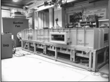
All experimental work for the present investigations was carried out at the Dynamic Roofing Facility 共DRF兲 established at the National Research Council of Canada 共NRC/IRC兲. The DRF is shown in Fig. 2 and the features of the facility are provided by Baskaran and Lei 共1997兲. The DRF consists of a bottom frame of adjustable height, upon which the roof specimens are installed, and a movable top chamber. The bottom frame and top chamber are 6,100 mm 共240 in.兲 long, 2,200 mm 共86 in.兲 wide and 800 mm 共32 in.兲 in height. Wind suctions as high as 20 kPa 共⬇420 psf兲 over the roof assembly are produced by a 75 kW 共100 HP兲 fan with a flow rate of 2,500 L / s 共5,300 cfm兲. A com-puter uses feedback signals to control the operation of the DRF.
To monitor the response of the roof system, typical design param-eters such as pressure, force, and deflection were measured.
Dynamic Wind Test Protocol
A Special Interest Group for Dynamic Evaluation of Roofing Sys-tems 共SIGDERS兲 has been established at the NRC to develop a test standard for evaluating roofing systems under dynamic con-ditions. The SIGDERS dynamic load cycle was developed based on extensive wind tunnel studies. The procedure used for the development of the wind loading sequence can be found in Baskaran et al. 共1999兲. The dynamic load cycle represented in Fig. 3 includes eight loading sequences in which a roof system is subjected to simulated gusts. To evaluate the ultimate strength of the roofing system, testing begins at Level A which uses a maxi-mum test pressure of 90 psf. If all the resistance links 共Fig. 1兲 remain connected, the roof is considered to have “passed” and obtains Level A rating. Testing then proceeds to the next level, where the maximum pressure is increased by 25% of Level A’s maximum test pressure 共see Fig. 3兲. For all the investigations in this study, this dynamic load cycle was applied.
Experimental Investigations
Investigated Panel Configurations
Twenty metal panel roofing systems having three different inter-locking mechanisms were investigated. Details of the experimen-tal procedure and system response for various induced loading conditions are documented by Ham and Baskaran 共2000, 2001a兲. Only salient features are highlighted below. Cross-sectional rep-resentations of a typical test assembly and details of the three different attachment mechanisms are shown in Fig. 4.
• SNAP LOCK 2: Fig. 4共a兲 shows details of the panel edges, which consist of a male leg on one side and a female flange on the other. The male rib height is 44 mm 共1 3 / 4 in.兲 and width of panel is 457 mm 共18 in.兲. The male leg of the panel is attached to the deck with Clert Series 2000 clips. The clip is 44 mm 共1 3 / 4 in.兲 high, 89 mm 共3 1 / 2 in.兲 long and 38 mm 共1 1 / 2 in.兲 wide. Two No. 12⫻1 in. pancake head fasteners were used per clip to attach the panels to the deck. The spacing of the clip varied from 457 to 610 mm 共from 18 to 24 in.兲
Fig. 1. Wind effects on metal roofing systems
depending on the system tested. Once the male leg is attached, the female leg of the adjacent panel is placed over the male leg and the two legs snap together to provide the interlocking joint mechanism.
• KR-12: Fig. 4共b兲 illustrates the KR-12 panel, which has a rib height of 38 mm 共1 1 / 2 in.兲. Within the locking mechanism, the KR-12 panel is attached to the deck using the KR-12 lock clip, which has dimensions of 38 mm 共1 1 / 2 in.兲 height, 159 mm 共6 1 / 4 in.兲 length, and 25 mm 共1 in.兲 width. Two No. 12⫻ 1 in. fasteners are used per clip to attach the panel to the deck. The clip spacing is 305 mm 共12 in.兲, 457 mm 共18 in.兲, or 610 mm 共24 in.兲, depending on the system tested. The edge of another panel is then engaged with the previously anchored edge of the first panel and a mechanical seaming machine locks the seam securely.
• PROLOCK: Fig. 4共c兲 depicts the locking mechanism, which consists of a female flange of 27 mm 共1 1 / 16 in.兲 height and a male rib of 38 mm 共3 / 4 in.兲 height. The male rib of the panel is attached to the deck using Phillips head No. 8 ⫻ 1 in. fas-teners. These fasteners are placed at a spacing of 342 mm 共13 1 / 2 in.兲 along the male side of the panel’s fastening flange. The female flange is then aligned over the male rib and, by using a rubber hammer, the female edge is snapped onto the
male edge, thus engaging the edges of adjacent panels.
Simulated Deck Conditions
The performance of a metal roofing system under wind loading can be influenced by several factors, with air tightness of the deck being one of the most important parameters. The air tightness of the deck was represented in terms of the air leakage ratio, which is defined as the ratio of the leakage area to the deck area. Addi-tional details of the air leakage calculations can be found in Ham and Baskaran 共2001b兲. In the present study, the air tightness of the deck was investigated by simulating three groups of deck condi-tions, namely:
• Group 1: Airtight Deck Condition: The airtight deck condi-tion was simulated by using five sheets of 16 mm 共5 / 8 in.兲 tongue-and-groove plywood sheets installed over 51 mm ⫻ 254 mm 共2 in.⫻ 10 in.兲 joists, as shown in Fig. 5.
• Group 2: Air Permeable Deck Condition: Different air leak-age ratios were simulated as follows:
1. Field conditions were simulated by using the H-clip at-tachment in between the plywood deck sheets. These sheets, 13 mm 共1 / 2 in.兲 thick, were installed over the 51 mm⫻ 254 mm 共2 in.⫻ 10 in.兲 joists. The spacing
tween the plywood sheets, created by the H clips, pro-vided the pathway for airflow.
2. The air leakage path created by the H clips was further blocked by applying caulking strips at preferential loca-tions, thereby reducing the air leakage ratio.
3. Using tongue-and-groove plywood deck and making 12 mm 共1 / 2 in.兲 diameter holes in the wooden deck. 4. Using 12 mm 共1 / 2 in.兲 plywood deck and fastening the
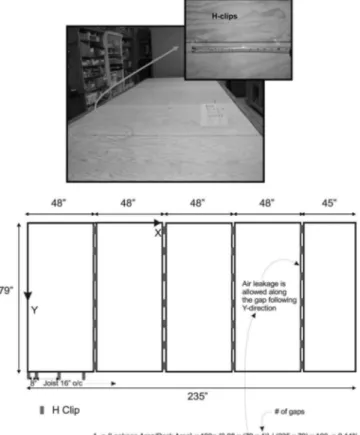
sheets to 51 mm⫻ 203 mm 共2 in.⫻ 8 in.兲 joists and mak-ing square holes of 100 mm 共4 in.兲 wide in the deck. A typical layout of an air-permeable deck condition with air leak-age ratio, AL, of 0.14% is shown in Fig. 6. As can be seen from the layout, 5 pieces of 12 mm 共1 / 2 in.兲 plywood were used in the deck arrangement. H clips were used between the plywood sheets in such a way that there were two gaps of 2 mm 共0.08 in.兲 be-tween the plywood attachments. Air leakage is allowed along
these gaps. The sample calculation for air leakage ratio is also given in Fig. 6.
• Group 3: Air Permeable Deck Condition With
Underlay-ment: As shown in Fig. 7, either peel-and-stick sheets or No. 30 organic saturated felt papers were used as an underlayment between the wooden deck and metal panels. Within this group, the air leakage ratios ranging from 0.08 to 0.18% were simu-lated and investigated.
Results and Discussion
As mentioned, 20 experiments 共Systems 1–20兲 were done using the three different panel types and simulating various leakage conditions of the deck. For most of the systems, more than one
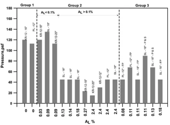
specimen was investigated. The calculated leakage ratios for each system configuration and the corresponding panel type are sum-marized in Table 1. For each system configuration, sensors were installed at selected locations, to measure the system’s response during wind testing. Time histories of the applied pressure and induced load on the fasteners, as well as the deflection of the panel, were collected and analyzed 共Ham and Baskaran 2000, 2001a兲. The data obtained from different configurations are sum-marized in three groups as shown in Fig. 8. It is evident that the air leakage of the deck is one of the significant factors for influ-encing the wind uplift rating of the system.
1. In Group 1, it was observed that for the airtight deck condi-tions 共AL= 0 % 兲, the KR-12 metal panel showed a better wind uplift resistance when compared to the PROLOCK metal panel system. The measured load on the KR-12 metal panel system was high compared to the PROLOCK system and this may be attributed to the wider 共406 mm compared to 305 mm兲 panel size of the KR-12 metal panel system. With constant clip attachment spacing as panel width increases,
the tributary area increases as such the panel resistance to load decrease.
2. In Group 2, the data can be divided into two sets,
AL⬍ 0.1% and AL⬎ 0.1%. For the first set of AL⬍ 0.1%, the
tested systems behaved more like the systems in Group 1 共airtight deck conditions兲 with all metal roofing systems ex-hibiting high wind uplift resistances which were in excess of 4,788 Pa 共100 psf兲. However, a variation in the measure loads was observed. In the second set, with AL⬎ 0.1%, it is evident that there are dramatic decreases in the wind uplift rating when the AL ratio increases from 0.1% to higher
val-ues. All these systems failed below 2,154 Pa 共45 psf兲 and the measured failure load decreased with the increase of ALratio for the same panel type.
3. In Group 3, the main objective was to see the influence of the underlayment on the systems having air leakage. It was ob-served that systems with peel-and-stick as underlayment per-formed better than systems with felt paper as underlayment. The performance of systems with peel-and-stick as
ment were similar to the airtight configuration in achieving wind uplift rating. Nevertheless, once again the leakage ratio played a major role in influencing the wind uplift resistance. It appears from this data that despite differences in the panel configuration or other parameters, a significant effect on the wind uplift rating results from differences in air leakage ratio
AL.
Failure modes of the systems were also investigated after the wind test. Typically, three different failure mechanisms were ob-served according to the three different deck conditions 共Baskaran and Ham 2003兲. Systems from the Group 1 with airtight deck conditions failed because the net load on the deck exceeded the strength of the deck-to-joist connection. In other words, the fas-tener attachment of the deck pulled out from the joist. In the case of the Group 2 systems with an air-permeable deck condition,
panel seams opened or separated during wind testing. The weak-est link of this group is the seam-locking mechanism of the metal panels. For the Group 3 configurations with felt papers as under-layment, the observed failure mechanism was panel fastener pull-out from the wooden deck and tearing of the underlayment. This preliminary failure triggered the panel seam opening as a second-ary failure. Although the Group 3 systems with peel-and-stick as underlayment also had the same failure mechanism, in addition deck pullout from the joist was also observed in one system.
Simplified Design Procedure
Currently there are no Canadian guidelines for the wind uplift resistance of metal roof systems. One of the main objectives of the present experimental investigation is the development of a simplified design procedure that can be used by practicing engi-neers. The proposed simplified procedure uses the National Build-ing Code of Canada 共NRC 1995兲 for wind uplift load calculation, experimental information as resistance data, engineering direc-tives, and inputs from industrial clients for case study formula-tion. Moreover, the development of a simplified procedure requires several levels of generalization of the true wind-induced effect over a roof assembly. Often, these generalizations warrant compromise from the technically sound approach to the practi-cally acceptable procedure. Similar simplified design procedures developed in the past 共Kind and Wardlaw 1976兲 for ballasted roof assemblies were received well by all parties concerned with roof-ing, including researchers, manufacturers, roofing associations representing the contractors, and building owners. As presented, the procedure is applicable to three provinces of Canada 共British Columbia, Ontario, and Quebec兲 and it can be extended to other provinces on as-needed basis. It is a five-step procedure as follows:
1. Calculate roof cover design pressure; 2. Estimate wind uplift design pressure;
3. Select reduction factor for air permeable deck conditions; 4. Identify a suitable system with required resistance; and 5. Correlate uplift pressure with resistance.
Step 1: Calculate Roof Cover Design Pressure
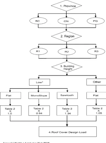
The roof cover design pressure calculation is shown as a flow-chart in Fig. 9. As shown, first the designer identifies the province and region in that province for the location of the building using Fig. 10. Then based on the building height, design suction
pres-Fig. 6. Typical layout of the air permeable deck condition and
calculation of leakage ratio
Table 1. Summary of the Tested Assemblies and Wind Uplift Ratings
Panel width Clip spacing
Sustained clip fastener load
Sustained uplift pressure
Group System Panel type/name AL共%兲 共mm兲 共in.兲 共mm兲 共in.兲 共N兲 共lbf兲 共Pa兲 共psf兲
Failure mode 1 1 KR-12 0 406 16 610 24 1,848 420 5,746 120 FM1 2 2 KR-12 0.03 457 18 610 24 1,408 320 5,746 120 FM2 2 3 KR-12 0.09 508 20 457 18 686 156 5,410 113 FM2 2 4 KR-12 0.27 457 18 457 18 224 51 1,101 23 FM2 2 5 KR-12 2.4 508 20 508 20 356 81 718 15 FM2 2 6 KR-12 2.4 305 12 305 12 656 149 1,436 30 FM2 2 7 KR-12 2.4 305 12 305 12 — — 2,155 45 FM2 1 8 PROLOCK 0 305 12 305 12 1,540 350 5,410 113 FM1 2 9 PROLOCK 2.4 305 12 305 12 774 176 2,155 45 FM2 3 10 PROLOCK-F 0.08 305 12 305 12 330 75 2,155 45 FM3 3 11 PROLOCK-F 0.11 305 12 305 12 726 165 3,256 68 FM3 2 12 SNAP LOCK 2 0.09 457 18 457 18 1,056 240 6,464 135 FM2 2 13 SNAP LOCK 2 0.13 457 18 457 18 585 133 2,155 45 FM2 2 14 SNAP LOCK 2 0.14 457 18 457 18 554 126 2,155 45 FM2 2 15 SNAP LOCK 2 0.18 457 18 457 18 427 97 2,155 45 FM2 2 16 SNAP LOCK 2 2.4 457 18 457 18 1,012 230 2,155 45 FM2 3 17 SNAP LOCK 2-F 0.11 457 18 305 18 554 126 2,155 45 FM3 3 18 SNAP LOCK 2-F 0.18 457 18 305 18 563 128 2,155 45 FM3 3 19 SNAP LOCK 2-S 0.11 457 18 305 18 532 121 4,309 90 FM3 3 20 SNAP LOCK 2-S 0.13 457 18 305 18 712 162 3,256 68 FM3
Note: F⫽felt paper; S⫽self-adhered membrane; FM1⫽deck-to-joist connection failure; FM2⫽panel delamination due to failure of seam-locking mechanism; and FM3⫽fastener pullout from the deck and tearing of the underlayment.
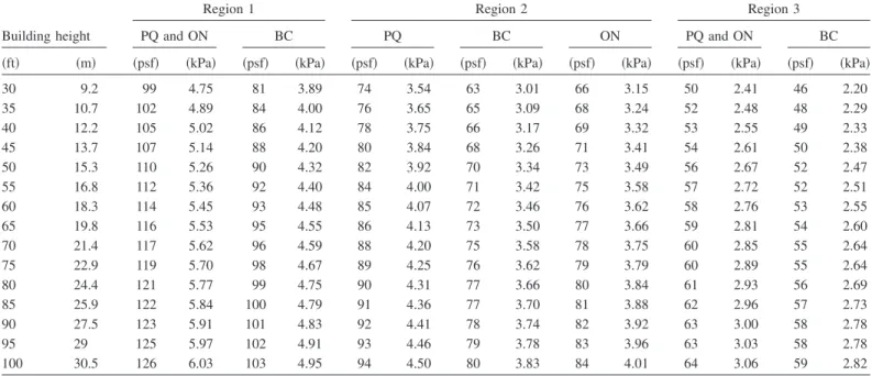
sures can be obtained from Table 2. Suction pressures reported in Table 2 are calculated in accordance with the National Building Code of Canada NRC 共1995兲 and its Part 4 user guide. As it is a standardized procedure, details are not documented in this paper and can be found elsewhere 共Baskaran and Smith 2005兲. During the present design procedure the following assumptions are made: 1. Building is designed to provide postdisaster services;
2. Low-rise buildings are defined as buildings with height-to-width ratios less than 1.0 and a reference height less than 20 m;
3. Roof types are defined based on slope as shown in the Steps 1.1–1.4;
4. Dynamic pressures, q, for the design of claddings, are based on 1/10 probability and are taken from the Appendix C of the NBCC 共NRC 1995兲;
5. Pressure coefficients are selected assuming a corner area of 1 m2using the Figs. 13共a and b兲 of the NBCC; and
6. Uniform Internal pressure conditions are assumed.
Based on the previous assumptions, calculations are performed by running a macro in the Microsoft EXCEL program. Computed cladding pressures are superimposed using a map viewer program to identify the three different regions for each of the province. Multiplication factors were calculated such that all three prov-inces can be classified into a common three different wind re-gions.
• Step 1.1: Low-rise building with flat roof 共less than 3°兲
Cladding design pressure
⫽suction pressure reported in Table 2
• Step 1.2: Low-rise building with monoslope roof 共greater than 3° and less than 10°兲
Cladding design pressure
⫽0.94⫻suction pressure reported in Table 2
• Step 1.3: Low-rise building with saw tooth roof 共greater than 10° and less than 30°兲
Cladding design pressure
⫽1.34⫻suction pressure reported in Table 2 • Step 1.4 Other buildings with flat roof
Cladding design pressure
⫽1.05⫻suction pressure reported in Table 2
Step 2: Estimate Wind Uplift Design Pressure
Wind uplift pressure⫽cladding design pressure⫻ factor of safety.
Building codes and wind standards recommend minimum design values. Selecting an appropriate factor of safety depends on the designer, and it should be 1.0 or higher. Note that at present, in the roofing industry the safety factor ranges from 2.0 to 4.0
de-Fig. 9. Flowchart showing the steps involved in the calculation of the
roof cover design load
pending on the selection of the components. This can account for any variation in the local exposure condition or roofing system behavior or to reduce the risk factor for the assumptions made in Step 1 or to have a design pressure beyond the code requirement.
Step 3: Select Reduction Factor for Air Permeable Deck Conditions
• Step 2.1: Calculate the ratio of leakage area by using the fol-lowing formula:
AL= 兵leakage area/deck area 其 ⫻ 100 (%)
• Step 2.2: Select a reduction factor from Fig. 11 to fulfill the following criteria:
Reduction factor ⱕ 1.0
Based on the input received from the industrial partners by taking
several practical deck layout conditions, a procedure for calculat-ing AL was documented 共Ham and Baskaran 2001b兲. A sample calculation is also shown in Fig. 8. For example, in conventional deck constructions, i.e., new 16 mm 共5 / 8 in.兲 tongue-and-groove plywood has AL⬵ 0%. When a 13 mm 共1 / 2 in.兲 thick plywood
deck was installed with H clips, ALcan be varied based on roof dimension, number of boards used, and clip locations. When deck construction permits air leakage through openings or joints, there will be significant reduction in the wind uplift resistance of the roof covering.
The reduction factor curve, shown in Fig. 11, to account for the air permeable deck construction has been developed based on experimental data and modeling. The horizontal axis shows the
AL as a percentage and the vertical axis displays the reduction
factor. It can be observed that the resistance to wind uplift pres-sure increases dramatically as the air leakage ratio decreases. It can also be estimated that a critical zone exists where the ultimate capacity changes dramatically 共0.12% ⱕ ALⱕ 0.27% 兲. For air
leakage zone, Z1 共0.0% ⱕALⱕ 0.09%兲, all tested metal panel
systems can be used with any underlayment. For air leakage zone, Z2 共0.09% ⱕALⱕ 0.13%兲, SNAP LOCK 2 共with panel width
smaller and equal to 18 in.兲 and PROLOCK 共with panel width smaller and equal to 12 in.兲 metal panel systems can use a self-adhered air barrier as underlayment. For air leakage zone, Z3 共AL⬎ 0.13% 兲, all metal panel systems should use self-adhered air barrier as underlayment for better wind uplift resistance.
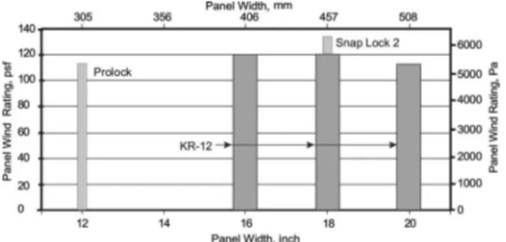
Step 4: Identify a Suitable System with Required Resistance
Using Fig. 12, select a panel configuration and its wind uplift rating. This rating represents a nonconservative scenario of metal coverings installed over an airtight deck configuration. Therefore, multiply by a reduction factor 共calculated in the Step 3兲 to obtain the wind uplift resistance of the system.
Wind uplift resistance⫽panel wind uplift rating⫻reduction factor
Step 5: Correlate Uplift Pressure with Resistance
Wind uplift resistance ⬎ wind uplift pressure Step 4 ⬎ Step 2
Table 2. Flat Roof Suction Design Pressures
Region 1 Region 2 Region 3
Building height PQ and ON BC PQ BC ON PQ and ON BC
共ft兲 共m兲 共psf兲 共kPa兲 共psf兲 共kPa兲 共psf兲 共kPa兲 共psf兲 共kPa兲 共psf兲 共kPa兲 共psf兲 共kPa兲 共psf兲 共kPa兲
30 9.2 99 4.75 81 3.89 74 3.54 63 3.01 66 3.15 50 2.41 46 2.20 35 10.7 102 4.89 84 4.00 76 3.65 65 3.09 68 3.24 52 2.48 48 2.29 40 12.2 105 5.02 86 4.12 78 3.75 66 3.17 69 3.32 53 2.55 49 2.33 45 13.7 107 5.14 88 4.20 80 3.84 68 3.26 71 3.41 54 2.61 50 2.38 50 15.3 110 5.26 90 4.32 82 3.92 70 3.34 73 3.49 56 2.67 52 2.47 55 16.8 112 5.36 92 4.40 84 4.00 71 3.42 75 3.58 57 2.72 52 2.51 60 18.3 114 5.45 93 4.48 85 4.07 72 3.46 76 3.62 58 2.76 53 2.55 65 19.8 116 5.53 95 4.55 86 4.13 73 3.50 77 3.66 59 2.81 54 2.60 70 21.4 117 5.62 96 4.59 88 4.20 75 3.58 78 3.75 60 2.85 55 2.64 75 22.9 119 5.70 98 4.67 89 4.25 76 3.62 79 3.79 60 2.89 55 2.64 80 24.4 121 5.77 99 4.75 90 4.31 77 3.66 80 3.84 61 2.93 56 2.69 85 25.9 122 5.84 100 4.79 91 4.36 77 3.70 81 3.88 62 2.96 57 2.73 90 27.5 123 5.91 101 4.83 92 4.41 78 3.74 82 3.92 63 3.00 58 2.78 95 29 125 5.97 102 4.91 93 4.46 79 3.78 83 3.96 63 3.03 58 2.78 100 30.5 126 6.03 103 4.95 94 4.50 80 3.83 84 4.01 64 3.06 59 2.82
Concluding Remarks
This paper has documented that air permeability of the structural deck is an important factor that affects the wind uplift perfor-mance of architectural metal roofing systems. Application of a self-adhered, modified bituminous underlayment improves the wind uplift performance. A modeling method is described which quantifies system response with different leakage ratios that can represent field assemblies. The National Building Code of Canada 共NRC 1995兲 was utilized for the estimation of the wind-induced loads and the present study provided extensive experimental data for various systems. Based on this analysis, a simplified design procedure was developed. The simplified procedure was pre-sented through case studies of architectural metal roof assemblies located in the provinces of British Columbia, Ontario, and Que-bec. The presented data was limited to metal roofing systems installed over wooden decks. Investigations are in progress for composite metal roof assemblies over steel deck.
Acknowledgments
This was a joint research project between Roofing Contractors Association of British Columbia 共Mr. Jim Watson兲 and NRC/IRC. The writers appreciate the contribution of Mike Sexton, Technical Officer at NRC and Suda Molleti, Industrial Research Fellow from Soprema, Canada.
References
American Iron and Steel Institute 共ANSI兲. 共2001兲. Specification for the
design of cold–formed steel structural members, Washington, D.C.
American Society for Testing and Materials 共ASTM兲. 共2002兲. “Tests for structural performance of sheet metal roof and sliding system by uni-form air pressure difference.” ASTM E 1592, Annual Book of ASTM Standards, Philadelphia.
Baskaran, A., Chen, Y., and Vilaipornaswai, U. 共1999兲. “A new dynamic wind load cycle to evaluate flexible membrane roofs.” J. Test. Eval.,
27共4兲, 249–265.
Baskaran, A, and Ham, H. 共2003兲. “Design guidelines for the wind uplift resistance of architectural metal roofing systems.” Proc., 11th Int.
Conf. on Wind Engineering, Texas Tech University, Lubbock, Tex. Baskaran, A., and Lei, W. 共1997兲. “A new facility for dynamic wind
performance evaluation of roofing systems.” Proc., 4th Int. Symp. on
Roofing Technology, NRCA/NIST, Washington, D.C., 168–179. Baskaran, A., and Smith, T. L. 共2005兲. A guide for the wind design of
mechanically attached flexible membrane roofs, SIGDERS Publica-tion, National Research Council of Canada, Ottawa.
Commission of the European Communities. 共1992兲. “Design of steel structures—Part 1.3—Cold framed thin gauge members and sheet-ing.” EUROCODE 3, Brussels, Belgium.
Cullen, W. C. 共1993兲. Project pinpoint analysis: Ten-year performance
experience of commercial roofing 1983–1992, U.S. National Roofing Contractors Association.
Ham, H., and Baskaran, A. 共2000兲. “Wind uplift resistance of metal roof—Phase I.” NRC Client Rep. No. B1040.1.
Ham, H., and Baskaran, A. 共2001a兲. “Wind uplift resistance of metal roof—Phase II.” NRC Client Rep. No. B1040.2.
Ham, H. J., and Baskaran, A. 共2001b兲, “Wind uplift resistance of archi-tectural metal roofing system.” Proc., Int. Conf. on Building Envelope
Systems and Technology (ICBEST)Ottawa, 31–38.
Kind, R. J., and Wardlaw, R. L. 共1976兲. “Design of rooftops against gravel blow-off.” National Aeronautical Establishment Rep. No.
15544, National Research Council Canada, Ottawa.
Mahendran, M. 共1990兲. “Fatigue behavior of corrugated roofing under cyclic wind loading.” Civil Engineering Trans, Canberra, Australia,
32共4兲, 219–226.
Mahendran, M. 共1997兲. “Review of current test methods for screwed connection.” J. Struct. Eng., 123共3兲, 321–325.
Meyers, L. R., Kozikol, S. R., Johnson, K. D., and Krogstad, V. N. 共1997兲. “Laboratory testing of low slope standing seam metal roof application.” Proc., 4th Int. Symp. on Roofing Technology, NRCA/ NIST, Washington, D.C., 144–152.
National Research Council of Canada 共NRC兲. 共1995兲. National Building
Code of Canada, Ottawa.
Schroter, R. C. 共1985兲. “Air pressure testing of sheet metal roofing.”
National Symp. on Roofing Technology, NRCA/NIST, Washington, D.C., 254–260.
Standards Australia 共AS/NZS兲. 共1996兲. “Cold formed steel structures code.” AS/NZS4600, Sydney, Australia.