Publisher’s version / Version de l'éditeur:
Professional Roofing, 36, August 8, pp. 38-42, 2006-08-01
READ THESE TERMS AND CONDITIONS CAREFULLY BEFORE USING THIS WEBSITE.
https://nrc-publications.canada.ca/eng/copyright
Vous avez des questions? Nous pouvons vous aider. Pour communiquer directement avec un auteur, consultez la première page de la revue dans laquelle son article a été publié afin de trouver ses coordonnées. Si vous n’arrivez pas à les repérer, communiquez avec nous à PublicationsArchive-ArchivesPublications@nrc-cnrc.gc.ca.
Questions? Contact the NRC Publications Archive team at
PublicationsArchive-ArchivesPublications@nrc-cnrc.gc.ca. If you wish to email the authors directly, please see the first page of the publication for their contact information.
NRC Publications Archive
Archives des publications du CNRC
This publication could be one of several versions: author’s original, accepted manuscript or the publisher’s version. / La version de cette publication peut être l’une des suivantes : la version prépublication de l’auteur, la version acceptée du manuscrit ou la version de l’éditeur.
Access and use of this website and the material on it are subject to the Terms and Conditions set forth at
Making progress - a North American group shows how to design
durable mechanically attached flexible membrane roof assemblies
Baskaran, B. A.
https://publications-cnrc.canada.ca/fra/droits
L’accès à ce site Web et l’utilisation de son contenu sont assujettis aux conditions présentées dans le site
LISEZ CES CONDITIONS ATTENTIVEMENT AVANT D’UTILISER CE SITE WEB.
NRC Publications Record / Notice d'Archives des publications de CNRC:
https://nrc-publications.canada.ca/eng/view/object/?id=fcbab250-c6b6-4443-8f9b-53924e9fd521 https://publications-cnrc.canada.ca/fra/voir/objet/?id=fcbab250-c6b6-4443-8f9b-53924e9fd521
http://irc.nrc-cnrc.gc.ca
M a k ing progre ss – A N or t h Am e ric a n
group show s how t o de sign dura ble
m e cha nic a lly at t a che d flex ible
m e m bra ne roof a sse m blie s
N R C C - 4 5 7 0 5
B a s k a r a n , B . A .
A version of this document is published in / Une version de ce
document se trouve dans : Professional Roofing, v. 36, no. 8,
August 2006, pp. 38-42
38 August 2006 www.professionalroofing.net
by Bas A. Baskaran, Ph.D., P. Eng.
Making
progress
A North American group
shows how to design
durable mechanically
attached f lexible
membrane roof
assemblies
F
or several years, the Canadian National Research Council’s
Institute for Research in Construction has been managing the
Special Interest Group for Dynamic Evaluation of Roofing Systems
(SIGDERS)—a consortium of manufacturers, building owners, trade
associations and researchers. SIGDERS has helped advance the
knowl-edge for the testing and design of mechanically attached flexible
membrane roof assemblies in North America. These types of
assem-blies, composed of flexible sheets (the waterproofing component)
and mechanical attachments to resist wind uplift, are used on more
than 30 percent of North American low-slope buildings, according
to NRCA’s 2004 Project Pinpoint. What follows is an explanation of
the SIGDERS test protocol and application recommendations based
on the testing. The information is based on the paper “A Guide for
the Wind Design of Mechanically Attached Flexible Membrane
Roofs,” co-authored by Tom Smith, president of TLSmith Consulting
Inc., Rockton, Ill., and me.
Calculation and evaluation
Determining design wind loads is the first step in designing a roof assembly. Wind loads on buildings are determined in accordance with building codes or standards; in Canada, the National Building
Code of Canada 2005 (NBC) is the model
code. The reference dynamic pressure for roof covering loads is based on a mean recurrence interval of 50 years. In the U.S., ASCE 7-04 is used. The wind-load calculation procedure for roof coverings can be summarized in six steps:
1. Calculation of dynamic pressure 2. Definition of the corner zone 3. Calculation of external wind pressure component
4. Calculation of internal wind pressure component
5. Calculation of net wind pressure 6. Development of the loading diagram
A roof assembly’s wind-uplift resis-tance is a function of the components used (membrane, seams, fasteners, deck) and their arrangement. Roofing materi-als manufacturers provide design resis-tance values for their systems based on uplift testing. It is critical these test methods offer a meaningful measure of a system’s uplift performance. To satisfy industry demand for test methods that better simulate actual in-service condi-tions, SIGDERS developed a new test procedure, which does the following: • Achieves failure modes that occur
under real conditions
• Is easier to apply in the laboratory than existing tests
• Allows for variation in roof system design
• Produces results quickly • Conforms to local standards
The SIGDERS dynamic testing protocol has five rating levels (A through E); each level consists of eight load sequences with different pressure ranges. Testing begins at level A; if a roof passes A, it advances to B and so on. Based on the SIGDERS test protocol, a national Cana-dian standard, CSA A 123.21, “Standard Test Method for the Dynamic Wind Up-lift Resistance of Mechanically Attached Membrane Roofing Systems,” was issued in 2004.
Before CSA A 123.21, there were two static test standards used in North Amer-ica to assess wind-uplift performance of membrane roof systems (both were
Wind
Corner
Edge
Field
Top sheet
Seam
Seam
Fastener
Fastener
Plate
Plate
Bottom sheet
Bottom sheet
Insulation
Insulation
Barrier
Barrier
Deck
Deck
Membrane
tension
Wind gust
Billowing
40 August 2006 www.professionalroofing.net
based on static testing): FM 4470, “Class I Roof Covers,” and UL 580, “Tests for Uplift Resistance of Roof Assemblies.”
For design purposes, the sustained
remain connected for a roof system to be durable and remain in place (see Figure 2). Failure occurs when the wind-uplift force is greater than the resistance of any one of the links between membrane, seam, insulation, retarder, plates, fasten-ers or deck. For example, roof system failure can be initiated when a fastener pulls out from a deck even though the membrane and its seams remain in good condition. In addition, failure can occur when a seam opens. Some recommenda-tions for component application follow.
Membrane
Certain roof membrane properties (such as tensile strength and tear resistance) influence a roof system’s wind-uplift performance. A roof membrane also can tear and pull out from underneath a fas-tener plate (or batten) because of a lack of clamping force. This failure mode is caused by inadequate fastener plate clamping force and results in mem-brane tearing at the fastener shank. Loss of clamping force can be caused by the following:
• Insulation creep (the insulation relaxes after fastener applications)
• Inadequate compression resistance of the insulation to prevent overturning of the fastener plate/batten (see Figure 3)
• Insulation shrinkage
• Fastener plate/batten deformation • Fastener backout
• Localized deformation (steel decks) in the vicinity of the fastener
resistance an assembly achieves in either static or dynamic testing must be re-duced by a safety factor using one of the following equations:
• Allowable design load = test resistance pressure ÷ safety factor
• Required test resistance = allowable design load x safety factor
The safety factor is intended to account for (within reasonable limits) variable material strength of roof assembly com-ponents, variability in construction qual-ity and actual wind speed exceeding de-sign values.
Roof system designs should be based on a minimum safety factor of 1.5 for systems tested under dynamic condi-tions. The higher the safety factor is, the greater reserve strength there is to avoid damage during high-wind events. Dur-ing the design stage, it is necessary to correlate the design load with the resis-tance. For a roof to remain intact, the re-sistance always must be higher than the design load.
Design of components
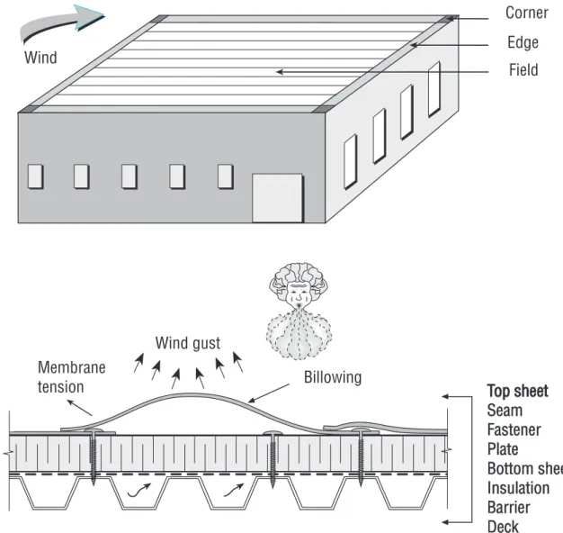
Mechanically attached roof membranes respond to wind loading differently than other roof coverings. Wind-induced suc-tion repeatedly lifts the membrane be-tween the attachments and causes elon-gation and billowing (see Figure 1). This can lead to fatigue of the membrane, fasteners, substrate and fastener/deck connection.
Roof system performance depends on component-to-component resistance to wind uplift. All resistance links must
Figure 3: The membrane tear underneath the fastener plate was caused by a lack of clamping force.
Figure 2: Resistance links of a mechanically attached roof system
Seams
There are two basic types of seams used for mechanically attached flexible mem-brane roofs. An asymmetrical seam is the most common arrangement for ther-moplastic membranes (see Figure 4). Although such a seam can be designed successfully, wind loading causes greater stress to this type than to its symmetrical counterpart.
A symmetrical seam substantially re-duces force eccentricity compared with asymmetrical designs because of a re-duction of the forces attempting to over-turn the fastener plate and rock the fas-tener shank as shown in Figure 5.
Fasteners
Fastener plates and batten bars maintain a clamping force on a membrane to
deter tearing and slippage from under the plate. Fastener plates with barbs pro-vide increased resistance to membrane slippage (see Figure 6). Some fastener plate designs provide resistance to “pop up,” which occurs when insulation com-presses or a fastener backs out and risks puncturing the membrane. If a plate is an anti-pop-up type, membrane punc-ture is unlikely, but plate compression still can occur, making a membrane sus-ceptible to tearing at fastening points.
Batten bars distribute loads by provid-ing a clampprovid-ing force to deter membrane tearing and slippage. They need to be suitably robust to withstand repeated dynamic loading from high-wind events without deforming.
The membrane attachment method significantly influences a mechanically attached roof’s wind-uplift performance
Membrane
Peeling force
Fastener and plate
Seam
Tensile force
Tearing force
Membrane
Tensile force
Tearing force
Fastener and
batten strip
Tensile force
Tearing force
with fastener thread designs playing a vital role in resistance. Anti-backout fasteners are recommended because of their thread design, which reduces the potential for backout.
The orientation of fastener rows with respect to deck flanges affects the con-nection of a deck to supporting beam/ joists. If membrane fastener rows are perpendicular to the flanges, the deck/ support attachment loads are reduced. Therefore, engineers recommend fas-tener rows perpendicular to the deck flanges (see Figure 7).
Insulation and cover boards
The control of heat movement through a roof system depends almost exclusively on the insulation, which also has an im-portant role in a roof assembly’s wind-uplift performance. Although many types of thermal insulating materials are avail-able, polyisocyanurate insulation is used for a majority of mechanically attached flexible membrane roofs.Thicker insulation requires a longer fastener shank. This can apply a greater rocking force; if this force is sufficient enough to crush the insulation, the rock-ing of the fastener results in a reduction of the plate’s clamping force. The fas-tener’s horizontal rocking movement is reduced when an air/vapor retarder is installed as part of the roof assembly be-cause it distributes the load. When no retarder is used, insulation thickness has minimal effect on the wind-uplift ratings of mechanically attached systems.
Cover boards provide several benefits, including:
• Protecting insulation from mechanical damage caused by traffic loads • Preventing fastener plates from causing
localized crushing of insulation during high winds
• Providing some protection for heat-sensitive insulation boards during torch applications
• Reducing the risk of problems from condensation within the roof assembly • Protecting the insulation from solvent
degradation
Figure 4: Asymmetrical seam for a thermoset membrane
42 August 2006 www.professionalroofing.net
• Providing a moisture buffer between the insulation and roof membrane
• Improving fire resistance
Vapor retarders
Vapor retarders limit airflow into a roof system, which reduces energy losses in the assembly. They can reduce membrane flutter and should be used wherever moderate winds are frequent.Vapor re-tarders commonly are constructed with sheet materials, such as polyethylene. (A two-ply built-up sheet or one-ply modi-fied bitumen sheet also can be used.)
quite a while, resulting in a large area of wet roof insulation.
Deck
Decks and deck attachments are essential features of mechanically attached flexi-ble membrane roof systems. Plywood, wood, plank, concrete or steel are used on roofs with flexible membranes. For roofs with high design uplift loads, a thicker deck and stronger fasteners or denser patterns should be specified to provide added resistance.
The deck attachment of the support-ing structure must resist design uplift loads adjusted for the safety factor. It is desirable to use short membrane fasten-ers that engage the top of a deck’s flange to reduce the fastener’s rocking movement.
However, when there are multiple lay-ers of insulation or tapered insulation or if a roof is being re-covered, limiting at-tachment to the top flange can be time-consuming and difficult compared with using fasteners long enough to engage the bottom flange. In this situation, it is better to increase fastener density.
They all work together
The successful design and construction of mechanically attached flexible mem-brane roofs is a factor in calculating wind forces and ensuring the links be-tween roof elements are capable of re-sisting them. For membrane roofs, this means selecting a material adequately tested using dynamic loadings simulat-ing in-service conditions.
Bas A. Baskaran is group leader of the Perfor-mance of Roofing Systems and Insulation subprogram at the Institute for Research in Construction, which is part of the National Research Council of Canada in Ottawa.
When sheet products are used, they are applied directly over the deck. The joints of polyethylene sheets are sealed with tape or sealant before insulation/cover boards are placed and mechanically fas-tened to the deck. This means the air retarder assembly (insulation boards, fas-teners and other components above the vapor retarder) must be designed to re-sist 100 percent of the design uplift load (adjusted for safety factor).
Although air retarders have many ben-efits, they can make it more difficult to detect leaks. So a small opening in a roof membrane can go unnoticed for
For a link to the SIGDERS Web site and a list of SIGDERS members, log on to www. professionalroofing.net.
Membrane fastener rows
Line of deck attachment
Figure 6: Typical membrane fastener plates
Figure 7: Influence area as a function of fastener row orientation—membrane fastener rows are perpendicular to the deck flanges