Automatic Vision-Guided Micromanipulation
for Versatile Deployment and Portable Setup
The MIT Faculty has made this article openly available. Please share
how this access benefits you. Your story matters.
Citation
Yang, Liangjing, Ishara Paranawithana, Kamal Youcef-Toumi, and
U-Xuan Tan. “Automatic Vision-Guided Micromanipulation for Versatile
Deployment and Portable Setup.” IEEE Transactions on Automation
Science and Engineering 15, no. 4 (October 2018): 1609–1620.
As Published
http://dx.doi.org/10.1109/TASE.2017.2754517
Publisher
Institute of Electrical and Electronics Engineers (IEEE)
Version
Author's final manuscript
Citable link
http://hdl.handle.net/1721.1/120060
Terms of Use
Creative Commons Attribution-Noncommercial-Share Alike
The final publication is available at http://dx.doi.org/ 10.1109/TASE.2017.2754517
"Automatic Vision-Guided Micromanipulation for Versatile Deployment and Portable Setup." IEEE T-ASE (2017).
Abstract— In this paper, an automatic vision-guided micromanipulation approach to facilitate versatile deployment and portable setup is proposed. This work is motivated by the importance of micromanipulation and the limitations in existing automation technology in micromanipulation. Despite significant advancements in micromanipulation techniques, there remain bottlenecks in integrating and adopting automation for this application. An underlying reason for the gaps is the difficulty in deploying and setting up such systems. To address this, we identified two important design requirements, namely portability and versatility of the micromanipulation platform. A self-contained vision-guided approach requiring no complicated preparation or setup is proposed. This is achieved through an uncalibrated self-initializing workflow algorithm also capable of assisted targeting. The feasibility of the solution is demonstrated on a low-cost portable microscope camera and compact actuated micro-stages. Results suggest subpixel accuracy in localizing the tool tip during initialization steps. The self-focus mechanism could recover intentional blurring of the tip by autonomously manipulating it 95.3 % closer to the focal plane. The average error in visual servo is less than a pixel with our depth compensation mechanism showing better maintaining of similarity score in tracking. Cell detection rate in a 1637-frame video stream is 97.7% with subpixels localization uncertainty. Our work addresses the gaps in existing automation technology in the application of robotic vision-guided micromanipulation and potentially contribute to the way cell manipulation is performed.
Note to Practitioners—This paper introduces an automatic method for micromanipulation using visual information from microscopy. We design an automatic workflow, which consists of 1) self-initialization, 2) vision-guided manipulation and 3) assisted targeting, and demonstrate versatile deployment of the micromanipulator on a portable microscope camera setup. Unlike existing systems, our proposed method does not require any tedious calibration or expensive setup making it mobile and low-cost. This overcomes the constraints of traditional practices that confine automated cell manipulation to a laboratory setting. By extending the application beyond the laboratory environment, automated micromanipulation technology can be made more ubiquitous and expands readily to facilitate field study.
Index Terms—Cell Manipulation, Robot Vision Systems
*Research supported by SUTD-MIT International Design Centre (IDC). Liangjing Yang is with the Mechanical Engineering Department, Massachusetts Institute of Technology (MIT), Cambridge, MA, USA (phone: +1-(617)258-6785; e-mail: [email protected]).
Ishara Paranawithana is with the Pillar of Engineering Product Development, Singapore University of Technology and Design (SUTD), Singapore (e-mail: [email protected]).
I. INTRODUCTION
UTOMATION in micromanipulation has an important role in the advancement of cell manipulation. It contributed immensely towards the ease of operation, speed, accuracy, and repeatability in cell manipulation. With more elegant manipulation mechanisms [1-4] and intuitive interfaces [5-8], micromanipulators are operated with greater ease. In addition, shorter operation time, higher precision, and better consistency can readily be achieved by robotic micromanipulators [9]. Such contributions enhance the execution of cell manipulation procedures in biomedical applications [10, 11] and are also paramount to the advancement of our understanding in cell biology [12-14].
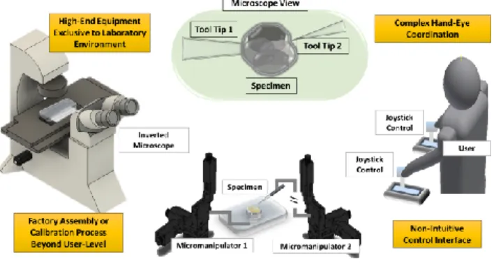
In addition to the importance of micromanipulation, this work is also motivated by the need for and the limitations of existing systems in cell manipulation applications. Fig. 1 is a graphical summary of the existing limitations of a typical micromanipulation process. The graphical illustration depicts a typical teleoperation of the micromanipulator by a user manually and the existing challenges to be discussed.
Current practices depend largely on manual operation which limits the speed of operation, and more importantly, the reproducibility of the study. Existing commercial mechanical micromanipulators [15-17] are mainly operated manually despite some having semi-automatic features for programed or stored positions. The teleoperation interface also requires hand-eye coordination and mental registration of the manipulator control with the visual information perceived by the user.
Although the state-of-the-art design in micromanipulator [1-7] has enabled enhanced performance in terms of speed and precision with relatively greater ease, the field of automation has not been fully leveraged for the applications of cell manipulation. Research efforts [18-26], including our previous work [27-29], to equip microscopic imaging and cell manipulation with visual robotic guidance have been proposed to address the needs for systematic, consistent, and efficient micromanipulation. However, there remain restrictions and challenges in incorporating automation for cell manipulation.
Kamal Youcef-Toumi is with the Mechanical Engineering Department, MIT, Cambridge, MA (e-mail: [email protected]).
U-Xuan Tan is with the Pillar of Engineering Product Development, SUTD, Singapore (e-mail: [email protected]).
Automatic Vision-Guided Micromanipulation
for Versatile Deployment and Portable Setup
Liangjing Yang, Member, IEEE, Ishara Paranawithana, Kamal Youcef-Toumi, Member, IEEE,
U-Xuan Tan, Member, IEEE
The final publication is available at http://dx.doi.org/ 10.1109/TASE.2017.2754517
"Automatic Vision-Guided Micromanipulation for Versatile Deployment and Portable Setup." IEEE T-ASE (2017).
An obvious reason for these restrictions is the difficulty in moving the system around and getting it ready for operation. A self-contained system that allows versatile deployment and portable setup is not available. Micromanipulation is often carried out using sophisticated setup exclusive to laboratory environment [16]. Restricting the study to a laboratory condition limits the accessibility of the technology. Without a self-contained solution that is portable and deployable beyond laboratory, automatic solutions are less readily adopted for micromanipulation applications.
To solve the above problems, we identified two important design requirements, namely versatility and portability. We argued that the source of the bottlenecks is the difficulty in preparing and moving such setups around for study. To tackle this underlying issue, a solution that incorporate automatic micromanipulation while facilitating versatile deployment and portable setup is required.
Fig. 1. Setup of a typical micromanipulation application illustrating the limitations and challenges in current practice
The contribution of this work is the development of an automatic vision-guided micromanipulation platform with versatile deployment and portable setup. This platform integrates previously developed self-initialization workflow algorithm and a unified track-servo framework that requires no calibration [28, 29]. Here, our design goal is to develop a self-contained solution requiring no factory setup or calibration procedures for automated manipulation of tool tip to specimen. Demonstrating the integration of our automated modules seamlessly for deployment in portable setup, which has not been addressed previously, is discussed in this paper. This contribution will make the automation technology more ubiquitous in the field of micromanipulation.
The scope of this paper will be organized thematically. In Section II, we survey related work to understand the needs in the current practice and the gaps in existing solutions. This review of the related work allows us to conceptualize and present an overview of our solution in Section III. The algorithms that realized the automatic vision-guided micromanipulation system will be discussed in Section IV. In Section V, specifications of a versatile deployment and portable setup is presented. Finally, results on the performance of our developed system are discussed in Section VI before concluding by re-iterating the significance of this study and a brief remark on potential future work in Section VII.
II. LITERATURE REVIEW
The objective of this section is to survey the existing work relevant to the development of an automatic vision-guided micromanipulation. We start by defining the scope of our development in terms of the form of manipulation and the focus of our problem. We will review work related to vision-guided micromanipulation to understand the limitations in existing development. Limitation in our previous work which leads to this current development will also be discussed in this section.
The scope of our development focuses on mechanical manipulation because of the relatively more generalizable design concept compared to the other manipulation mechanism. However, there exist several forms of micromanipulation system in the literature. Apart from mechanical micromanipulators [30-32], some other representative examples include magnetic microrobots [7, 33, 34], optical tweezers [35-37], and microfluidic chips [38, 39]. Magnetic microrobots and optical tweezers may require technologies which are not easily deployable beyond the laboratory environment. While microfluidic chips have the potential to achieve high throughput processes, they may require application-specific designs. We will also limit our work to designing a solution for manipulating the position of tool tips that is usually a micro-pipette or -needle. Nevertheless, it is interesting to note that there are many other form of microgripper. In fact, contact and gripping dynamics are subjects of great interest in micromanipulation [40-44] due to the unique phenomenon of dominance adhesion forces [45].
There has been an extensive research effort in vision-guided micromanipulation over the past decade. Pioneering work by Sun and Nelson [22, 46] used direct visual servo method for micromanipulation. This image-based visual servo uses image feature parameters to formulate the mapping of the error in the sensor space to that of the task space via an image Jacobian [47]. A later work by Wang et al. [48] demonstrated an automatic solution for microinjection of preloaded array of zebrafish embryo each with dimension of 0.6-1.2 mm.
Despite the promising development, most of the micromanipulation systems are still manually teleoperated as suggested in a comprehensive survey on micromanipulation strategies by Savia et al. [45]. It appears that the source of the gap stems from the challenges to incorporate or setup a system with full automation capability.
One such challenge is the registration between the manipulator and the imaging system. This form of registration aims to establish a relationship that maps one coordinate system to another. Registration of the manipulator joint coordinate system with the microscope image coordinate system is usually done through careful prior calibration of the systems [20, 21, 23, 49, 50]. This is common for robotic vision applications where mapping of coordinates between the sensor or image space to the actuator task space is important [51, 52].
For microinjection application, the described challenge is particularly critical as the insertion path must align precisely with the specimen in the imaging plane as pointed out by many researches [22, 46, 53]. This usually requires careful calibration or precise mounting of the manipulator relative to the
The final publication is available at http://dx.doi.org/ 10.1109/TASE.2017.2754517
"Automatic Vision-Guided Micromanipulation for Versatile Deployment and Portable Setup." IEEE T-ASE (2017).
microscope to ensure that the x-y positioning plane of the manipulator is accurately in parallel with the imaging plane. To complicate matters, the absence of depth perception and limited depth-of-view make manual focusing and maintaining planar motion extremely difficult [20]. Therefore, most work requires registration to be done in order to execute planar motion in the 3D task space during automated micromanipulation.
System registration is challenging in micromanipulation because the microscope is mounted with a monocular camera. Calibration of the microscope camera through multiple views is not feasible making camera internal parameters and optical center location challenging to estimate. Mapping between the tool tip and the camera coordinate systems is typically obtained using 3D calibration patterns [20, 21, 49, 50] or the known kinematics of the manipulator [53-55]. The mapping is only consistent when the operation is done without changing the positional and optical properties of the setup. This restrict the deployment of system to the laboratory environment.
To work around the such restriction, Sun and Nelson [22, 46] proposed a direct visual servo which uses the image feature parameters to represent the error signals. This is done using an image Jacobian which maps the task space to sensor space coordinates. The method also performs autofocusing using a template similarity-score based method to position the needle in focus. Although it is not stated if the autofocus mechanism is integrated into the control scheme for maintaining the needle in the focal plane, it is mentioned that the injection pipette is lowered after switching among specimen before returning it to focus. This means that the tip must always be initialized from a given position hence suggesting that the autofocusing is not concurrent with the injection trajectories. Although initialization may be automated, it has to be done repetitively. This approach is valid with a laboratory microscope and micromanipulator with precise factory assembly between microscope and micromanipulator systems. As needle in focal plane is not done concurrently during manipulation, it may not be suitable for ad hoc deployment of micromanipulator where the manipulation and imaging plane are not necessarily parallel.
To provide a self-contained solution and avoid the need for calibration while maintaining focus on-the-fly, an uncalibrated method for concurrent compensation of planar misalignment during manipulation is developed [28]. This method unified the visual tracking and servo processes by using the template coordinates and similarity score of a region of interest (ROI) to feedback manipulation errors in 3D space. The feasibility and ease of integration was demonstrated with an inverted microscope. Despite being equipped with an intuitive interface through an interactive display, users still need to locate and focus the tip manually.
To further enhance the automation workflow, a self-initializing method is proposed [29]. This method, termed Detect-Focus-Track-Servo (DFTS), uses motion cue feature detection to localize an initial position of the needle tip within an ROI. A self-focusing process is subsequently performed to manipulate the needle in alignment with the focal plane. However, our previous work on vision-based control did not address the issue of automatic specimen localization.
Automatic localization of desired target on the specimen is an important provision towards the prospective development of an autonomous cell manipulation system. In addition, the self-contained workflow has not been deployed on a portable setup.
Object localization and tracking are relevant for vision-guided micromanipulation. They translate visual signal into meaningful spatial information for vision-based control. Objects to be localized include tool tips and specimens under the microscope. A recent work by Liu et al. introduced a fully automated solution for locating the tool tip [56]. In our previous work [27], we demonstrated tracking on both micropipette and blastomere in embryo biopsy during Preimplantation Genetic Diagnosis (PGD) [10, 11] . It is interesting to note a work by Wang et al [57] that visually servoed a micropositioning system at 30 Hz for automatic locomotive feature extraction. These studies supported the feasibility of visual servo via tracking.
III. OVERVIEW OF THE DESIGN CONCEPT
A. Conceptualization and Specification
Limitations discussed in the survey of existing works suggested that there is a need to make automatic micromanipulation technology more ubiquitous and readily available. As identified, the source of the bottlenecks is the difficulty in moving such systems around and preparing it for operation. To provide a holistic solution for these identified needs, versatility of deployment and portability of setup are identified as the two important design requirements. This means that the setting up process should not involve any exclusive factory assembly or tedious calibration procedures while facilitating a seamless automated workflow.
From the specified requirements, the design goal is to develop a solution that enables mobile setting up of the micromanipulation platform beyond laboratory environment. Therefore, our proposed approach incorporates an automatic vision-guided micromanipulation solution that is portable and versatilely deployable. This is done through a self-initializing algorithm and an uncalibrated vision-based approach featured in our previous study [28, 29]. In this work, we further expand the approach to include assisted targeting. The solution is designed to be self-contained making it mobile and easy to deploy outside laboratory environment.
The concept of our solution comprises an operation workflow and the appropriate system components to facilitate automatic vision-guided manipulation. These components, including the modular DFTS and cell detection algorithm are introduced in the subsequent two subsections.
B. Operation Workflow
The workflow algorithm consists of three sequential procedures including 1) self-initialization, 2) vision-guided manipulation, and 3) assisted targeting. These procedures, illustrated in Fig. 2, reflect the operational specifications of our design concept in developing an automatic vision-guided micromanipulation platform. This approach is adaptable and scalable, which facilitates portable setup & versatile deployment. This section introduces the procedural concepts
The final publication is available at http://dx.doi.org/ 10.1109/TASE.2017.2754517
"Automatic Vision-Guided Micromanipulation for Versatile Deployment and Portable Setup." IEEE T-ASE (2017).
leaving details of the algorithms to be discussed in Section IV.
Fig. 2. Workflow of Automatic Vision-Guided Micromanipulation; Self-Initialization and Vision-Guidance are based on DFTS Algorithm [29] During self-initialization, the system detects and localizes the tip of the tool. This is done by establishing an ROI which indicates the location and a rectangular boundary of the tip. The needle tip in the ROI is brought into focus using a self-focus manipulation technique proposed in our previous work [29]. This initialized ROI serves as the template to be matched with in subsequent frames during microscope imaging.
Once the location of the tip is available through template tracking, the next step is to control the manipulation path based on visual feedback of the tip’s location. This step integrates an algorithm proposed in our previous uncalibrated approach for vision-guided micromanipulator [28]. To facilitate an uncalibrated operation, an image-based visual servo approach is used. Error signal is represented in the image feature parameters. The unique feature of this approach is that it also controls the distance of the tool tip from the focal plane while executing trajectory in 3D space. This is done by taking the similarity score of the template matching results as a feedback signal for maintaining motion within the focal plane.
Finally, assisted targeting of cell specimen is carried out to complete the automated workflow. Hough transform is used to identify and localize a particular cell intended to be reached by the tip. By identifying and localizing the cell, subsequent path planning or assisted cell targeting can be implemented accordingly. The feasibility of this concept is demonstrated for the application of embryo extraction [27].
C. System Component
The system architecture comprises three modular components, namely the micromanipulation mechanism, microscope imaging system, and an interactive control interface. These components represent an overview concept of the essential modules for the implementation shown in Fig. 3. This section outlines the modular components leaving the precise technical specifications to be discussed in Section V.
The micromanipulation mechanism consists of three actuated micro-stages configured to form a Cartesian robot. This configuration facilitates easy assembly and portability. With a simple and generalizable design, the mechanism can be readily deployed with the previously introduced workflow to work alongside any existing microscope system, including a portable one, with minimal preparation work involved.
Fig. 3. Architecture of the Automatic Vision-Guided Micromanipulation In our proposed solution, the microscope imaging system is a portable digital microscope camera. This allows mobile on-site examination of specimens outside the laboratory. Digital image acquisition can also be made more ubiquitous by using a camera with USB compliant interface.
An intuitive user interface is designed to translate the user’s intention to manipulator motion. This includes an interactive display of the microscope view, which allows the user to select entities or specify path directly on the displayed view itself. Unlike conventional telecontrol interface, this interactive display approach makes manipulation intuitive as the user does not have to mentally coordinates the respective axis-of-control with the eventual motion in the task space. In addition, there is no issue with depth perception as the depth compensation mechanism in the workflow algorithm takes care of planar misalignment in the tip motion. Details of this workflow mechanism is discussed in the next section.
IV. AUTOMATIC VISION-GUIDED MICROMANIPULATION At the heart of our proposed solution lies the concept of an automatic vision-guided micromanipulation platform. It is built upon three important cornerstones to achieve a self-contained solution that is portable and easy to deploy. The following subsections will discuss these three components, namely the 1) self-initializing workflow, 2) vision-guided manipulation, and 3) assisted targeting.
A. Self-Initializing Workflow
Self-initialization enables the tool tip to be automatically detected, localized, and focused. This eliminates the need for tedious locating and focusing of tool tip manually. A feature-based approach and a regional-histogram-variance-maximizing scheme are used to detect-localize and self-focus the tip, respectively.
1) Detect-Localize
The detect-localize step uses a motion-cue corner detection approach to detect and localize the tool tip. The objective is to localize the tip for subsequent specification of an ROI. This is done by actively moving the tip to create a change in its position. Image subtraction is performed on temporally adjacent frames. The resulting difference image is subsequently processed for corner detection. The tip is localized by the image coordinates of the strongest corner. There is no significant
The final publication is available at http://dx.doi.org/ 10.1109/TASE.2017.2754517
"Automatic Vision-Guided Micromanipulation for Versatile Deployment and Portable Setup." IEEE T-ASE (2017).
difference in the choice of corner detector. Harris corner detector [58] is used in this work for its popularity and moderate computation requirement relative to existing algorithms in the literature. In this algorithm, the strength of a corner is represented using the feature response,
21 2 1 2
C
k
(1)where λ1 and λ2 are eigenvalues for the covariance of the sum-of-squared-difference (SSD)
2 , ( , ) ( , ) Q P SSD p q w x y
I p q I px qy (2) of patch I centered on (p,q) and itself when shifted by (x,y). The parameter k is a tunable value controlling the sensitivity of the response function. Harris and Stephens[58] further used the structure tensor S of the SSD to define an inspired feature response function to avoid the need for tedious eigenvalues computation. Hence, we can locate the tip in the difference image based on the strongest response of the inspired expression written as
2
max det( ) trace
tip
C S k S . (3)
It is essential that the corner detection is done in the domain of the difference image. As discussed in the workflow, the detect-localize step is done before focusing. Because we are dealing with unfocused tool tip, it is not feasible to use conventional passive corner detectors that do not work well for blurred images. Unlike pure feature-based detection which rely mainly on sharp intensity changes in image space indiscriminately, we use active motion cue to amplifiy the specific object of interest. This way corner detection is done selectively on the enhanced tool tip as the static background is suppressed by image subtraction.
In addition, doing feature extraction in the domain of the difference image allows detection of the tool tip without the need for high level feature recognition and computationally expensive segmentation. The removal of irrelevant static background features through a simple image subtraction operation offers a convenient yet robust means to enhance the tool tip as the most prominent corner. Based on our observation, salt and pepper noise, which might affect the detection outcome, can be easily removed using a constant intensity threshold value.
2) Self-Focusing
A regional histogram-based method is used to focus a specific ROI once detection of the tool tip is done using the motion-cue detection. This step is termed self-focusing to distinguish it from the usual autofocus mechanism, which adjusts the lens. The rationale of self-focusing is not to focus the scene by moving the lens. It is about bringing the manipulated object, which is the tool tip in this case, to focus. This does not change the entire scene. Current practices involve user moving the tool tip while the focused specimen remaining stationary. Our proposed self-focusing method automatically brings the tool tip into focus.
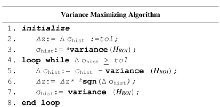
A histogram-based variance maximizing approach is used to
realize an online self-focusing mechanism. This is done in a gradient ascending fashion to maximize variance σhist for histogram HROI associated with the ROI by updating the tool tip
position as described in Table I.
TABLE I. PSEUDO-CODE FOR SELF-FOCUSING
Variance Maximizing Algorithm
1. initialize
2. Δz:= Δσhist :=tol;
3. σhist:= avariance(HROI);
4. loop while Δσhist > tol
5. Δσhist:= σhist -variance (HROI);
6. Δz:= Δz* bsgn(Δσhist);
7. σhist:= variance (HROI);
8. end loop
a. variance() is a function that returns the statistical variance; b. sgn() extracts the sign
Like many other histogram-based methods applied in microscopy [59], this method does not require any active signal source or additional sensors making it easy to deploy and suitable for portable platforms. In addition, the approach can be readily generalized to applications that uses different focus functions [60] to self-focus tool tip. In our implementation, we assume that focus occur at maximum variance σhist of the histogram HROI [61]. As in the case of many histogram-based
approaches, this method is unsuitable for moving scene but works satisfactorily for an initial self-focusing step. To realize vision-guided manipulation, a similarity score-based approach, is implemented to maintain the focus of the tip during manipulation as will be discussed in the next section.
B. Vision-Guided Manipulation
To achieve vision-guided manipulation without prior calibration, the system need to control the tool tip with feedback signal in the imaging domain. This includes tracking of the ROI representing the tool tip. In addition, the similarity score-based depth compensation is required to maintain the 3-DOF motion of the tool tip within the focal plane which is not assumed to be in alignment with the x-y plane of the manipulator. As our development goal is to deploy portable setup without calibration, the image-robot coordinate transformation is not assumed to be known.
1) Tracking of Region-of-Interest
The ROI specified during the self-initializing phase is registered as a template for tracking during vision guided manipulation. Based on a score w computed from the normalized cross-correlation of the template g with a patch f in subsequent imaging frames, a matching patch is then selected as the updated position.
The cross-correlation wcc(u,v) at image coordinates (u, v) of
a template patch g(p,q) and the image f(p,q) is expressed as
0 0 , , , Q P cc p q w u v g p q f p u q v
The final publication is available at http://dx.doi.org/ 10.1109/TASE.2017.2754517
"Automatic Vision-Guided Micromanipulation for Versatile Deployment and Portable Setup." IEEE T-ASE (2017).
for a P x Q patch and U x V image. To further account for the sensitivity of cross-correlation index due to intensity variation, Equation (4) is re-expressed as the normalized cross-correlation coefficient w
2 2 0.5 0 0 0 0 0 0 , Q Q Q P P P p q p q p q w u v G F G F
whereG
g p q
,
g
and F f p u q v
,
f u v
, . Notationg and f represent the mean intensity value in the template and the overlapping region, respectively.Apart from tracking of the relevant ROI, the score also functions as a source of depth compensation in our vision-guided manipulation. With the newly introduced w, the sensor coordinates can now be written as (u, v, w) where u and v are spatial coordinates of the pixel while w is an intensity-derived coordinate represented by the similarity score between the template and the overlapping region. The next section will describe how the similarity score is used to compensate for motion that went out of focal plane.
2) Similarity-Score-Based Depth Compensation
To solve the problem of tool tip moving out of the focal plane during the manipulation, our vision-guided control uses the similarity score to compensate the depth of the tip so as to keep it in focus. This is done in an online manner where the z-axis of the manipulator compensates for the deviation from focal plane concurrently with the x-y motion that manipulates the tip to its target. Our method avoids tedious calibration by coordinating the joints to maintain planar manipulation.
The goal is to maximize the similarity-score while actuating the manipulator joints assuming that the similarity between the template and a detected patch is at maximum when in focus. Similar assumption has been used in existing systems [22, 46] for focusing tool tip done as a separated independent step from visual servo. In our method, the z-position of the manipulator is adjusted online in a gradient ascending fashion during manipulation to maximize the score. As shown in the pseudo code of Table II, the tool tip will be adjusted in the z-direction by Δz such that the change in score Δw converges to a preset tolerance tol.
TABLE II. PSEUDO-CODE FOR ADAPTIVE COMPENSATION
Gradient Ascending Updating Algorithm
1. initialize 2. Δz:= Δw:=tol;
3. w:= acompute_score(g,f);
4. loop while Δw > tol
5. Δw:= w- compute_score(g,f);
6. Δz:= Δz* bsgn(Δw);
7. w:=compute_score(g,f);
8. end loop
a. compute _score() denotes a function that implement Equation 5 b. sgn() extracts the sign
The presented algorithm adopts a simple but practical approach for online depth compensation in 2D microscopy. The autofocusing problem with anterior-posterior ambiguity is spontaneously resolved by the gradient-ascending update. Furthermore, this approach can be implemented on uncalibrated systems as it circumvents the need for depth recovery issues, which are non-trivial in the case of a fixed 2D microscope camera [54, 62]. For this reason, the approach is generalizable for any general micromanipulation system. In addition, the adjustment mechanism is stable due to the diminishing rate of change in the similarity score when the tip moves away from the focal plane as demonstrated in previous work [28].
3) Visual Servoing with Depth Control
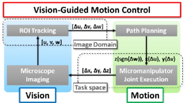
Our system executes 3D trajectories using information associated with the image coordinates and intensity values of 2D microscopy. This vision-guided servoing is realized through the combination of the methods discussed in the previous two subsections. The key concept is to formulate a meaningful error signal in the image domain. By obtaining the image coordinates and similarity score of the ROI, the error signal can be expressed as [Δu, Δv, Δw]. The working mechanism of this vision-guided motion control scheme is illustrated by the flow diagram in Fig. 4.
The feedback mechanism allows easy decoupling of the Cartesian axis-of-control. Error signal from the image coordinates [Δu, Δv] of the tracked ROI is used to update joint input for x- and y-axis of the manipulator based on specific function x(Δu) and y(Δv), respectively. For generality, we update the x- and y-joint inputs using a simple proportional gain. Joint input for z-axis is updated using the error signal from the similarity score, Δw of the tracked ROI. The input z(sgn(Δw)) is computed per the gradient ascending algorithm as describe in Section IV. B. 2).
Fig. 4. Architecture of the Automatic Vision-Guided Micromanipulation Our proposed visual servo with depth compensation of the tip not only avoid the problems of complicated calibration and tedious precision mount, it also facilitates intuitive manipulation of the tool tip without the user having to worry about depth perception as this is automatically dealt with by the depth compensation feature of our method.
C. Assisted-Targeting
To further streamline the automation workflow of the vision-guided micromanipulation process, an assisted targeting
The final publication is available at http://dx.doi.org/ 10.1109/TASE.2017.2754517
"Automatic Vision-Guided Micromanipulation for Versatile Deployment and Portable Setup." IEEE T-ASE (2017).
mechanism is incorporated. This locates the cell and bring the needle tip towards it. Essentially, this procedure consists of detecting and localizing the cell specimen as the target such that a path can be planned for the manipulation of the tool tip.
In this study, a cell specimen is detected and localized using the circle Hough transformation [63]. Localization of circular embryonic specimen with this approach is discussed in our previous study [27]. In essence, this approach maps the Cartesian coordinates of candidate points extracted from Canny Edge detection [64] to their respective loci in the Hough space. The parameters of the circle, including its location, is subsequently identified based on overlapping counts of the loci.
The Hough space parameters are the radius of a circle and the coordinates of its center. Hence, for a cell specimen that is in the image, we can write the square of its nominal radius
2
2
2cell cell cell
R ux v y where (u, v) and (xcell, ycell) are the image coordinates of
candidate points and the image coordinates of the cell center, respectively. By plotting all the possible values of (xcell, ycell,
Rcell) associated with a particular candidate point (u, v), a
conical surface locus can be formed. The Hough space is then discretized with voxels containing the number of counts they coincides with the loci. The voxel with the highest count will have its coordinates (xcell, ycell, Rcell) corresponding to the
parameters of the circular cell. While the cell that is closest to the tool is selected in our previous study for embryo biopsy, current study will use a single-cell specimen for demonstration.
V. VERSATILE DEPLOYMENT AND PORTABLE SETUP In this section, we demonstrate the feasibility of the proposed solution through a low-cost portable setup consisting of the essential components described in the system architecture under Section III (c). The physical setup of the portable micromanipulation system is shown in Fig. 5. It consists of a workflow algorithm that allows versatile deployment and small footprint system components for portable setup.
The proposed solution is designed for versatile deployment and portable setup. This is realized through the uncalibrated self-initializing capability of the system. The uncalibrated nature of the workflow algorithm means that there is no need for precise factory assembly or careful prior calibration of the microscope and the micromanipulator. In addition, the self-initializing capability automatically localize and position the tool tip to be ready for tracking and visual servoing. This avoids the need for tedious manual locating or focusing of the tool tip.
We implemented motion control through an actuated 3-axis Cartesian manipulator. This configuration can be readily deployed anywhere without any constraint or requirement in the relative position of the micromanipulator and the microscope. Each axis of control (8MT173; Standa Ltd., Lithuania) has a resolution of 1.25 µm per step. A finer resolution of 5 nm can be further achieved through microstepping with the multiaxis controller (8SMC4; Standa Ltd., Lithuania). This modular controller interfaces with a host computer through USB. The workspace of manipulation is 20 x 20 x 20 mm3.
Fig. 5. Comparison of setup a) Portable microscope b) Inverted microscope system in laboratory
Microscope imaging is carried out using a USB digital camera (AM7013MZT Dino-Lite, AnMo Corp., Taiwan). This is a portable digital USB microscope camera with a 5-Megapixel CMOS image sensor. The magnification ranges from 20x to 50x continuously and a separate option for 200x. External illumination is not required as the portable microscope has built-in LED light source with adjustable polarizer.
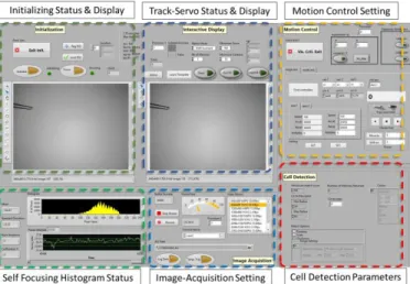
The user interface is an interactive display with virtual panels for specifying the operation setting depending on the user’s requirements. Fig. 6 shows the user interface. The controls and setting on the virtual panels are designed primarily for adjustment of settings in image analysis and motion control. Tool can be intuitively manipulated by the user using mouse cursor to specify directly on the microscope view display manually or together with the assisted targeting feature. The developed system can be readily set up with a general-purpose computer as the time-critical motion control loop is executed in the dedicated but compact 8SMC4 motion controller. In our setup, a 64-bit Windows 7 platform is used to host the user interface. The user interface and control applications are developed in LabVIEW Development Suite (National Instruments Inc., USA). Different resources of the multi-core processor (Intel® Core™ i5 2.5GHz) is assigned to process image acquisition, image processing, and control modules in a modular design.
The final publication is available at http://dx.doi.org/ 10.1109/TASE.2017.2754517
"Automatic Vision-Guided Micromanipulation for Versatile Deployment and Portable Setup." IEEE T-ASE (2017).
VI. RESULTS AND DISCUSSIONS
In this section, we discuss the experimental results of our proposed solution using the developed versatile and portable platform. The discussion covers quantitative evaluation of the various components and a demonstration of the operational feasibility in automated manipulation using our system. The former includes evaluation of the 1) detection of tool tip, 2) self-focus capability, 3) track-servo mechanism, and 4) assisted targeting of detected cell.
A. Performance Evaluation 1) Detection of Tip
Performance of the detection algorithm can be evaluated by comparing the accuracy of tip localization along a known path. Fig. 7 is a composite image overlaid with the various tip position illustrating its motion. The perpendicular distance from the tracked position to the desired path is the geometric error.
Fig. 7. Composite image showing motion of the tip and its tracked positions (pixel represents a 12.5µm by 12.5µm square in world space) The mean error of the 133 tracked frames is 0.421 pixels with a standard deviation of 0.384 pixels. The error distribution over the 133 frames is shown in Fig. 8. We also observed errors decreasing as the motion reaches constant velocity. In practice, only the final location is relevant during the initialization phase. Hence, these results are conservative estimations of the uncertainty.
Fig. 8. Error distribution over the 133 tracked frames
2) Focus of ROI
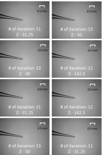
The tool tip is brought to focus from an intentionally blurred position to demonstrate the self-focusing mechanism. First, we manually bring the tip to focus and set the Z position as the origin (i.e. Z=0) as shown in Fig. 9 (a). Subsequently, intentional blurring of the tip is carried out by moving the tip away from the focal plane by 1000 steps (i.e. moving manipulator such that Z= -1000 steps) as shown in Fig. 9 (b).
This means that the tip is approximately 1250 µm away from the focal plane as each of the actuation step is 1.25 µm. Finally, the error in self-focusing is recorded as the difference in the Z position between the self-focused tip and the ideal focus. The results are presented in Fig. 10. Self-focusing is carried out at a speed of 62.5 µm/s (50 steps/s) in the Z axis-of-control. The number of iterations and final z position of each trial is indicated in the respective image.
The mean absolute error of self-focusing in 8 trials is 58.59 µm (= 46.875 steps) with values ranging from 30 µm to 142.5 µm (= 24 steps to 114 steps). This is about 95.3% closer to the focal plane. An average of 12 iterations were required to reach convergence in the 8 trials. This results is comparable to the study carried out on a commercial inverted microscope system (Leica DMi8; Leica Microsystems GmbH, Germany) previously [29]. Based on visual inspection, all 8 trials achieve focus with no observable difference in sharpness.
Fig. 9. (a) Ideal focus (b) Intentional blur (1250 µm away from focal plane)
The final publication is available at http://dx.doi.org/ 10.1109/TASE.2017.2754517
"Automatic Vision-Guided Micromanipulation for Versatile Deployment and Portable Setup." IEEE T-ASE (2017). 3) Track-Servo of Tool Tip
We evaluate the track-servo mechanism by executing known paths using the system. Fig. 11 shows the path taken by the tool tip. Two trials, Trial I and Trial II, were carried out where each trial executes four straight line path segments to form a square path of 1490 frames and 1420 frames, as illustrated in Fig. 11 (a) and (b), respectively. The solid lines are desired path while the color-coded data points are the actual path taken by the tool tip recording in image coordinates. Trial II was carried out with the motion of z-axis suspend to observe the outcome of visual servo without the score based depth compensation.
Fig. 11. Path of vision-guided manipulation (a) Trial I: executed using proposed mechanism (b) Trial II: Score-based depth compensation disabled
(Each pixel represents a 12.5µm by 12.5µm square)
Similar to the evaluation of the detection mechanism for localization, the perpendicular distance, in pixel, from the tracked position to the desired path is the geometric error of the location. The root-mean-square (RMS) error of the straight-line executions (speed ≈ 125 µm/s) are (0.95, 0.59, 0.72, 0.81) and (0.58, 0.77, 0.76, 0.85) for Trial I and II, respectively. The difference between the RMS errors with and without depth compensation is less than 0.5 pixel and they consistently achieved accuracy in the order of subpixel. Each pixel represents a 12.5µm by 12.5µm square in world space.
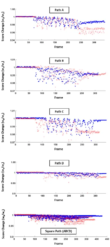
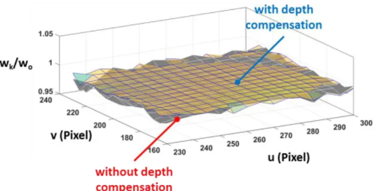
To demonstrate the effect of the score-based depth compensation, the similarity score profiles of Trial I and II are compared in Fig. 12. Because initialization may start with ROI of different scores, the computed scores are normalized by their initial values and plotted against their frame number. The blue and red dots in Fig. 12 represent the normalized scores of Trial I and Trial II, respectively. Surface plots based on C1 continuity interpolation of the data points from the square paths are generated for intuitive visualization of the comparison over the workspace as shown in Fig 13.
To further visualize the effect of the depth compensation mechanism on the improvement in tracking score, we generate the surface plot of the relative improvement in score and superimposed it on the executed square path in the workspace as shown in Fig. 14. It can be observed that visual servo with depth compensation generally maintained a score higher than that without depth control.
From the observation, we can infer that the similarity score based depth compensation maintains the tool tip closest to the
focal plane. With the implementation of the depth compensation, relative fall in score reduced to 0.61%. Without any depth compensation, the nominal drop in similarity score would have been 1.02%. This suggests that the method effectively control the depth without the need for tedious microscope-micromanipulator calibration.
Fig. 12. Similarity-score comparison between execution using our proposed mechanism (Trial I) and that with score-based depth compensation disabled (Trial II); blue dots and red dots represent scores of Trial I and II, respectively
The final publication is available at http://dx.doi.org/ 10.1109/TASE.2017.2754517
"Automatic Vision-Guided Micromanipulation for Versatile Deployment and Portable Setup." IEEE T-ASE (2017).
Fig. 13. Comparing with and without depth control over workspace
Fig. 14. Visualization of score improvement over the workspace
4) Assisted-Targeting of Detected Cell
To assess the uncertainty in cell detection, the process was carried out on a video stream while the cell is stationary. In this study, prawn eggs ranging from 400 µm to 600 µm in diameter, were used as the targeted specimen. The estimated location of its center (xcell, ycell) and radius Rcell are recorded. The standard deviations of xcell, ycell and Rcell are tabulated as δx, δy, and δr, respectively, in Table III. This indicates the uncertainty of the estimation. In this trial, it is observed that the detection rate is about 97.7% (1599 of 1637 tracked frames). The processing is done at 30 frames/s.
TABLE III. LOCALIZATION UNCERTAINTY AND DETECTION RATE
Uncertainty Detect Rate
(N=1637)
δx (pixel) δy (pixel) δr (pixel)
0.84 0.35 2.43 97.7%
**Each pixel represents a 12.5µm by 12.5µm square
B. Feasibility Demonstration
The proposed workflow algorithm and portable setup is demonstrated in the attached Media. In the video, an originally blurred tip is brought to focus by the motion-cue detection and ROI-specific self-focusing. At the same time, the cell is detected as the target. Subsequently, the manipulator executes the required path to bring the needle tip towards the target using the track-servo framework. The vision-guided manipulation is carried out at a speed of 125 µm/s. This can be readily increased to be comparable to manual manipulators and automated robotics systems for cell manipulation tasks [14, 26].
VII. CONCLUSION AND FUTURE WORK
An automatic vision-guided approach is proposed to facilitate versatile deployment and portable setup. Our approach enables mobile and low-cost design as it does not require any tedious calibration or specialized equipment. We demonstrated the feasibility of the development on a portable USB microscope system based on quantitative data and evaluation. The imaging system can be versatilely deployed with an arbitrary fixation because the self-initialization and unified track-servo framework can automatically localize and focus the tool tip subsequently executing 3D trajectory to manipulate the tool to an automatically detected target. Our developed platform overcomes the limitations of traditional practices confined in a laboratory environment. By extending the applications beyond the laboratory environment, micromanipulation technology can be made more ubiquitous and available for onsite cell study hence positively impacting the way cell study is being performed.
The experiment used prawn eggs to mimic prospective specimen for feasibility test. More application-specific and realistic experiments will be carried out in future work. One potential application is in PGD typically working with embryo of size 100 µm - 200 µm [65].
Future work will involve improving the level of autonomy in the vision-guided micromanipulation including more robust self-focusing and localization of the tool tip, and a deeper investigation of the target assisting method. Current work uses gradient ascending method to maximize the variance of the histogram for self-focusing. Like any other iterative method, the result of the focus function depends on the initial z position of the tool tip. Algorithms that are independent of initial conditions and circumvent local minimum should be considered. Deformation during tool-specimen interaction is another interesting area which we are investigating to ensure robust localization and uninterrupted tracking of the tool tip [66]. We have demonstrated assisted targeting with prawn cells, which are elliptical. However, cells with different shapes might not be detectable using our current algorithm as it is optimized for circular shape. Detecting different shapes of cells will be in our scope of interest for future work as well.
VIII. REFERENCES
[1] Y. Li and Q. Xu, "A novel design and analysis of a 2-DOF compliant parallel micromanipulator for nanomanipulation," IEEE transactions on
automation science and engineering, vol. 3, pp. 247-254, 2006.
[2] Y. Tian, B. Shirinzadeh, D. Zhang, X. Liu, and D. Chetwynd, "Design and forward kinematics of the compliant micro-manipulator with lever mechanisms," Precision Engineering, vol. 33, pp. 466-475, 2009. [3] Y. Li and Q. Xu, "Design and analysis of a totally decoupled
flexure-based XY parallel micromanipulator," IEEE Transactions on Robotics, vol. 25, pp. 645-657, 2009.
[4] U. X. Tan, W. T. Latt, C. Y. Shee, and W. T. Ang, "A Low-Cost Flexure-Based Handheld Mechanism for Micromanipulation," IEEE/ASME
Transactions on Mechatronics, vol. 16, pp. 773-778, 2011.
[5] M. Guthold, M. R. Falvo, W. G. Matthews, S. Paulson, S. Washburn, D. A. Erie, et al., "Controlled manipulation of molecular samples with the nanomanipulator," IEEE/ASME transactions on mechatronics, vol. 5, pp. 189-198, 2000.
[6] S.-G. Kim and M. Sitti, "Task-based and stable telenanomanipulation in a nanoscale virtual environment," IEEE Transactions on automation
The final publication is available at http://dx.doi.org/ 10.1109/TASE.2017.2754517
"Automatic Vision-Guided Micromanipulation for Versatile Deployment and Portable Setup." IEEE T-ASE (2017).
[7] G. Lucarini, S. Palagi, A. Levi, B. Mazzolai, P. Dario, A. Menciassi, et
al., "Navigation of Magnetic Microrobots With Different User Interaction
Levels," IEEE Transactions on Automation Science and Engineering, vol. 11, pp. 818-827, 2014.
[8] H. Terada, K. Makino, H. Nishizaki, E. Yanase, T. Suzuki, and T. Tanzawa, "Positioning Control of a Micro Manipulation Robot Based on Voice Command Recognition for the Microscopic Cell Operation," in
Advances in Mechanism Design II, ed: Springer, 2017, pp. 73-79.
[9] J. P. Desai, A. Pillarisetti, and A. D. Brooks, "Engineering approaches to biomanipulation," Annu Rev Biomed Eng, vol. 9, pp. 35-53, 2007. [10] K. Sermon, A. Van Steirteghem, and I. Liebaers, "Preimplantation genetic
diagnosis," The Lancet, vol. 363, pp. 1633-1641, 2004.
[11] V. C. Y. Lee, J. F. Chow, W. S. B. Yeung, and P. C. Ho, "Preimplantation genetic diagnosis for monogenic diseases," Best Practice & Research
Clinical Obstetrics & Gynaecology, 2017.
[12] E. G. Diacumakos, "Methods for micromanipulation of human somatic cells in culture," Methods in cell biology, vol. 7, pp. 287-311, 1974. [13] F. Sherman, "Use of micromanipulators in yeast studies," Methods in cell
biology, vol. 11, pp. 189-199, 1975.
[14] Z. Lu, C. Moraes, G. Ye, C. A. Simmons, and Y. Sun, "Single cell deposition and patterning with a robotic system," PLoS One, vol. 5, p. e13542, 2010.
[15] E. Pearl and M. Horb. Xenopus Embryo Microinjection. Available: http://www.singerinstruments.com/application/xenopus-embryo-microinjection/
[16] S. Fleming and C. Pretty, "Research Instruments Micromanipulators," in
Practical Manual of In Vitro Fertilization, ed: Springer, 2012, pp.
335-340.
[17] L. Microsystem. (2016). Inverted Microscope for Micromanipulation
Leica DMi8. Available: http://www.leica-
microsystems.com/products/light-microscopes/life-science- research/inverted-microscopes/the-leica-dmi8/details/product/leica-dmi8-for-micromanipulation/
[18] J. C. Tabarés, R. A. MacLachlan, C. A. Ettensohn, and C. N. Riviere, "Cell micromanipulation with an active handheld micromanipulator," in
Engineering in Medicine and Biology Society (EMBC), 2010 Annual International Conference of the IEEE, 2010, pp. 4363-4366.
[19] M. Azizian, R. Patel, C. Gavrilovici, and M. Poulter, "Image-guided robot-assisted microscope objective lens positioning: Application in patch clamping," in Intelligent Robots and Systems (IROS), 2010 IEEE/RSJ
International Conference on, 2010, pp. 6149-6154.
[20] M. Ammi, V. Frémont, and A. Ferreira, "Automatic camera-based microscope calibration for a telemicromanipulation system using a virtual pattern," Robotics, IEEE Transactions on, vol. 25, pp. 184-191, 2009. [21] M. Ammi, V. Fremont, and A. Ferreira, "Flexible microscope calibration
using virtual pattern for 3-d telemicromanipulation," in Robotics and
Automation, 2005. ICRA 2005. Proceedings of the 2005 IEEE International Conference on, 2005, pp. 3888-3893.
[22] Y. Sun and B. J. Nelson, "Biological cell injection using an autonomous microrobotic system," The International Journal of Robotics Research, vol. 21, pp. 861-868, 2002.
[23] L. S. Mattos and D. G. Caldwell, "A fast and precise micropipette positioning system based on continuous camera-robot recalibration and visual servoing," in Automation Science and Engineering, 2009. CASE
2009. IEEE International Conference on, 2009, pp. 609-614.
[24] C. Ru, Y. Zhang, Y. Sun, Y. Zhong, X. Sun, D. Hoyle, et al., "Automated four-point probe measurement of nanowires inside a scanning electron microscope," IEEE Transactions on Nanotechnology, vol. 10, pp. 674-681, 2011.
[25] Y. Zhang, B. K. Chen, X. Liu, and Y. Sun, "Autonomous robotic pick-and-place of microobjects," IEEE Transactions on Robotics, vol. 26, pp. 200-207, 2010.
[26] Y. H. Anis, M. R. Holl, and D. R. Meldrum, "Automated selection and placement of single cells using vision-based feedback control," IEEE
Transactions on Automation Science and Engineering, vol. 7, pp.
598-606, 2010.
[27] I. Paranawithana, W. X. Yang, and U. X. Tan, "Tracking extraction of blastomere for embryo biopsy," in 2015 IEEE International Conference
on Robotics and Biomimetics (ROBIO), 2015, pp. 380-384.
[28] L. Yang, K. Youcef-Toumi, and U.-X. Tan, "Towards automatic robot-assisted microscopy: An uncalibrated approach for robotic vision-guided micromanipulation," in Intelligent Robots and Systems (IROS), 2016
IEEE/RSJ International Conference on, 2016, pp. 5527-5532.
[29] L. Yang, K. Youcef-Toumi, and U.-X. Tan, "Detect-Focus-Track-Servo (DFTS): A Vision-Based Workflow Algorithm for Robotic
Image-Guided Micromanipulation," presented at the IEEE International Conference on Robotics and Automation, ICRA'2017, Singapore, Singapore, 2017 (in press).
[30] Q. Xu, Y. Li, and N. Xi, "Design, Fabrication, and Visual Servo Control of an XY Parallel Micromanipulator With Piezo-Actuation," IEEE
Transactions on Automation Science and Engineering, vol. 6, pp.
710-719, 2009.
[31] Y. L. Zhang, M. L. Han, M. Y. Yu, C. Y. Shee, and W. T. Ang, "Automatic Hysteresis Modeling of Piezoelectric Micromanipulator in Vision-Guided Micromanipulation Systems," IEEE/ASME Transactions
on Mechatronics, vol. 17, pp. 547-553, 2012.
[32] W. Zhang, A. Sobolevski, B. Li, Y. Rao, and X. Liu, "An Automated Force-Controlled Robotic Micromanipulation System for Mechanotransduction Studies of Drosophila Larvae," IEEE Transactions
on Automation Science and Engineering, vol. 13, pp. 789-797, 2016.
[33] H. Marino, C. Bergeles, and B. J. Nelson, "Robust Electromagnetic Control of Microrobots Under Force and Localization Uncertainties,"
IEEE Transactions on Automation Science and Engineering, vol. 11, pp.
310-316, 2014.
[34] M. Hagiwara, T. Kawahara, Y. Yamanishi, T. Masuda, L. Feng, and F. Arai, "On-chip magnetically actuated robot with ultrasonic vibration for single cell manipulations," Lab Chip, vol. 11, pp. 2049-54, Jun 21 2011. [35] Y. Wu, D. Sun, W. Huang, and N. Xi, "Dynamics analysis and motion
planning for automated cell transportation with optical tweezers,"
IEEE/ASME Transactions on Mechatronics, vol. 18, pp. 706-713, 2013.
[36] F. Arai, K. Onda, R. Iitsuka, and H. Maruyama, "Multi-beam laser micromanipulation of microtool by integrated optical tweezers," in
Robotics and Automation, 2009. ICRA'09. IEEE International Conference on, 2009, pp. 1832-1837.
[37] M. L. Juan, M. Righini, and R. Quidant, "Plasmon nano-optical tweezers,"
Nature Photonics, vol. 5, pp. 349-356, 2011.
[38] F. Guo, J. B. French, P. Li, H. Zhao, C. Y. Chan, J. R. Fick, et al., "Probing cell-cell communication with microfluidic devices," Lab Chip, vol. 13, pp. 3152-62, Aug 21 2013.
[39] X. Zhao, F. Xu, L. Tang, W. Du, X. Feng, and B. F. Liu, "Microfluidic chip-based C. elegans microinjection system for investigating cell-cell communication in vivo," Biosens Bioelectron, vol. 50, pp. 28-34, Dec 15 2013.
[40] S. Chowdhury, A. Thakur, P, x, vec, C. Wang, et al., "Automated Manipulation of Biological Cells Using Gripper Formations Controlled By Optical Tweezers," IEEE Transactions on Automation Science and
Engineering, vol. 11, pp. 338-347, 2014.
[41] F. Arai, D. Andou, Y. Nonoda, T. Fukuda, H. Iwata, and K. Itoigawa, "Integrated microendeffector for micromanipulation," IEEE/ASME
transactions on mechatronics, vol. 3, pp. 17-23, 1998.
[42] S. Saito, T. Motokado, K. J. Obata, and K. Takahashi, "Capillary force with a concave probe-tip for micromanipulation," Applied Physics
Letters, vol. 87, p. 234103, 2005.
[43] K. Kim, X. Liu, Y. Zhang, and Y. Sun, "Nanonewton force-controlled manipulation of biological cells using a monolithic MEMS microgripper with two-axis force feedback," Journal of Micromechanics and
Microengineering, vol. 18, p. 055013, 2008.
[44] Y. Zhang, X. Liu, C. Ru, Y. L. Zhang, L. Dong, and Y. Sun, "Piezoresistivity characterization of synthetic silicon nanowires using a MEMS device," Journal of Microelectromechanical Systems, vol. 20, pp. 959-967, 2011.
[45] M. Savia and H. N. Koivo, "Contact Micromanipulation- Survey of Strategies," IEEE/ASME Transactions on Mechatronics, vol. 14, pp. 504-514, 2009.
[46] Y. Sun and B. J. Nelson, "Microrobotic cell injection," in Robotics and
Automation, 2001. Proceedings 2001 ICRA. IEEE International Conference on, 2001, pp. 620-625.
[47] P. Corke, Robotics, vision and control: fundamental algorithms in
MATLAB vol. 73: Springer, 2011.
[48] W. Wang, X. Liu, D. Gelinas, B. Ciruna, and Y. Sun, "A fully automated robotic system for microinjection of zebrafish embryos," PloS one, vol. 2, p. e862, 2007.
[49] J. Bert, S. Dembélé, and N. Lefort-Piat, "Performing weak calibration at the microscale. Application to micromanipulation," in IEEE International
Conference on Robotics and Automation, ICRA'2007., 2007, pp.
4937-4992.
[50] Y. Zhou and B. J. Nelson, "Calibration of a parametric model of an optical microscope," Optical Engineering, vol. 38, pp. 1989-1995, 1999. [51] R. Horaud and F. Dornaika, "Hand-eye calibration," The international
![Fig. 2. Workflow of Automatic Vision-Guided Micromanipulation; Self- Self-Initialization and Vision-Guidance are based on DFTS Algorithm [29]](https://thumb-eu.123doks.com/thumbv2/123doknet/14134148.469460/5.918.469.849.85.277/workflow-automatic-vision-guided-micromanipulation-initialization-guidance-algorithm.webp)