Automated Decision Making for Operations within a
Traffic Separation Scheme Using MOOS-IvP
by
Jason Barker
B.S., The Citadel (2012)
Submitted to the Department of Mechanical Engineering
in partial fulfillment of the requirements for the degrees of
Naval Engineer
and
Master of Science in Mechanical Engineering
at the
MASSACHUSETTS INSTITUTE OF TECHNOLOGY
May 2020
c
○Massachusetts Institute of Technology 2020. All rights reserved.
DISTRIBUTION A. Approved for public release; distribution unlimited.
Author . . . .
Department of Mechanical Engineering
May 14, 2020
Certified by . . . .
Michael R. Benjamin
Principal Research Scientist
Department of Mechanical Engineering
Thesis Supervisor
Accepted by . . . .
Nicolas Hadjiconstantinou
Chairman, Department Committee on Graduate Theses
Automated Decision Making for Operations within a Traffic
Separation Scheme Using MOOS-IvP
by
Jason Barker
Submitted to the Department of Mechanical Engineering on May 14, 2020, in partial fulfillment of the
requirements for the degrees of Naval Engineer
and
Master of Science in Mechanical Engineering
Abstract
This thesis proposes a set of practical applications that utilizes the sharing of intent information and intended courses between marine vehicles operating in the vicinity of a Traffic Separation Scheme in order to reduce risk of collision for vehicles with intentions to join in accordance with Rule 10 of the COLREGs. The proposed set of applications also creates a method to digitally represent a Traffic Separation Scheme in MOOS-IvP simulation software using a structure modeled after Title 33 of the Code of Federal Regulations. Two types of Traffic Separation Scheme intents are communicated: traffic lane compliance, in which the vessel in the traffic lane is within the lane and on a compliant vessel heading in accordance with Rule 10.b, and compliant lane approach/traffic crossing, in which vehicles with lane crossing intent or intent to enter are on a compliant heading in accordance with Rule 10.c. Incor-porating inter-vehicle communications to share intended courses allows for discrete extrapolation of future positions, determination of risk conditions, and ultimately a recommendation for an early speed maneuver to reduce risk conditions. Communica-tions between shore and vehicle are also used to allow the vehicle to populate a Traffic Separation Scheme instance onboard which will enable future flexibility and minimize pre-loading of data for harbor operations. Simulation experiments demonstrate the feasibility of the proposed Rule 10 method in terms of both vehicle safety and proper traffic lane operation.
Thesis Supervisor: Michael R. Benjamin Title: Principal Research Scientist Department of Mechanical Engineering
Acknowledgments
I am forever grateful to all of the people in my life, my friends, my family, my peers, and my mentors, who have supported me, guided me, inspired me, and joined me in this long roller coaster journey. Words cannot fully express how much each of you played a part. No great thing is done alone, and this document could not have been written without the help I received from all of you.
To Mike Benjamin, thank you for all of your help and constant encouragement to do things that seemed impossible for me. I came to MIT with very limited coding experience and my journey culminated in one of the most exciting classes that I could have ever imagined possible. I have enjoyed many experiences on campus but your class will always stand out.
To my fellow 2N students that I had to privilege to share time with, what a bond we have. Through all the study sessions, trivia nights, and social events, this was by far some of the best officers I could hope to meet. I wish you all good fortunes in the future and appreciate that I had the help of such wonderful people.
To my parents Eucharist and Charles, I want you to know that this work is a product of the hard work and perseverance you instilled in me. I will never stop pushing the boundaries of my understanding, increasing my level of knowledge, or questioning the assumptions - just like you taught me to.
To my children Winter, Tèla Jordan, Celeste, and Jason II, know that even when I am away on deployment or pre-occupied with work, that I always think of you. All of you are my only inspirations and motivations to succeed. I do not know what occupation destiny had for my life, but I know that being your father has been the only calling I ever wanted to be good at. I hope that I can motivate and inspire you the same way that each of you do for me. I am so proud of all you.
To my lovely wife Brynn, thank you. Every husband and every wife could de-scribe how they have the most "pick your favorite adjective" spouse. I could do the same but I choose to celebrate how lucky and fortunate I was to find such a partner and side-kick. I could not have done so many things without your support, your
en-couragement, and your love. All the good times we have shared are so important to me; equally important to me are the hard times, frustrations, and failures we shared together that have forged our strong relationship. Even though you may never read this document or understand the contents within, I want you to know that your input was all over this. I know the completion of this work can not make up for all that you have sacrificed for me, but I can think of no other person that I want to share this victory with than you. Thank you so very much and I Love You.
For Brynn, Winter, Tèla Jordan, Celeste, and Jason II
Contents
1 Introduction 21
1.1 Motivation for Study of Traffic Separation Schemes . . . 22
1.2 Problem Statement . . . 23
1.3 Nautical Rules of the Road . . . 25
1.4 Literature Review . . . 27
1.4.1 Fuzzy Logic Usage for Collision Avoidance in Vessel Traffic Service 29 1.4.2 Evolutionary Sets of Safe Ship Trajectories within Traffic Sep-aration Schemes . . . 30
1.5 Contributions of this Work . . . 33
1.6 Scope and Assumptions . . . 33
1.7 Objectives and Approach . . . 34
2 Vessel Traffic Services and Traffic Separation Schemes 35 2.1 Code of Federal Regulations . . . 35
2.2 Vessel Traffic Services . . . 36
2.3 Traffic Separation Schemes . . . 36
3 Implementing the Traffic Separation Scheme Scenario in MOOS-IvP 43 3.1 Launching the Baseline TSS Scenario . . . 43
3.2 Traffic Separation Schemes in C++ Language . . . 47
3.3 Creating Traffic Lanes inside the TSS Scenario . . . 49
3.4 Sharing Destination Information . . . 50
3.6 Speed Recommendation for the Joining Vehicle . . . 53
3.6.1 Determination of Intersections . . . 53
3.6.2 Extrapolation of Discrete Points for Contacts . . . 55
3.6.3 Final Speed Recommendation . . . 59
4 Analysis of the Traffic Separation Scheme Scenario 65 4.1 Grading Criteria . . . 66
4.2 Evaluation of the Scenario . . . 67
4.2.1 Definition of the Null Hypothesis and Critical Values . . . 67
4.2.2 Scoring the Scenario . . . 68
4.2.3 Statistical Analysis of the Results . . . 70
5 Conclusions 75 5.1 Limitations of Study . . . 75
5.2 Recommended Areas for Further Study . . . 76
5.2.1 Digital Representation of Traffic Lanes . . . 76
5.2.2 Injection of Historical AIS Data . . . 77
5.2.3 Behaviors for Traffic Lane Operation . . . 77
5.3 Final Conclusions . . . 78
A Marine Autonomy Landscape 79 A.1 Commercial Landscape . . . 81
A.2 Military Landscape . . . 82
A.3 Technology . . . 82
A.4 Current As-Is Architecture - U.S. Navy . . . 84
A.4.1 Ecosystem and Stakeholders . . . 84
A.4.2 Strategy . . . 85
A.4.3 Information . . . 86
A.4.4 Infrastructure . . . 87
A.4.5 Products and Services . . . 87
B Results of TSS Scenario Experiments 89
List of Figures
1-1 A TSS scenario between Charlie and Dana in which Dana intends to
join the TSS . . . 24
1-2 Illustration of the current state of risk collision analysis tools for the problem statement scenario . . . 25
1-3 A TSS scenario between Charlie, Dana, and Echo, in which Dana intends to join the TSS . . . 26
1-4 Traffic Separation Scheme - General Idea . . . 27
1-5 Navigational Area of the Single Bend Divided into Sections to deter-mine fuzzy events [8] . . . 29
1-6 Modelling of the Fuzzy Guarding Rings [9] . . . 30
1-7 Modelling of Evolutionary Algorithms . . . 31
1-8 ESoSST Method with Speed Reduction Flowchart [28] . . . 32
2-1 NOAA Chart 18440 . . . 38
2-2 NOAA Chart 18440 highlighting a Separation Zone . . . 40
2-3 NOAA Chart 18440 highlighting Precautionary Area "SC" . . . 40
2-4 NOAA Chart 18440 highlighting the Northbound Transit Lane Bound-ary Line . . . 41
3-1 TSS Scenario - Baseline Scenario . . . 45
3-2 TSS Scenario - Overarching Architecture . . . 45
3-3 TSS Scenario Application Interaction Map for Traffic Separation Scheme Generation . . . 47
3-5 pTrafficPopulate AppCasting [13] Screenshot . . . 51 3-6 Intersecting Lines - Generic Case . . . 55 3-7 Intersecting Lines - Case with a Terminal Endpoint on the Other Line 56 3-8 Intersecting Lines - Case with Similar Terminal Endpoints by Both Lines 57 3-9 pSegListIntercept AppCasting [13] Screenshot Verifying Calculations 57 3-10 pSegListIntercept AppCasting [13] Screenshot Showing Speed
Recom-mendation . . . 63 4-1 TSS Scenario Average Scores versus Contact Density . . . 70 A-1 IDEF Mode 0 Model of Marine Autonomy . . . 81 A-2 Global Output of Autonomous Maritime Patents, 1970-2016 [12] . . . 83 A-3 Output of Autonomous Maritime Patents for China, the United States,
and the Rest of the World, 2000-2016 [12] . . . 83 A-4 ARIES Element Model [18] . . . 84
List of Tables
3.1 Initial Conditions for MOOS-IvP TSS Scenario . . . 46
3.2 Resultant Intersection Points of the TSS Scenario . . . 55
4.1 Critical Values for Hypothesis Testing . . . 68
4.2 TSS Scenario Baseline Results for One Vehicle Permutations . . . 72
4.3 TSS Scenario Results for One Vehicle Permutations with Speed Ad-justment Recommendations . . . 73
4.4 Test Statistic Calculations for the TSS Scenario . . . 74
B.1 Two Vehicle (min) Permutations without Speed Recommendation . . 90
B.2 Three Vehicle (min) Permutations without Speed Recommendation . 91 B.3 Four/Five Vehicle (min) Permutations without Speed Recommendation 92 B.4 Two Vehicle (min) Permutations with Speed Recommendation . . . . 93
B.5 Three Vehicle (min) Permutations with Speed Recommendation . . . 94 B.6 Four/Five Vehicle (min) Permutations with Speed Recommendation . 95
Listings
3.1 Example Separation Zone (*.tss file) in C++ language for the TSS Scenario . . . 47 3.2 Example Precautionary Area (*.tss file) in C++ language for the TSS
Scenario . . . 48 3.3 Example Traffic Lane Boundary Line (*.tss file) in C++ language for
the TSS Scenario . . . 49 3.4 Function predict_point() and pointCalculate() from the
SegListCon-tact class . . . 56 3.5 Function predictSpeed() inside the pSegListIntercept application . . . 59
Commonly Used Abbreviations
AI Artificial Intelligence
AIS Automatic Identification System
ARIES Architecting Innovative Enterprise Strategy ARPA Automatic Radar Plotting Aid
CFR Code of Federal Regulations
COLREGs Regulations for Collisions at Sea 1972 (International and Inland) CONOPs Concept of Operations
COTS Commercial-Off-The-Shelf DoD Department of Defense
ESoSST Evolutionary Sets of Safe Ship Trajectories ITZ Inshore Traffic Zone
IvP Interval Programming
MOOS Mission Oriented Operating Suite
MOOSDB Mission Oriented Operating Suite - Database NOAA National Oceanic and Atmospheric Administration ROE Rules of Engagement
ROV Remotely Operated Vehicle TSS Traffic Separation Scheme UAV Unmanned Aerial Vehicle USCG United States Coast Guard
USV Unmanned Surface Vehicle UUV Unmanned Underwater Vehicle VTS Vessel Traffic Service
Chapter 1
Introduction
"The mark of a great ship handler is never getting into a situation requiring great ship handling"
Admiral Ernest King COMINCH and CNO during World War II
Admiral King’s quote provides great insight into the motivation behind this study. The US Navy possesses highly trained personnel operating on extremely modern and technically advanced vessels around the world. The navy also pairs modern navigational tools and training techniques to improve the skill and decision making of ship officers. Also operating in the marine domain, the marine autonomy industry continues to grow in both military and non-military applications. Advances in marine autonomy controls, decision making, and algorithms continue to produce increasingly reliable autonomous vehicles that are compliant with the International Regulations for Preventing Collisions at Sea (COLREGs) [12, 2, 10]. Acknowledging that there are competent officers and top level autonomous systems, Admiral King suggests a simple but probing question: How do we avoid driving into poor situations?
Route pre-planning is not a new concept and is used in multiple domains all the time. Prior to a road trip, your typical driver will analyze the entire route and make
assumptions about destination arrivals. Using that intuition, a driver may leave early or leave late to minimize poor traffic conditions in a congested city. Pilots operating in conjunction with Air Traffic Control, control arrival and departure of flights along predetermined routes to minimize contact density of airplanes and congestion on the tarmac at airports. In the marine domain, vessels will plan underway and return times to coincide with favorable tide conditions. Both manned and unmanned systems find value in looking over the horizon or into the future for predictive means. This thesis is motivated to build in predictive powers that reduce contact density and reduce poor situations before they occur in the approach to Traffic Separation Schemes (TSS) -access routes into and out of US ports. If these poor situations occur, we must rely on experienced supervisors or complex autonomy to resolve challenging situations. In the marine domain, this is not a new problem but it is growing in complexity with the integration of unmanned vehicles. Integration and cooperation between unmanned and human-operated vehicles requires communication and validation of intentions between both vessels that ensure both vehicles adhere to the rules of the nautical road, resolve risk of collision situations in a predictable manner, and approach increasingly complicated situations in a prudent and cautious manner - which promotes the safety of all vehicles [7].
1.1
Motivation for Study of Traffic Separation Schemes
To any mariner, the COLREGs are the foundational document for safe nautical operations. It has many rules, guidelines, examples, and exemptions that guide the ship officer in making nautical decisions that are in keeping with the expectations of other mariners. As technology advances and more tools become available, the de-cision space around the ship and crew change. Advances in radar technology and automatic radar plotting aid (ARPA) tools have increased the tactical awareness of the crew. As a ship officer makes varied decisions about the maneuvering of a vessel into a traffic separation scheme, it is prudent to try to understand the constraints, destinations, and operability of the other vessels that are around. In the
human-only domain, such intentions are communicated in a multitude of ways and, in most cases, a combination of methods. Such methods include deliberate ship maneuvers, voice-to-voice communications, using the ship’s whistle, communications to and from a vessel traffic service (VTS), and proper usage of automatic identification system (AIS). Vessels within a TSS have well regulated transit lanes which can create more predictable travel patterns. Acceptable maneuvers and patterns are regulated under Rule 10 of the COLREGs and create additional layers of constraints that can be used to further refine ship officer decisions. This is of particular interest when the traffic lanes have well-defined turns and waypoints. In most situations, it is prudent to never assume that another vessel will behave in a certain manner. Therefore, in a TSS, ship officers will monitor a situation with expectations of other mariners but not assumptions. This study conducts an exploration to unlock capabilities that occur when future maneuvers are communicated and utilized for contact avoidance.
1.2
Problem Statement
Consider the scenario in Figure 1-1. In this scenario, vehicle Charlie is a vessel adhering to a TSS and will continue to do so in accordance with Rule 10 and the regulations of the TSS until it exits. The expected actions for Charlie are to maintain compliant courses in the traffic separation lane unless an extremis situation requires evasive maneuvers for collision avoidance. Vehicle Dana is a vessel not currently in a TSS but has a planned track to join. Dana has specific Rule 10 requirements for entry into a TSS and should seek to minimize interactions and avoid projecting confusing intentions with Charlie. Using current algorithms, Dana and Charlie would not consider either a risk of collision until both vessels were on a single leg crossing situation (Figure 1-2). Dana would not proceed to process a collision avoidance or speed maneuver until Charlie conducted its waypoint turn and was on the crossing leg. This is because current algorithms do not assume contact maneuvers. In this situation, the maneuver decisions by Dana would be to (a) continue as the stand-on
Figure 1-1: A TSS scenario between Charlie and Dana in which Dana intends to join the TSS. In this scenario, both Dana and Charlie have a multi-leg approach to a potential crossing situation. Current algorithms and assumptions prevent Dana from determining risk of collision with Charlie while Dana is on its current leg. Currently, this situation requires a Dana ship officer to conduct a dead reckoning analysis of Charlie and apply intuition to determine where both vessels will be in the future. Often this is on the intercept leg or on the leg prior to intercept. Additionally, COLREGs-compliant collision avoidance algorithms would incorrectly determine that Dana was the stand-on vessel and would incorrectly advise Charlie to maneuver to starboard and potentially exit the TSS.
vessel or (b) maneuver in extremis if Charlie fails to maneuver. Both decisions by Dana communicate confusing intent to vehicle Charlie while Charlie is in operating in a traffic separation scheme.
Consider the same scenario but with an additional vehicle in the other lane. In this new scenario, the potential interaction (Figure 1-3) occurs in which Dana crosses both Charlie and Echo. Depending on the time of intercept, this maneuver might be ahead of both Charlie and Echo. Current COLREGs-compliant collision avoidance algorithms would tell Dana to maintain course and speed due to its position on the starboard side of Charlie and expect Charlie to conduct a compliant maneuver to avoid collision. Additionally, Dana would be expected to maneuver to starboard for Echo. Both assumptions would be incorrect for Dana with an intended track that joins the TSS. In this scenario, a speed maneuver determined by Dana at an earlier decision point improves the outcome of the scenario and minimizes contact density
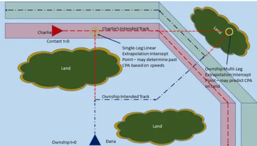
Figure 1-2: Illustration of the current state of risk collision analysis tools provided onboard marine vessels for the problem statement scenario. Ownship vessels assume contacts maintain current course and speed until an observed change. Advances in voyage management systems provide extrapolation with ownship (Dana) multi-leg maneuvers but will maintain the contact (Charlie) course and speed. Analysis tools will not account for the existence of traffic lanes or land and will predict risk of collision and danger rings on land.
at the point of intersection.
When this same scenario occurs on manned vessels, current ARPA tools and other navigational aids do not account for target vessel maneuvers and use the assumption that targets maintain current course and speed. These scenarios require ship officer experience and intuition to evaluate expectations of target vessels and render all the onboard electronic aids less than ideal during the interaction time. This problem is further complicated by the proximity to the traffic lanes at the time of critical decision making when such speed - and potentially course - maneuvers would be required.
1.3
Nautical Rules of the Road
The following COLREGs rules are for all vessels in sight of one another and apply during open ocean operations [7, 27]:
∙ Rule 13 - Overtaking: ’any vessel overtaking any other shall keep out of the way of the vessel being overtaken’
Figure 1-3: Problem statement scenario with Dana seeking to join the TSS and negotiating entrance with Charlie and Echo contacts in opposite directions. In this scenario, Dana should determine a requisite speed to create a safe distance from both vehicles while crossing the path of Charlie and potentially crossing in front (or behind) of Echo. As traffic density in both lanes increase, it becomes more challenging to determine a speed that minimizes contact density at the point of intersection.
∙ Rule 14 - Head-On Situation: ’when two power-driven vessels are meeting on reciprocal or nearly reciprocal courses so as to involve risk of collision each shall alter her course to starboard so that each shall pass on the port side of the other’
∙ Rule 15 - Crossing Situation: ’when two power-driven vessels are crossing so as to involve risk of collision, the vessel which has the other on her own starboard side shall keep out of the way ("give way") and shall, if the circumstances of the case admit, avoid crossing ahead of the other vessel’
∙ Rule 16 - Actions for a Give Way Vessel: ’take early and substantial action to keep well clear’
∙ Rule 17 - Actions for the Stand-On Vessel: ’may take action to avoid collision if it becomes clear that the give-way vessel is not taking appropriate action’ Ships operating within a traffic separation scheme are in accordance with COL-REGs Rule 10. A typical TSS is illustrated below in Figure 1-4. Behaviors of partic-ular interest to autonomous vehicles are cited in the following [7]:
any vessel of her obligation under any other rule’
∙ Rule 10.b - ’a vessel using a traffic separation scheme shall:
– proceed in the appropriate traffic lane in the general direction of traffic flow for that lane
– so far as practicable keep clear of a traffic separation line or separation zone
– normally join or leave a traffic lane at the termination of the lane, but when joining or leaving from either side shall do so at as small an angle to the general direction of traffic flow as practicable’
∙ Rule 10.c - ’a vessel shall, so far as practicable, avoid crossing traffic lanes but if obliged to do so shall cross on a heading as nearly as practicable at right angles to the general direction of traffic flow’
Figure 1-4: Traffic Separation Scheme - General Idea
1.4
Literature Review
In previous works [10, 2], multi-objective optimization was used to demonstrate safe COLREGs-compliant collision avoidance in open ocean scenarios in which inten-tions of the autonomous vessel are relayed by deliberate ship maneuvers that serve
to communicate understanding of the relevant COLREGs Rules 13-17 and compli-ance with required actions. This study looks at Rule 10 of the COLREGs that has not been previously examined for autonomous vehicles. In the marine domain, Rule 10 discusses the changes in operations that occur within traffic separation schemes (TSS). Vessels within a TSS have well-regulated transit lanes which can create more predictable travel patterns. Additionally, there are hazards to navigation such as prox-imity to land, required waypoint turns, requirements on entry and exit, and proxprox-imity to vessels such as ferries that cross traffic schemes that require different maneuvers than those observed in open ocean. As stated before, autonomous vehicles would ex-ecute open ocean collision avoidance maneuvers with both course and speed maneu-vers to prevent risk of collision using current COLREGs-compliant collision avoidance algorithms. Such maneuvers in a TSS or in the inshore traffic zone (ITZ) would com-municate improper intentions to human-operated vessels where speed maneuvers are more prevalent and different course decisions would be expected. Conversely, vehicles operating in the TSS under similar algorithms might execute maneuvers that would exit the TSS due to stand-on and give-way assumptions. In specific scenarios, such as ferry crossings, the COLREGs would require the ship give way for other ships on their starboard side. Typically, ferries normally give way for all traffic or delay their departure to create an opening to transit across traffic flow. In other scenarios, ship officers of through traffic conduct speed maneuvers to facilitate creating the opening for ferries. These behaviors have no documented support in COLREGs and may cause misunderstanding between human operators and autonomous vehicles without addressing the change in environment [23]. AIS was implemented to prevent this mis-understanding by transmitting destinations between manned vessels. The usage of inter-vehicle communication in this study proposes that transmitting intended routes between vehicles allows for calculation of vehicle trajectories and collision avoidance maneuvers in place of assumptions of stand-on/give-way vessel maneuvers.
1.4.1
Fuzzy Logic Usage for Collision Avoidance in Vessel
Traf-fic Service
Fuzzy logic mathematics is way to represent vague, sparse, and imprecise infor-mation in mathematical models. Fuzzy logic has been used to quantify dangerous situations by coupling collision probabilities derived from simulated data and field studies of navigational collisions, groundings, and accidents with fuzzy logic prob-ability sets. Fuzzy probprob-ability sets were used to capture unfavorable navigational situations and distances in which accidents had a probability of occurring but may not have and the incident went unregistered. Studies utilized the fuzzy logic method to quantify ships maneuvering around bends in waterways such as in Figure 1-5. In the scenario, grounding probabilities and distances to the extremes of the waterways were analyzed to determine fuzzy events. Fuzzy logic method was later applied to
Figure 1-5: Navigational Area of the Single Bend Divided into Sections to determine fuzzy events [8]
vessels operating in a vessel traffic service that has navigational constraints and, in some cases, traffic separation schemes. Fuzzy logic coupled probabilistic collision risk with the generation of guarding rings around vessels. The contribution of this ap-plication was used to provide an alert monitoring system for VTS monitoring and decision making to predict potential collisions. In this method, a fuzzy system used AIS dynamic data (such as ship size and speed) along with static information like sea state to calculate the range of the guarding ring and the value of the danger index [0,1]. Additionally, fuzzy logic was applied to critical collision scenarios covered by
Rule 17.a.ii of the COLREGS in which the give way vessel fails to take appropriate actions and the stand on vessel is required to make extremis maneuvers to avoid col-lision. The method then calculated collision encounters using vessel velocity, turning rate, turning direction, and a desired passing distance as variables [[8], [9], [22]].
(a) The radial axis of two guarding rings (b) Typical architecture of a fuzzy system Figure 1-6: Modelling of the Fuzzy Guarding Rings [9]
In this thesis, the process of determining probabilistic collision risk is replaced with the generation of sets of extrapolation points and coupling that to guarding rings. This study determines collision risk using contact waypoints, contact speed, ownship waypoints, and stand-off distance as variables to determine a safe ownship speed to reduce collision risk using the application pSegListIntercept in Chapter 3.
1.4.2
Evolutionary Sets of Safe Ship Trajectories within
Traf-fic Separation Schemes
While fuzzy logic was used to quantify potential collisions, other studies focused on determining safe trajectories to avoid collision. An early approach was to use evolu-tionary algorithms and fuzzy logic probability to determine ownship trajectories [24]. Later approaches by Szlapczyński focused on combining portions of game theory with evolutionary algorithms called evolutionary sets of safe ship trajectories (ESoSST). The multi-ship scenario treated each ship as a differential game in which each par-ticipant possessed their own strategy for success. Early evolutionary algorithms then searched through permutations of possible solutions to obtain global optimizations against a fitness function. Game theory scenarios would predict target maneuvers and
calculate own ship trajectory as the input solution. Evolutionary algorithms would generate a coupled set of optimized trajectories that worked all ships involved in an encounter while avoiding collisions. The application of this method was for VTS mon-itoring and on-board collision avoidance systems. This was computationally powerful but required targets to maintain course and speed or new ownship trajectories would need to be recalculated. Later the author utilized advances in evolutionary algorithms by use of evolutionary operators that enhanced results and allowed removal of target maneuver constraints [25, 26]. Similar to genetic algorithms, the inclusion of special-ized operators sped up the evolutionary process while generating a diverse population and a vast space of solutions to search. This could now account for vessels maneu-vering in restricted waters in which maintaining course and speed was impractical or resulted in grounding or navigationally unsafe conditions.
(a) Evolutionary Algorithm - General [26] (b) Evolutionary Algorithm - ESoSST [27] Figure 1-7: Modelling of Evolutionary Algorithms
In 2013, Szlapczyński noted that the TSS problem had not been investigated thoroughly and added additional Rule 10 operators [27]. These operators were used to detect TSS violations and penalize the fitness function accordingly. Violations were categorized into three groups:
∙ Inshore Traffic Zone Violations (region between nearby coastal shore and traffic lane)
∙ Violations of the Separation Zone (regulated space between traffic lanes) ∙ Violations of the Traffic Lane
– Assumed to be a 10∘ difference between the ship’s heading and the lane’s direction for transiting through
– Assumed to be a 10∘ difference from the lane perpendicular for vessels crossing the lane
– Assumed to be a 20∘difference at the lane entrance/exit and ship’s heading More recently, Szlapczyński added a new decision element for operating within a traf-fic separation scheme which optimized against speed reduction maneuvers illustrated in the flowchart in Figure 1-8 [28]. He noted that within a TSS, there are shorter distances between vessels in which course alterations may be insufficient alone, large maneuvers may be the improper signal to other ship operators, and there is a re-duction in the detection time for ship maneuvers. This resulted in a new set of ship trajectories that also accounted for a speed reduction to avoid collision.
This thesis intends to utilize the operators of TSS violations - specifically the vehicle
Figure 1-8: ESoSST Method with Speed Reduction Flowchart [28]
course while transiting through and crossing traffic lanes - to allow vehicles iden-tify their status and compliance with Rule 10. This definition is then turned into a message passed by inter-vehicle communications for classifying TSS contacts by the
application pTSSCompliance.
1.5
Contributions of this Work
Applications of the algorithms presented could also be applied to current human navigation voyage management aids and ARPA tools or for use in a stand alone decision aid to better inform ship officers during traffic separation operations. This work presents new algorithms and applications to the COLREGSs-compliant library that can further enable autonomous vessels to operate in closer inland waters where the current state of practice is to have manual or remote operations in waters close to the pier and then transition to full autonomy in open ocean. This thesis seeks to understand the complexity in generating and communicating traffic separation schemes to vehicles and creating an instance on board using using Mission Oriented Operating Suite - Interval Programming (MOOS-IvP) software. Applications and behaviors are presented for modeling the Traffic Separation Scenario in the MOOS-IvP autonomy software in order to demonstrate predictive solutions and generate experimental results.
1.6
Scope and Assumptions
The scope of this thesis focuses on the collision avoidance speed maneuver from a vehicle seeking to join a TSS and assumes that vessels operating in the traffic lane will execute motions in accordance with waypoints and speeds passed during vehicle communications. Because waypoints are shared, a maneuver intention trajectory es-timation is used with discrete trajectories [11] to determine discrete intercept points and determine time horizon of interception. Additionally, intent can be derived from adherence to traffic lanes and communication of destination. The proposed algo-rithms assume intent information is obtained through inter-vehicle communications with unlimited range and without faulty communications.
1.7
Objectives and Approach
The objective of this thesis is to build a multi-leg predictive analysis tool that recommends safe speed to minimize contact density for vehicles joining a traffic sep-aration scheme. Additionally, this thesis intends to create a method to generate a traffic separation scheme onboard a vessel via message passing vice pre-loading har-bor coordinates. There is no known work to date on unmanned systems to generate COLREGs-compliant collision avoidance specifically for Rule 10. This thesis proposes algorithms for over-the-horizon speed prediction that minimizes collision risk based on the intent and adherence to traffic separation schemes by nearby contacts coupled with COLREGs Rule 10 constraints. The thesis has the following approach:
∙ Provide background information about vessel traffic services and traffic separa-tion schemes
∙ Development of structures and algorithms to digitally recreate a traffic separa-tion scheme on a shoreside applicasepara-tion based on Title 33 CFR
∙ Development of a method to pass traffic separation scheme messages to vehicles and generate scheme onboard for close inland water usage
∙ Development of a Traffic Separation Scheme scenario and identification of method to pass compliance intent between vessels
∙ Develop a baseline non-compliant scenario as a basis for comparison
∙ Develop an algorithm to predict traffic density, points of interest, and safe speed for a vessel entering/exiting the traffic scheme
∙ Evaluation of the proposed collision avoidance applications through simulations using separation distance between vehicles as a metric for success
Chapter 2
Vessel Traffic Services and Traffic
Separation Schemes
2.1
Code of Federal Regulations
The rules, regulations, definitions, and governing authorities for vessel traffic ser-vices and traffic separation schemes are outlined in the Code of Federal Regulations, Title 33 - Navigation and Navigable Waters (33 CFR) [4] [5]. The CFR is a collection of governing laws, divided into 50 broad subject titles, updated annually, and pub-lished in the Federal Register by various agencies of the federal government. Federal departments responsible for Title 33 include:
∙ Chapter 1: United States Coast Guard (USCG) / Department of Homeland Security
∙ Chapter 2: Army Corps of Engineers / Department of the Army, DoD
∙ Chapter 4: St. Lawrence Seaway Development Corporation / Department of Transportation
33 CFR Chapter 1, Subchapter P - Ports and Waterways Safety - contains the im-plementation of the regulations identified in the Ports and Waterways Safety Act of 1972. This act authorizes the USCG to create vessel traffic services and traffic separation schemes for ports, harbors, and other waters under the jurisdiction of the United States that are subjected to congested vessel traffic [29].
2.2
Vessel Traffic Services
Vessel Traffic Services and Vessel Movement Reporting Systems (VMRS) are de-fined in Subchapter P: Part 161 of Title 33. Per 161.1(a), this service is provided to "enhance navigation, vessel safety, marine environmental protection, and promote safe vessel movements"[5]. A VTS provides safe, efficient marine vessel traffic and collision prevention by collecting, coordinating, and disseminating traffic information and continuous monitoring and management of vessel traffic. There are 12 service centers designated in the United States as defined in Part 161.12 and regulated by the USCG, but the operations of each center are not standard. Geographical constraints, geographical location, traffic density conditions, and regional legislation means that each VTS provides a similar service but potentially accomplished in a different way. According to the Puget Sound VTC User’s Manual (2019) [33], management consists of monitoring, informing, recommending, and directing (on rare occasions and height-ened security). In contrast, the New York VTS User’s Manual (2019) [32] also states that it manages traffic by informing, monitoring, and recommending, but explicitly states that it "does not direct the maneuvering of a vessel".
Title 33 still maintains that the overall responsibility for ship safety remains with the ship’s officer but VTS may inform and issue directions to vessels to minimize risk of collision and supervise movements within a VTS area. Much of the research discussed in Section 1.4 into VTS and TSS creates a solution or tool for use by a VTS center to create a global set of solutions for traffic inside a TSS and coordinate traffic patterns to minimize risk.
2.3
Traffic Separation Schemes
Traffic Separation Schemes, defined in 33 CFR Part 167 Subpart A are established to provide access routes into and out of US ports by the means of separating opposing streams of traffic [5]. Vessels operating inside of a TSS operate in accordance with Rule 10 of the COLREGs. There are specific instances of two-way traffic but a typical
TSS is primarily composed of separated one way schemes with the following objects: ∙ One way traffic lanes - typically defined by a set of coordinates that establishes
the boundary between the traffic lane and the inshore traffic zones
∙ Separation zones or lines - a set of coordinates which are used to provide sepa-ration and distinction between the opposing traffic lanes
∙ Precautionary Areas - a set of coordinates or a provided coordinate and associ-ated radius used as a routing tool that identifies areas in which ship officers must navigate with precaution usually due to branching, joining, or exiting traffic or expected course maneuvers
33 CFR Part 167 Subpart B contains the geographical coordinate description of all the traffic separation schemes in the US as referenced using the North American 1927 Datum (unless specifically stated otherwise). An example TSS (Figure 2-1), such as Puget Sound and its approaches: Puget Sound (33 CFR 167.1323) is provided as a collection of six separation zones and two traffic lanes connected by six precautionary areas. An excerpt from the Puget Sound TSS list of the items is are provided below [5]:
(a) A separation zone bounded by a line connecting the following geographical po-sitions (letters provided for reference in Figure 2-2):
Latitude Longitude (A) 48∘11.08’N 122∘46.88’W (B) 48∘06.85’N 122∘39.52’W (C) 48∘02.48’N 122∘38.17’W (D) 48∘02.43’N 122∘38.52’W (E) 48∘06.72’N 122∘39.83’W (F) 48∘10.82’N 122∘46.98’W
(b) Precautionary area "SC" which is contained within a circle of radius 0.62 miles, centered at 48∘01.85’N, 122∘38.15’W (see Figure 2-3).
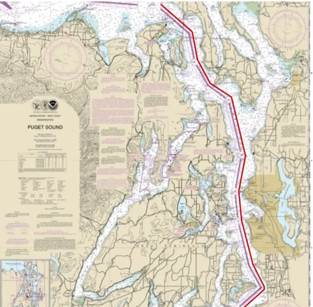
Figure 2-1: NOAA Chart 18440 displaying the Traffic Separation Schemes for the Puget Sound Region. This type of chart is a freely-available chart expected to be carried by ship navigators onboard.
"SC", "SE", "SF", "SG", "T", and "TC" as described in paragraphs (b), (d), (f), (h), (j), and (k) of this section, respectively, and is located between the separation zones described in paragraphs (a), (c), (e), (g), (i), and (k) of this section, respectively, and a line connecting the following geographical positions (see Figure 2-4): Latitude Longitude 48∘11.72’N 122∘46.83’W 48∘07.13’N 122∘38.83’W 48∘02.10’N 122∘37.32’W 47∘58.23’N 122∘34.07’W 47∘55.83’N 122∘28.80’W 47∘45.92’N 122∘25.33’W 47∘39.68’N 122∘26.95’W 47∘34.65’N 122∘26.18’W 47∘27.13’N 122∘23.40’W 47∘23.33’N 122∘20.37’W 47∘22.67’N 122∘20.53’W 47∘19.07’N 122∘26.75’W
Figure 2-2: NOAA Chart 18440 Separation Zone. Letters on the chart correspond to the coordinates in 33 CFR 167.1323.a for a separation zone in the Puget Sound TSS. The separation zone is highlighted in red.
Figure 2-3: NOAA Chart 18440 Precautionary Area. The highlighted region corre-sponds with details specified in 33 CFR 167.1323.b for a precautionary area in the Puget Sound TSS identified as "SC".
Figure 2-4: NOAA Chart 18440 illustrating the line that connects the coordinates in 33 CFR 167.1323.m. and bounding the northbound transit lane.
Chapter 3
Implementing the Traffic Separation
Scheme Scenario in MOOS-IvP
In order to evaluate the response of vehicles operating in a TSS, a baseline scenario was established in MOOS-IvP. MOOS-IvP utilizes message passing between processes and applications within a publish-subscribe architecture similar to Robot Operating System (ROS) or Micro Air Vehicle Link (MAVLink). This architecture has a star-like topology (Figure 3-2) in which each participant in the scenario runs a stand-alone collection of of MOOS applications called a community. Applications and processes within a MOOS community publish and subscribe to variable-value pairs stored within the community Mission Oriented Operating Suite - Database (MOOSDB) [16, 15, 17]. MOOS-IvP applications have been used primarily - but not exclusively - in the marine domain. The TSS scenario begins with a vehicle operating outside the traffic lane in the ITZ with a planned track to cross the inbound lane and use the outbound lane for transit.
3.1
Launching the Baseline TSS Scenario
The baseline scenario is the simulation scenario without additional applications and behaviors to alter simple waypoint following behaviors. It can be viewed by the user via a GUI application called pMarineViewer and is launched from the command
line. It has TSS traffic lane vehicles starting in the inbound (red) and outbound (green) lanes that operate in accordance with Rule 10 and transit accordingly. There are two separate command line arguments in the launch script that allow the user to increase the number of simulated traffic vessels in the inbound and outbound lanes individually. Additionally there is a time warp argument at the end that allows a mission to be sped up. Starting positions within the lane polygons and vessel speeds are picked at random.
$ ./launch.sh --in=2 --out=3 5
The scenario has a joining vehicle begin in a start area outside of the lanes with intentions to cross the inbound lane and join the outbound lane traffic. The baseline scenario without arguments is a three vehicle interaction between a joining vehicle and two transiting vessels (one in each lane), similar to the geometry seen in Figure 3-1.
The TSS Scenario creates a MOOS-IvP community called shoreside that serves as the simulated harbor traffic or VTS system in place to monitor marine traffic. A second community called usv is created for the joining vehicle with subsequent com-munities generated for the traffic lane vessels. Each community runs a MOOSDB application that allows distinct applications in that community to communicate by mapping variable names to values for use within that community. The architecture of the MOOS-IvP scenario is illustrated in Figure 3-2 which shows the distribution of ap-plications between the various communities. Figure 3-3 shows a high level interaction of the applications within the scenario specifically around the digital representation of the traffic separation scheme. Figure 3-4 shows a high level interaction of the ap-plications used for speed recommendations.
Figure 3-1: TSS Scenario - Baseline Scenario. This scenario is similar to the problem statement scenario in Chapter 1. In the TSS scenario, USV is joining the TSS by crossing the paths of Abe (in the inbound lane) and Fin (in the outbound lane) and transiting in the outbound lane.
The TSS Scenario utilizes the following applications generated by the author with initial conditions summarized in Table 3.1:
1. Shoreside applications
∙ pTrafficPopulate - application for defining and generating a traffic sep-aration scheme and generating messages for vehicle use to create traffic separation schemes locally
∙ pTrafficGrade - application for producing an overall grade for the sce-nario based solely on the number of encounters for usv with other vehicles within user defined ranges
2. Vehicle applications
∙ pSegPassing - application for sharing intended waypoints to other vehi-cles
∙ pTSSCompliance - application for sharing compliance with Rule 10.b and 10.c of the COLREGs to other vehicles
∙ pSegListIntercept (joining vehicle only) - application for determining contact intersections, calculating interaction times of interest, and ulti-mately recommending a speed maneuver for the joining vessel that mini-mizes contact density at intersection points
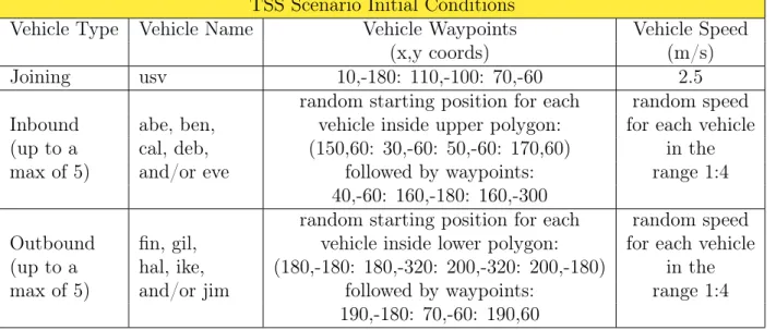
TSS Scenario Initial Conditions
Vehicle Type Vehicle Name Vehicle Waypoints Vehicle Speed
(x,y coords) (m/s) Joining usv 10,-180: 110,-100: 70,-60 2.5 Inbound (up to a max of 5) abe, ben, cal, deb, and/or eve
random starting position for each random speed vehicle inside upper polygon: for each vehicle
(150,60: 30,-60: 50,-60: 170,60) in the
followed by waypoints: range 1:4
40,-60: 160,-180: 160,-300 Outbound (up to a max of 5) fin, gil, hal, ike, and/or jim
random starting position for each random speed vehicle inside lower polygon: for each vehicle (180,-180: 180,-320: 200,-320: 200,-180) in the
followed by waypoints: range 1:4
190,-180: 70,-60: 190,60
Figure 3-3: TSS Scenario Application Interaction Map for Traffic Separation Scheme Generation. This expansion of Figure 3-2 shows which variables each application publishes (blue) and subscribes to (green) within the TSS Scenario with regards to the digital representation of the traffic separation scheme created in this study.
3.2
Traffic Separation Schemes in C++ Language
In the scenario, a series of user generated *.tss files are called. In order to repli-cate the structure in 33 CFR, each .tss file corresponds to a specific object inside a traffic separation scheme. As the scenario reads each file, it creates an object called a TrafficObject and adds each to a vector of objects that populate a TrafficScheme object. Similar to the example TSS in Section 2.3, each object is described in C++ Language for introduction into shapes recognizeable to MOOS-IvP simulation soft-ware. For simplicity in programming, the TSS Scenario uses local coordinates in the X,Y plane vice latitude and longitudinal coordinates; however, latitude and longitu-dinal reference is possible. Separation Zones (Listing 3.1) and Precautionary Areas (Listing 3.2) are described with a constraint that the provided polygon must be given as a convex input:
Figure 3-4: TSS Scenario Application Interaction Map for Speed Reduction. This expansion of Figure 3-2 shows which variables each application publishes (blue) and subscribes to (green) within the TSS Scenario with regards to the speed recommenda-tion that is generated within this study. This picture specifically shows the interacrecommenda-tion between usv and abe. In the TSS Scenario, only the joining vehicle (usv ) uses the pSegListIntercept application.
1 // = = = = = = = = = = = = = = = = = = = = = = = = = = = = = = = = = = = = = = = = = = = = = = 2 t y p e = s e p a r a t i o n z on e
3 p o l y = p o l y g o n
4 p o i n t s = 170 ,60 : 50 , -60 : 60 , -60 : 180 ,60
Listing 3.1: Example Separation Zone (*.tss file) in C++ language for the TSS Scenario 1 // = = = = = = = = = = = = = = = = = = = = = = = = = = = = = = = = = = = = = = = = = = = = = = 2 t y p e = p r e c a u t i o n a re a 3 p o l y = p o l y g o n 4 p o i n t s = x =55 , y = -60 , r a d i u s =25 5 l a b e l = SC
Listing 3.2: Example Precautionary Area (*.tss file) in C++ language for the TSS Scenario
A traffic lane (Listing 3.3) is described with the classifier "seglist" and requires ori-entation as identified by starting X,Y coordinates that are explicit in the provided
seglist: 1 // = = = = = = = = = = = = = = = = = = = = = = = = = = = = = = = = = = = = = = = = = = = = = = 2 t y p e = i n b o u n d l a n e 3 p o l y = s e g l i s t 4 p o i n t s = 150 ,60 : 30 , -60 : 150 , -180: 150 , -350 5 s t a r t = x =150 , y = -350
Listing 3.3: Example Traffic Lane Boundary Line (*.tss file) in C++ language for the TSS Scenario
Once traffic separation scheme information is transferred to digital form, there are several things that can be done with it such as generating visual aids for end user GUI applications and status determination by vehicles. A subsequent function was written in the TrafficScheme class to combine traffic lane boundary lines with pro-vided separation zone polygons to produce multiple convex polygons that collectively represent the various one way traffic lanes. Based on the number of coordinates pro-vided in the seglist boundary line, a requisite number of quadrilaterals is determined and formed by combining sequential seglist coordinate pairs with the closest adjacent separation zone polygon points for each. Visual classification and representation as inbound (red) and outbound (green) is given by the .tss "type" and follows the USCG "Red, Right, Returning" convention in the U.S Aids to Navigation System. This con-vention describes how returning vessels maintain red markers on the starboard side of the vessel [31].
3.3
Creating Traffic Lanes inside the TSS Scenario
In the scenario, shoreside uses an application called pTrafficPopulate to generate and publish the multiple convex polygons that comprise the inbound and outbound lanes. This application publishes two variables: TSS_LANESandTSS_SEP_ZONES. TSS_SEP_ZONES is a semi-colon separated string of colon separated points and TSS_LANES is a semi-colon separated string of seglist specifications. The
concate-nation of separation zone polygons and boundary seglists onboard the vehicle creates a local traffic separation scheme instance (Figure 3-5). Future versions of pTraf-ficPopulate would also pass precautionary areas and navigational hazards as other variables that could be published for vehicle use.
TSS_SEP_ZONES = pts={170,-180:170,350:180,-180};pts={50, -60:170,-180:180,-180:60,-60}... TSS_LANE = pts={200,-350;200,-180:80,-60:200,60}, label=outbound;pts=....
The practice of transmitting TSS data to vessels is currently atypical in the ma-rine domain. TSS lanes are well-defined on freely-available National Oceanic and Atmospheric Administration (NOAA) charts, described in 33 CFR, or already estab-lished on an approved Navigator’s chart pack. In the autonomous marine domain, it would be impractical to pre-load all possible polygons for all possible ports and harbors prior to launch. The process of publishing transit lanes, in general, allows vessels to dynamically register to any traffic system for the most up-to-date traffic lanes and, for autonomous vehicles, this would allow for emergency port calls. As more vessels transition away from paper charts to electronic charts, a case could be made for a similar process in the manned marine domain to ensure electronic voyage management systems and navigational aids are always operating on the most current information. Additionally, the transmission of polygons in this manner could also be used to broadcast navigational hazards, anchorage zones, and other areas of caution that could be used to dynamically change pre-planned routes for unmanned vehicles the same way that a Notice to Mariners is used by ship officers [34].
3.4
Sharing Destination Information
In the marine domain, vessels use AIS messages to pass voyage information be-tween vessels and for collision avoidance onboard. AIS transmits dynamic information (such as latitude, longitude, course, and speed) every two seconds and static infor-mation (such as ship’s name, destination, length, beam, and draught) every six
min-Figure 3-5: pTrafficPopulate AppCasting [13] Screenshot. This screenshot shows sta-tus information for the pTrafficPopulate application. In this screenshot, five polygons (two precautionary area circles and three separation zones) and two seglists are passed into the traffic scheme object as *.tss files. Given the length of the boundary line seglists (four points each), this application creates an additional six (6) traffic lane polygons (three for each seglist). Total class size for this traffic separation scheme object is eleven (11) objects. This class also assigns polygon visual properties like fill colors and edge sizes.
utes [19]. In MOOS-IvP, this information is simulated with the inter-vehicle message NODE_REPORTbut lacks the destination information. In the TSS scenario, a vehi-cle to vehivehi-cle message is generated by the pSegPassing application calledSEGLIST that passes the intended waypoints to augment the node report and fully simulate the passing of AIS destination information.
SEGLIST = vname=dana;pts={70,-30:40,-60:160,-180:160,-300}
The joining vehicle in the TSS scenario subcribes toSEGLISTandNODE_REPORT, parses both messages, and creates a vector of contacts for future calculations in the pSegListIntercept application. To enable the pSegPassing application,
adjust-ments of the existing MOOS-IvP library waypoint behavior BHV_WAYPOINT were required to have vehicles publish their individual waypoint seglist.
3.5
Sharing Traffic Separation Scheme Compliance
The application pTSSCompliance produces a string message that constantly updates the status of the vehicle compliance - or lack thereof - with COLREGs Rule 10.b and 10.c. This thesis uses two traffic separation scheme violation criteria from the ESoSSTs study [27] in Section 1.4 to determine compliance. This study evaluates entrance of the vehicle to the traffic separation scheme at locations other than the terminal ends and does not evaluate the compliance at the terminal ends. The two criteria modelled in this application:
1. A 10∘ difference between the ship’s heading and the lane’s direction for transit-ing through
2. A 10∘ difference from the lane perpendicular for vessels crossing the lane This application publishes a variable calledTSS_STATUSthat outputs a message describing the status of observing proper TSS headings and the current action of the vehicle within the TSS Scenario. One of the first checks is the initial determination of whether the current position of the vessel is located within the published traffic lanes and if the vehicle heading corresponds with the first criteria. A subsequent check determines if the current location of the vehicle is within the published separation zones. A final check looks for vehicles that are currently outside of the traffic lane and searches through the intended path to determine if the vehicle intends to cross a lane. This check determines if the approaching vessel heading is near perpendicular to the lane in accordance with the second criteria. All other vehicles are classified as "Non-Compliant/Non-Participant". Examples of the string message:
TSS_STATUS = vname=usv, status=compliant, action=transiting properly
TSS_STATUS = vname=abe, status=compliant, action=approaching the lane properly TSS_STATUS = vname=fin, status=non-compliant/non-participant
3.6
Speed Recommendation for the Joining Vehicle
The application pSegListIntercept determines contact intersections, calculates interaction times of interest, and recommends a speed maneuver for the joining vessel that minimizes contact density at points of intersect. Using the seglist information provided from each vehicle from pSegPassing, the joining vehicle, usv, is able to compare incoming seglist with the ownship seglist to determine if there are any in-tersection points. Additionally, node reports posted from each vehicle are read for associated speed information. This application then populates a ContactSegList object with contact name, speed, and seglist for each contact. A vector of these objects populate a ContactSegListSet object.
3.6.1
Determination of Intersections
This thesis uses the Faster Line Segment Calculation method described by Franklin Antonio [1] to determine if seglists intersect. This method evaluates two variables 𝛼 and 𝛽 using the x,y coordinates from the endpoints of two potential intersecting lines (Figure 3-6) against three test criteria. This application searches through ownship seglist and a contact seglist to conduct the following calculations for each leg of both:
𝛼 = (𝐵𝑦 * 𝐶𝑥) − (𝐵𝑥 * 𝐶𝑦) (𝐴𝑦 * 𝐵𝑥) − (𝐴𝑥 * 𝐵𝑦) (3.1) 𝛽 = (𝐴𝑥 * 𝐶𝑦) − (𝐴𝑦 * 𝐶𝑥) (𝐴𝑦 * 𝐵𝑥) − (𝐴𝑥 * 𝐵𝑦) (3.2) where: 𝐴𝑥,𝑦 = (𝑥, 𝑦)2− (𝑥, 𝑦)1 𝐵𝑥,𝑦 = (𝑥, 𝑦)3− (𝑥, 𝑦)4 𝐶𝑥,𝑦 = (𝑥, 𝑦)1− (𝑥, 𝑦)3
This method has the following three checks:
1. Ensure the denominator (𝐴𝑦 * 𝐵𝑥) − (𝐴𝑥 * 𝐵𝑦) is not zero. If the denominator is zero, the two segments are colinear.
2. Both 𝛼 and 𝛽 must have the same sign 3. Both 𝛼 and 𝛽 must be on the interval [0,1]
If all three are satisfied, then the line segments intersect. If it is determined that an intersection occurred, the equation to determine the actual intersection point P(x,y) is given by the following:
𝑃𝑥,𝑦 = (𝑥, 𝑦)1+ 𝛼 * ((𝑥, 𝑦)2− (𝑥, 𝑦)1) (3.3)
The Faster Line Segment Intersection method is effective for determining when line segments intersect but is not effective in scenarios in which one line segment terminates on the other such as in Figure 3-7. This geometry situation is equally important in the vehicle domain. This particular geometry is present in the TSS Scenario where usv has a line segment that terminates on any outbound vehicle line segment before joining the outbound lane. Franklin’s calculation misses this important intersection point. An additional check was added to determine instances in which a line segment terminates on the other and adds the resultant coordinates to the vector of calculated intersection points. One of the limitations of this study is that the inclusion of this second check results in a duplication of answers when the intersection point is the terminal end for both line segments (Figure 3-8). Future versions implementing this process would look to eliminate duplicate answers.
In the TSS Scenario, starting position and starting speed are randomized to the vehicles in the traffic lane but they share the same waypoints. Each vessel is ideal-ized with a heading down the center of each lane polygon. This provides the added ability of being able to verify proper calculation of intersection points shown in the pSegListIntercept application in Figure 3-9 with Table 3.2.
Figure 3-6: Intersecting Lines - Generic Case. The Faster Line Segment Intersection calculation by Franklin [1] is robust to this case. In this case, the two line segments intersect completely.
Ownship Seglist Contact Seglist Resultant
Intersection Points 10,-180: 110,-100: 70,-60 rand start, 40,-60: 160,-180: 160,-300 93.33, -113.333 10,-180: 110,-100: 70,-60 rand start,190,-180: 70,-60: 190,60 110.00,-100.00
70, -60 Table 3.2: Resultant Intersection Points of the TSS Scenario. As discussed earlier, the resultant answer is the intersection point with the inbound vehicle, the outbound vehicle, and the shared waypoint (70, -60) of usv and the outbound vehicle.
3.6.2
Extrapolation of Discrete Points for Contacts
Now that intersection points are generated for the joining vessel, usv, a quick algorithm calculates the length of usv ’s seglist to each of the intersection points along the seglist. Combined with usv ’s speed, a time until intersection is determined. Once armed with time, an extrapolation of scenario contacts can be calculated. Since each object in the ContactSegList class has a contact speed and a vector of seglists, a time on each seglist by the contact can be determined. An algorithm was generated which takes an input variable of time (from usv ), determines the appropriate seglist in the ContactSegList, and calculates an associated point along the contact seglist
Figure 3-7: Intersecting Lines - Case with a Terminal Endpoint on the Other Line. This is the geometry in which the Faster Line Segment Intersection calculation fails to generate an intersection point. This study added a subsequent check for these points because they are points of interest to this study.
that corresponds to that time at the contact speed (Listing 3.4). This function is a simple displacement calculation given by the following:
𝑥1 = 𝑥0+ (𝑐𝑜𝑠(ℎ𝑒𝑎𝑑𝑖𝑛𝑔) * 𝑣𝑒𝑙𝑜𝑐𝑖𝑡𝑦 * 𝑡𝑖𝑚𝑒) (3.4)
𝑦1 = 𝑦0+ (𝑠𝑖𝑛(ℎ𝑒𝑎𝑑𝑖𝑛𝑔) * 𝑣𝑒𝑙𝑜𝑐𝑖𝑡𝑦 * 𝑡𝑖𝑚𝑒) (3.5)
where:
𝑥0, 𝑦0 = The beginning x,y coordinate for the relevant contact leg
𝑥1, 𝑦1 = The final x,y contact coordinate based on the amount of time on the leg
velocity = Contact velocity
time = Time of interest. This is the time that usv reaches the intersection point
This application assumes that contacts are travelling on the associated heading for future legs and assumes that speed remains constant. Additionally, no adjustments are made for turning radius or turning speeds in the calculation of time or associated extrapolation points in the future.
Figure 3-8: Intersecting Lines - Case with Similar Terminal Endpoints by Both Lines. This geometry produces duplicate answers in this study because both checks find this answer. In the TSS Scenario, this means that usv and all the outbound vehicles should show duplicate answers at their shared waypoints throughout.
Figure 3-9: pSegListIntercept AppCasting [13] Screenshot Verifying Calculations. This TSS Scenario run contains usv as the joining vehicle. Inbound contacts are abe and ben. Outbound contacts are fin and gil. This screenshot captures a verification of the calculations of intersection points from Table 3.2. In this scenario, shared way-points with usv are captured by both methods of calculation and produces duplicate answers (70,-60) as discussed in Figure 3-8.
1 X Y P o i n t m _ l o c a t e ; 2 // -3 // P r o c e d u r e : p r e d i c t _ p o i n t 4 v o i d S e g L i s t C o n t a c t :: p r e d i c t _ p o i n t (d o u b l e t i m e ) 5 { 6 if( m _ g o t _ s p d ) { 7 for(int i =0; i < m _ l e g _ s e g l i s t . s i z e () ; i ++) { 8 d o u b l e t i m e _ r e m a i n = 0; 9 d o u b l e h e a d i n g = 0; 10 if( t i m e <= m _ t i m e _ l e g [ 0 ] ) { 11 t i m e _ r e m a i n = t i m e ; 12 m _ l o c a t e . s e t _ l a b e l (" v n a m e = " + m _ v n a m e + " ; h e a d i n g = " + d o u b l e T o S t r i n g ( m _ l e g _ h e a d i n g [ 0 ] ) ) ; 13 h e a d i n g = m _ l e g _ h e a d i n g [ 0 ] ; 14 p o i n t C a l c u l a t e ( m _ l e g _ s e g l i s t [0] , heading , t i m e _ r e m a i n ) ; 15 m _ g o t _ p r e d i c t = t r ue; 16 r e t u r n; 17 } 18 e l s e if(( t i m e <= m _ t i m e _ l e g [ i ]) && ( t i m e > m _ t i m e _ l e g [ i - 1 ] ) ) { 19 t i m e _ r e m a i n = t i m e - m _ t i m e _ l e g [ i - 1 ] ; 20 m _ l o c a t e . s e t _ l a b e l (" v n a m e = " + m _ v n a m e + " ; h e a d i n g = " + d o u b l e T o S t r i n g ( m _ l e g _ h e a d i n g [ i ]) ) ; 21 h e a d i n g = m _ l e g _ h e a d i n g [ i ]; 22 p o i n t C a l c u l a t e ( m _ l e g _ s e g l i s t [ i ] , heading , t i m e _ r e m a i n ) ; 23 m _ g o t _ p r e d i c t = t r ue; 24 r e t u r n; 25 } 26 } 27 } 28 } 29 // -30 // P r o c e d u r e : p o i n t C a l c u l a t e 31 v o i d S e g L i s t C o n t a c t :: p o i n t C a l c u l a t e ( X Y S e g L i s t seglist , d o u b l e heading , d o u b l e t i m e _ r e m a i n i n g ) 32 { 33 d o u b l e x1 = s e g l i s t . g e t _ v x (0) ;
34 d o u b l e y1 = s e g l i s t . g e t _ v y (0) ; 35 d o u b l e h d g c o n v e r t = a n g l e 1 8 0 (90 - h e a d i n g ) ; 36 d o u b l e r a d h d g = d e g T o R a d i a n s ( h d g c o n v e r t ) ; 37 d o u b l e x = x1 + (( cos ( r a d h d g ) ) * m _ n a v _ s p d * t i m e _ r e m a i n i n g ) ; 38 d o u b l e y = y1 + (( sin ( r a d h d g ) ) * m _ n a v _ s p d * t i m e _ r e m a i n i n g ) ; 39 m _ l o c a t e . s e t _ v e r t e x ( x , y ) ; 40 }
Listing 3.4: Function predict_point() and pointCalculate() from the SegListContact class
3.6.3
Final Speed Recommendation
Given the discussed initial conditions, a speed recommendation is given to the joining vehicle inside the pSegListIntercept application. At this point, the process has produced two key pieces of information: the intersection point and the associ-ated contact points for that intersection. This application allows the user to define a guarding ring range to maintain contacts outside of. The goal is to determine the number of extrapolated contact points that occur inside of this guarding ring at each of the intersection points. A final algorithm was written to search through a range of speeds and return a speed that coincides with the least amount of limiting con-tacts (concon-tacts within the guarding ring range). The following function predictSpeed() (Listing 3.5) occurs inside the pSegListIntercept application. This function gen-erates a WPT_UPDATE message to the existing waypoint following behavior that adjusts the speed of the joining vehicle. The speed recommendation is based on find-ing the speed associated with the global minimum number of limitfind-ing contacts inside the user-defined guarding ring at all of the calculated intersection points. An example status of this application is shown below in Figure 3-10.
1 v o i d S e g L i s t I n t e r c e p t :: p r e d i c t S p e e d () 2 {
3 d o u b l e s p e e d _ g u e s s = m _ i n p u t _ s p e e d ; 4 if( m _ e x t r a _ r e a d y ) {
6 // T h i s for l o o p s e t s the s p e e d g u e s s b e t w e e n a min and max r a n g e . 7 // A r a n g e [1 ,3.5] was c h o s e n to p r e v e n t a h i g h s p e e d or s l o w s p e e d 8 // s o l u t i o n t h a t c r e a t e s a t r i v i a l s c e n a r i o 9 // N O T E : R e c o m m e n d e d to NOT h a v e a m i n _ s p e e d of z e r o 10 11 s p e e d _ g u e s s = s ; 12 vector <double> m _ l e n g t h ; 13 vector <double> m _ t i m e ; 14
15 // S t e p 1: For e a c h of the c o n t a c t s e g li s t s , d e t e r m i n e all the 16 // i n t e r c e p t p o i n t s ( g e t _ p x and g e t _ p y ) . O n c e you h a v e 17 // the i n t e r c e p t points , d e t e r m i n e the t i m e of i n t e r e s t
18 // for the j o i n i n g v e h i c l e u n t i l the i n t e r c e p t p o i n t . 19 // The f u n c t i o n b i t e S e g L i s t r e t u r n s the r e m a i n i n g s e g l i s t 20 // f r om the b e g i n n i n g u n t i l the i n t e r c e p t p o i n t for the 21 // f i r s t a r g u m e n t s e g l i s t . In t h i s case , the 22 // j o i n i n g v e h i c l e ( o w n s h i p ) 23 24 for(int l =0; l < m _ o s _ i n t e r c e p t . s i z e () ; l ++) { 25 X Y S e g L i s t r e m a i n i n g = b i t e S e g L i s t ( m _ o s _ s e g l i s t , m _ o s _ i n t e r c e p t . g e t _ p x ( l ) , m _ o s _ i n t e r c e p t . g e t _ p y ( l ) ) ; 26 d o u b l e l e n g t h = r e m a i n i n g . l e n g t h () ; 27 m _ l e n g t h . p u s h _ b a c k ( l e n g t h ) ; 28 d o u b l e t i m e = l e n g t h / s p e e d _ g u e s s ; 29 m _ t i m e . p u s h _ b a c k ( t i m e ) ; 30 } 31
32 // S t e p 2: For e a c h of the i n t e r e s t t i m e s ( vector < double > m _ t i m e ) , 33 // e x t r a p o l a t e p o i n t s for all the c o n t a c t s p o p u l a t e d 34 // in C o n t a c t S e g l i s t S e t ( m _ t s s _ c o n t a c t s ) .
35 // For e a c h contact , the S e g L i s t C o n t a c t f u n c t i o n 36 // . e x t r a p o l a t e _ p o i n t ( t i me ) s e a r c h e s t h r o u g h
37 // e a ch leg ( c o n t a c t le g s e a c h h a v e a max t i m e on leg 38 // b a s e d on c o n t a c t s p e e d as p a r t of the C o n t a c t S e g L i s t 39 // o b j e c t ) , f i n d s the leg of i n t e r e s t , c a l c u l a t e s a 40 // r e m a i n i n g t i m e on leg , and t h e n c a l c u l a t e s a x , y

![Figure 1-5: Navigational Area of the Single Bend Divided into Sections to determine fuzzy events [8]](https://thumb-eu.123doks.com/thumbv2/123doknet/14129274.468856/29.918.288.629.547.740/figure-navigational-area-single-divided-sections-determine-events.webp)