Publisher’s version / Version de l'éditeur:
ASTM Special Technical Publication, 422, pp. 5-20, 1967-12-01
READ THESE TERMS AND CONDITIONS CAREFULLY BEFORE USING THIS WEBSITE.
https://nrc-publications.canada.ca/eng/copyright
Vous avez des questions? Nous pouvons vous aider. Pour communiquer directement avec un auteur, consultez la première page de la revue dans laquelle son article a été publié afin de trouver ses coordonnées. Si vous n’arrivez pas à les repérer, communiquez avec nous à [email protected].
Questions? Contact the NRC Publications Archive team at
[email protected]. If you wish to email the authors directly, please see the first page of the publication for their contact information.
NRC Publications Archive
Archives des publications du CNRC
This publication could be one of several versions: author’s original, accepted manuscript or the publisher’s version. / La version de cette publication peut être l’une des suivantes : la version prépublication de l’auteur, la version acceptée du manuscrit ou la version de l’éditeur.
Access and use of this website and the material on it are subject to the Terms and Conditions set forth at
Load and fire test data on steel-supported floor assemblies
Pearce, N. S.; Stanzak, W. W.
https://publications-cnrc.canada.ca/fra/droits
L’accès à ce site Web et l’utilisation de son contenu sont assujettis aux conditions présentées dans le site
LISEZ CES CONDITIONS ATTENTIVEMENT AVANT D’UTILISER CE SITE WEB.
NRC Publications Record / Notice d'Archives des publications de CNRC:
https://nrc-publications.canada.ca/eng/view/object/?id=c270b2d9-4a7c-43dd-8079-c67ab0eaa1fc https://publications-cnrc.canada.ca/fra/voir/objet/?id=c270b2d9-4a7c-43dd-8079-c67ab0eaa1fcN .
S . Pearce' and W . W . Stanzak2Load and Fire Test Data on Steel-
Supported Floor Assemblies
REFERENCE: N. S. Pearce and W. W. Stanzak, 'Zoad and Fire Test Data on Steel-Supported Floor Assemblies," Symposium on Fire Test
Methods-Restraint & Smoke 1966, ASTM STP 422, Am. Soc. Testing
Mats., 1967, p. 5.
ABSTRACT: Information gained from standard load and fire tests on eleven steel-supported constructions is presented. A n elastic analysis of a n idealized composite steel-concrete beam is developed, and a definition for the degree of composite action inherent in test specimens is proposed. The restraint afforded by the test frame and its importance to continued composite action during the fire test are examined. The degree of com- posite action is calculated for a number of assemblies, and the mecha- nism of load failure during fire test is discussed briefly. Using this infor- mation, some aspects of present fire test practics are examined and possible improvements are suggested.
KEY WORDS: fire tests, steel construction, reinforced concrete, failure, thermal expansion, restraint
Nomenclature
Cross-sectional area of steel beam
Transformed cross-sectional area of composite beam Equivalent effective width of concrete slab
Degree of composite action Effective depth of concrete slab
Distance from top of slab to centroid of steel beam Depth of steel beam
Overall depth of structural system
Height of neutral axis from lower flange of steel beam
Height of neutral axis from lower flange of beam-floor assembly Moment of inertia of beam-floor assembly
Moment of inertia of floor
Assistant chief engineer, Underwriters' Laboratories of Canada, Scarborough, Ont., Canada.
=Steel industries fellow, Division of Building Research, National Research Council, Ottawa, Ont., Canada.
6 FIRE TEST M E T H O D S
Moment of inertia of steel beam and floor without shear connection Moment of inertia of steel beam
Moment of inertia of composite beam with full shear connection Effective span of beam
Ratio of modulus of elasticity of steel to concrete Web thickness of steel beam
Distance from top of slab to neutral axis of composite beam Extreme fiber stress at bottom of steel beam
Extrenie fiber stress at top of steel beam Stress at top of concrete slab
Live load bending moment
This paper is concerned with loading and restraint as it affects the structural performance of steel-supported floor constructions during a fire test. T h e applied loading on these structures during the fire test has been a matter for concern since fire testing began in North America.
T h e 191 8 edition of the "ASTM Standard for Fire Tests of Building Construction and Materials," which in those days went under the desig- nation ASTM C 1 9 - 18, contained the following paragraph:
The floor or roof shall be loaded in a manner to develop in each member of the construction, stresses equal to the maximum safe working stress allowed in the material of the members.
By the year 1926, the paragraph had been modified by the addition of wording which was intended to take into account the apparent imprac- ticability of fulfilling these loading requirements. T h e applicable para- graph of the standard, then numbered ASTM C 19 - 26 T , read as fol- lows:
During the fire endurance and fire stream tests, the construction shall be loaded in ii manner calculated to develop theoretically, as nearly as practicable,
the working stress in each member contemplated by the design.
T h e current edition of the standard (E 119 - 61) contains wording sub- stantially similar to this, except that reference to the fire stream test has been deleted, since this is n o longer a mandatory requirement of the standard, and the load is now specifically referred to as a superimposed load.
Discussion within ASTM Committee E 5 which is charged with the re- sponsibility for the standard has indicated that there is again a need to re- vise the test method o r interpretation of the standard, bearing in mind the manner in which this information is applied. There is an increasing tend- ency to employ information derived from fire tests out of the context of the specific assemblies tested. This is particularly true of the practice whereby beam classifications obtained from constructions which are tested as floor and ceiling assemblies arc applied to structural members which are
PEARCE A N D STANZAK ON STEEL-SUPPORTED FLOOR ASSEMBLIES 7
in no way representative of the tested assembly. It should be noted that although assemblies may appear to have basic structural similarities and similar protection, their behavior under identical temperature conditions in the standard fire test varies considerably. One reason for such varia- tion is thought to be the degree of composite action inherent in the con- struction of such assemblies. A second reason may be the variation in restraint afforded by the attachment of the floor to the support beam.
V a ~ i o u s groups participating in the work of Committee E 5 have been active in acquiring information intended to provide for greater under- standing of these problems. This paper presents the results of a study based on a series of fire tests on floor and ceiling assemblies conducted in accordance with the present requirements of the standard. The purpose of the investigation was:
1. T o study the degree of composite action inherent in beam-floor assemblies commonly submitted for fire test.
2. T o investigate the degree of restraint provided by the test frame to steel beams incorporated with various types of floor assemblies during fire tests.
3. T o examine the influence of (1) and (2) above on the structural performance of an assembly during fire tests.
T o this end, measurements were made of:
(a) Live load strains in the critical fibers of the beam during and sub- sequent to the application of the load.
(b) The strain on the frame during the fire test.
( c ) Deflections and beam temperatures throughout the test. Apparatus
Floor Furnace-The equipment used by Underwriters' Laboratories of Canada for "Fire Tests of Floor or Roof and Ceiling Constructions" consists of a test furnace designed to evaluate the performance of these constructions under fire conditions in accordance with the requirements contained in ASTM Methods E 119. The restraining frame, within the confines of which the tested assemblies are erected, consists of a welded structural steel assembly, having inside dimensions of approximately 1 8 by 14 ft. The heated volume beneath the restraining frame of approxi- mately 900 ft" is enclosed by a dry wall concrete block construction pro- tected with vermiculite plaster. A n environment following the standard time-temperature curve is produced by the controlled output of 84 natu- ral gas burners arranged in a matrix at the bottom of the furnace and supplied with combustion air through ports located below this level.
Loading System-The hydraulically operated loading equipment is designed to simulate the bending moments resulting from a uniformly distributed load applied over the floor and a linear uniform load over the support member(s). The load is applied by hydraulic jacks, mounted
8 FIRE TEST METHODS
on five separate loading units, which span the test assembly, with each loading unit controlled through a separate channel. The jacking arrange- ment provides for a total deflection at the center of the assembly of approximately 18 in. The system is designed to provide for floor load- ings of up to 450 Ib/ft"ith a maximum superimposed linear load along the support beam of 3000 lb/ft.
Deflection Gages-Floor deflections are indicated by vernier measur- ing tapes connected through a piano wire and pulley system to small counterweights located at significant locations on the surface of the assembly. The measuring tapes are calibrated to read in increments of
%
00 in.Temperature Recording-Furnace temperatures are measured by chromel-alumel thermocouples, unexposed surface temperature by iron- constantan thermocouples, arranged in accordance with the requirements of the standard and displayed on a strip chart recorder.
Strain Gages-The strains are measured by metal film, epoxy-backed, temperature compensated, strain gages having a gage length of
'/4
in. and a resistance of 120 ohms. The gages are connected in a quarter bridge, external dummy, three-wire configuration.Strain Indication-The read-out devices used with the strain gages are of two types: (1) a bridge amplifier and meter and (2) a digital strain indi- cator.
Test Assemblies
Assetnbly I-Structural steel beam, supporting equal spans of cellular steel floor units, 3 in. deep, with 2%-in. concrete topping. Protected by suspended membrane ceiling.
Assembly 2-Structural steel beam, supporting open web steel joists on 2-ft centers and arranged in spans of 10 ft and 6% ft. Concrete top- ping, average depth 3 % in., placed on ribbed metal lath reinforced by wire fabric mesh. Protected by suspended membrane ceiling.
Assembly 3-Structural steel beam, supporting equal spans of cellular steel floor units, 3 in. deep, with 21/2-in. concrete topping. Protected by sprayed fibnr.
Assembly 4-Three structural steel beams, each supporting 5-ft wide sections of cellular steel floor units 1yz in. deep, with 2%-in. concrete topping. Protected by sprayed fiber.
Assetnbly 5-Structural steel beam, supporting equal spans of steel floor units 1
yz
in. deep, arranged in a blend of cellular and fluted units with 2 % in. of concrete topping. Protected by suspended membrane ceiling.Assernbly 6-Structural steel beam, supporting a blend system of fluted and cellular (Hi-Bond) steel floor units 3 in. deep, arranged in spans of 1 0 ft and 6% ft, with 2%-in. concrete topping. Protected by sprayed fiber.
PEARCE A N D STANZAK ON STEEL-SUPPORTED F L O O R ASSEMBLIES 9
Assembly 7-Structural steel beam, supporting a blend system of fluted and cellular (Hi-Bond) steel floor units, 1% in. deep, arranged in equal spans, with 2%-in. concrete topping. Protected by sprayed fiber.
Assembly 8-Structural steel beam, supporting equal spans of blended, fluted, and cellular steel floor units, 1
%
in. deep with 2%-in. concrete topping. Protected by suspended membrane ceiling.Assembly 9-Structural steel beam supporting a blend system of fluted and cellular steel floor units, 1% in. deep arranged in spans of 1 0 ft and 6% ft, with 2%-in. concrete topping. Protected by sprayed fiber.
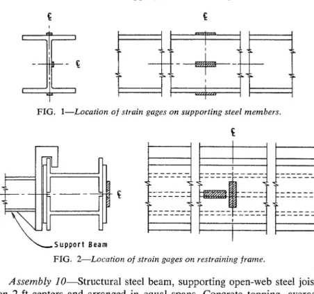
FIG. I-Location o f strain gages on supporting steel members.
L S u p p o r t B e a m I
FIG. 2-Localiorz o f strain gages or2 restrairlirlg frame.
Assembly 10-Structural steel beam, supporting open-web steel joists on 2-ft centers and arranged in equal spans. Concrete topping, average depth 3% in., placed on ribbed metal lath reinforced by wire fabric mesh. Protected by suspended membrane ceiling.
Assembly 11"A simple beam of rectangular cross section, with one end resting on a bearing plate and the other on rollers protected with
%-
in. asbestos fiber board, and the furnace opening was closed with an unattached insulating topping consisting of "/y in. of asbestos fiber board, %-in. asbestos millboard and 6 in. of rockwool approximately 3 ft wide. The intermediate support beams in each of the assemblies briefly de- scribed above (except Assembly l l ) had an effective span of approxi- mately 160 in. and were restrained against longitudinal expansion. ThePEARCE AND STANZAK ON STEEL-SUPPORTED FLOOR ASSEMBLIES 1 1
beam of Assembly 11 had an effective span of approximately 186 in. and was completely unrestrained. Strain gages were attached t o the top flange, web and bottom flange at the center of the supporting structural steel beam, oriented to record the maximum tensile and compressive strains due to bending of the beam under load.
T A B L E 2-Frunze l o a d .
Assembly No, t i i f (mas), i n , M a s I'rame Avg n e n m Tem-
Load, lb perature, deg F Time' min
1 . . . 185 1.67 155 500 1002 170 3 . . . 215 3.32 144 800 1 200 155 5 . . . 185 2 . 3 3 150 200 1032 170 6 . . . 90 2.26 98 000 1105 80 9 . . . . 215 8.90 159 000 1150 150 10 . . . 160 15.0 177 000 950 145 - S i m p l e , R o n - C o m p o s i t e , B e a m - - M E A S U R E D L I V E L O A D S T R E S S D E S I G N L l V E L O A D S T R E S S
FIG. 3-Stresses (based or1 recorded strrrir~.~) rlcseloperl dlirirlg lorld applica- tiorl, irl berrr~zs of as.serr111lic~s 2 , 5, ctrld 9.
Method of Determining Stress in Supporting Bean1
Strain gages were attached to the steel supporting members in each of the test assemblies described previously and located as illustrated by Fig. 1. T h e live load was applied in 10 per cent increments. Strain gage read- ings were recorded at each loading increment.
Method of Measuring End Thrust (Frame Load)
Strain gages were attached to the east and west sides of the restraining frame and located as illustrated by Fig. 2. T h e frames were calibrated by applying a known thrust between the two sides of the frame at the lo- cation of the suport beams with the output of the strain gages recorded
1 2 FIRE TEST METHODS
at each increment of thrust. Strain readings were recorded for the dura- tion of the fire tests of those assemblies designated as Nos. 1, 3, 5, 8, 9, and 10. The deflection and temperature of the support member were also recorded at significant intervals during the test.
Results
General
Information pertaining to the composite nature of the assernbliks is contained in Table 1. Table 2 gives information on end thrust measured during the fire tests of Assemblies 1, 3, 5, 8 , 9 , and 10. Figure 3 shows the
"
atN e u t r a l A x i s
" b
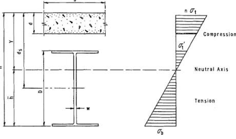
FIG. 4-Sitnple composite beam.
stresses based on strains4 which were developed during load application in the beams of Assemblies 2, 5 , and 9. The linear character of these curves indicates that at room temperature, elastic analysis may be ap- plied to the structures under consideration. (Beam strains were not measured during the fire test.) Each of these structures displays a certain degree of composite action, as indicated by the difference in the stresses measured in the upper and lower flanges of the steel beam. As used in this paper, the term "composite action" means the load sharing of the support beam and the floor it supports by virtue of the shear connection existing between these two elements of the construction. Shear strength of %-in. fusion (plug) welds used to secure steel deck section to sup- porting structural steel members varies with gage of the metal and is approximately 5000 lb for 1 6 gage deck.
PEARCE AND STANZAK ON STEEL-SUPPORTED FLOOR ASSEMBLIES 13
Calculation of Degree of Composite Action
The following is concerned with the development of an expression defining the degree of composite action present in each of the tested assemblies.
The simple composite beam model shown in Fig. 4 may be employed for the purpose of analysis. The equivalent width of the slab is taken as 1/4 in accordance with the design requirement of the current CSA Standard.5 The true effective width of concrete slab varies with the ade- quacy of the shear connection between the slab and the steel beam. The general calculation method is as follows (referring to Fig. 4):
where
Then the moment of inertia of the composite beam is:
As is seen, this calculation procedure is based on transformed concrete area.
In attempting to analyze the actual beam-floor used in the fire test (which is not normally fully composite), elastic analysis may again be conveniently employed. The distance of the lower flange of the beam from the neutral axis
(h,)
may be determined from the measured stresses by means of the relation:The moment of inertia of the beam is then obtained from the expression ME,
I = - . . .
'Jb
which, combined with Eq 3 yields
It should be noted that this method of analysis is based on the assump-
'
"Steel Structures for Buildings," CSA Standard S16-1965, Canadian Standards Assn., Ottawa, Ont., Canada.14 FIRE TEST METHODS
0 10 20 30 4 0 5 0 60
8
1
x 10' i n . / i n . FIG. Sa-Deflection curves.tion that the neutral axis of the beam is located in the web of the steel beam; it is not valid for other cases. Finally, the degree of composite action (as calculated and entered in Table 1) is given by the expression:
in which
According to this definition for degree of composite action, C = 0 when I = I, , and C = 1 when I = I t .
Effect of Composite Action upon Structural Fire Endurance
From the practical point of view, the question arising from the results of the foregoing analysis is: T o what degree does the composite nature
PEARCE AND STANZAK ON STEEL-SUPPORTED FLOOR ASSEMaLlES 15
of an assembly influence its structural fire endurance? An examination of the deflection and rate of deflectionG curves illustrated in Figs. 5a and
b, respectively, show that the simply supported noncomposite beam (No. 1 1) approached failure at an average temperature of 11 85 F, a beam with a very low degree of composite action (No. 2) approached failure at a n
F I G . 56-Rote of deflection.
average temperature of 1270 F, and a fully composite beam (No. 7) had not approached failure at an average temperature of 1600 F.
In order that fire tests might be terminated prior to, but reasonably close to ultimate collapse, Robertson and Ryan ("Proposed Criteria for Defining Load Failure of Beams, Floors, and Roof Constructions During Fire Test," Jolcrtznl of Reseorch, National Bureau Standards, 63C, 1959, pp. 121-124) proposed that the point at which both 6 = 12/800 r l and b' = ['/I50 d can be regarded as an indica- tion of load failure. In these expressions 6 = maximum deflection, in. 6' = rate of deflection, in./hr, 1 = clear span of principal structural element, in., d = distance between the upper and lower extreme fibers of the principal structural element, in. These values have been marked by arrows in Fig. 6 to give a n indication of the structural condition of the assembly at the time the test was terminated.
16 FIRE TEST METHODS
The fire test on the simple noncomposite beam, as well as more basic consideration^,^ indicate that such members will become incapable of supporting their design loads at temperatures between 1100 and 1200 F. Review of the fire test results show that the degree of composite action existing in an assembly has the effect of prolonging the structural fire endurance period beyond that of a simple noncomposite beam, by an amount which is proportional to the degree of composite action.
Variation in the behavior of individual assemblies-(for example, in the case of Assemblies 3 and 9, the former showed no sign of rapid de- flection at an average beam temperature of 1400 F, while the latter was approaching failure at the same temperature, although it had the greater
0 100,000 200.000 A P P A R E N T F R A M E L O A D . L B S
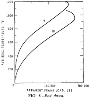
FIG. 6-End thrust.
degree of composite action) may be explained by a difference in the shear forces resulting from the applied load experienced during the fire test. (The live load on the beam in Assembly 9 was 1.73 times that on Assembly 3, although the strength of the welds was approximately the same in each case.) During the course of the fire test there is an audible indication of the failure of shear connections between the steel deck and the suport beam. On assemblies where this has been observed, there is a marked increase in deflection rate after failure of the shear connec- tions has been initiated. This indicates that significant reduction of the degree of composite action precipitates load failure for this type of as- sembly.
PEARCE AND STANZAK ON STEEL-SUPPORTED FLOOR ASSEMBLIES 17
Relationship of Applied Restraint and Degree of Composite Action and Their Combined Effect on Fire Endurance of an Assembly
Turning now to the question of restraint, Fig. 6 compares frame load (as obtained from the strain measurements) with average beam tem- perature for Assemblies 9 and 10 which incorporated steel beams of almost equal cross-sectional area. It is interesting to note that the maxi- mum reaction was almost the same for both assemblies, but in the case of No. 9 the maximum point occurred at a much higher average beam temperature. This development is thought to result from the difference in degree of composite action inherent in these two assemblies. Tests at the Ohio State University8 indicate that there is an "optimum" degree of external restraint which can be applied. The fact that development of composite action between the beam and the floor reduces the magnitude of applied restraint at a given beam temperature may have the effect of optimizing the restraint of the steel beam.
The important practical effect of the applied or external restraint is to preserve the shear connection between the floor and the support beam-and, hence, the composite action. Therefore, the degree of com- posite action and applied restraint are factors which complement each other and, acting together, have the result of notably increasing the fire endurance of an assembly beyond that of a simple, noncomposite beam.
Conclusions
A review of the test data developed from the representative assemblies described in this paper indicates that the actual live load stresses devel- oped in the steel support beams of such assemblies may be expected to be below the design working stresses to a degree which varies greatly from one assembly to another. In addition, the development of a varying degree of applied restraint against thermal expansion to both the steel beam and the concrete during the fire test has tended to obscure the significance of the st:uctural behavior of these assemblies.
It is suggested that the existing standard might be modified to advan- tage by requiring more representative loading to assemblies propor- tioned by elastic design methods, thus re-establishing the intent of the original standard. With assemblies loaded in such a manner as to de- velop in each member the actual stresses contemplated by the design, there would be greater justification for a wider application of the data derived from such tests.
18 FIRE TEST METHODS
DISCUSSION
I . A . Ber7jamiiz1 (written discussion)-The authors are to be com- mended on having taken the time and effort over many years to compile actual stress and strain data on steel beams from test constructions.
The data which they have tabulated indicated quite clearly that over a fairly wide range of steel beam floor constructions, composite action is developed regardless of the theoretical stress calculations. Although the beams shown in Table 1 are presumed to have all been initially stressed to a calculated dead and live load stress of 20,000 psi, the highest stress measured in any floor construction consisting of steel deck and rein- forced concrete was 15,600 psi or 78 per cent of the theoretical value.
T h e authors feel that the degree of composite action affects the critical temperature and rate of deflection of the beam, as they have shown graphically in Figs. 5a and b. They point out that the simply supported noncomposite beam No. 1 1 approached failure at an average tempera- ture of 1130 F. However, this beam is not a "simply supported" beam in terms of structural design concept; but is a roller-supported beam- atypical for design considerations. The effective difference in restraint between roller supports and standard end connections has been markedly brought out in Professor Bletzacker's paper.2
As indicated in Professor Bletzacker's paper, roller-supported beams with no end restraint, having a range of measured fiber stresses from 16,900 to 22,000 psi, all failed within a few minutes of each other. This would indicate that the stress on the bottom fiber is not the only critical condition when the beam is on a theoretical roller-supported condition.
The authors' data would indicate that the stress in the extreme fiber does not tell the whole story, even for restrained beams. For example, beams No. 3 and 7 are both approximately 25 Ib/ft sections. Although one has twice the stress in the bottom flange of the other and a range of composite action from 0.26 to 1.0, they exhibited similar performance. Of considerable interest in the authors' paper is the observation that all the floor sections tested, conlposed of steel deck with concrete placed on top, showed average temperatures in excess of 1200 F before reaching limiting rates of deflection.
Although the data are not complete, we might infer from Figs. 5a and
b that the critical factor is not the stress in the section but the amount of heat sink on top of the beam flange. The bar joist type of constructions, which are most sensitive to temperature, do not have the concrete slab
: Director of research, Granco Steel Products Co., St. Louis, Mo,
DISCUSSION O N STEEL-SUPPORTED FLOOR ASSEMBLIES 19
resting directly on the beam flange. T h e difference in performance be- tween Test 2, the bar joist construction, and Tests 3, 7, and 9, which have the slab in contact with the top of the bcam flange, could well be attributed to the difference in heat sink.
Figure 6 shows that the average end thrust occurs at a lower tem- perature for the bar joist than for the steel deck floor construction. This situation is consistent with the concept that a better heat sink will pro- vide a greater differential between top and bottom flange, therefore allow- ing a higher temperature to occur in the steel before the maximum thrust is reached. T h e graph does not necessarily prove that the temperature difference at maximum restraint is the result of a variation in degree of composite action.
I n summary, I agree with the authors' statement that the actual stresses developed in a typical floor construction are :css than the theoretical de- sign stresses-this is the nature of the design assumptions which are used. Any other loading requirement woulcl be a forced condition and, particularly on certain types of reinforced concrete constructions, would require loading above design load to crack the concrete in order to de- velop the design stress in reinforcing bars.
The degree of restraint and the amount of heat sink directly in contact with the top flange of the beam may be the governing factors in beam performance.
N. S. Pearce and W . W. Stanznk (authors' c1osrlre)-The authors wish to thank Mr. Benjamin for his interest in their paper.
Mr. Benjamin has commented upon the data included in Figs. 5n arid b which were included in the paper to illustrate the difference in pcr- forrnance exhibited by assemblies having varying degrees of compositc action. From further review of the data, the authors would be most reluctant to conclude that the difference in the heat sink afforded by the assembly of bar joist construction, Assembly 2, contributed in a more significant way to performance of the assembly than did the difference in degree of compositc action. T h e authors would refer to Harrnathy's paper:; which clearly shows that the creep resistance of a beam at an aver- age temperature of, say, 1600 F is so small that the beam would have difficulty in supporting its own weight. Therefore, in assemblies such as No. 7, as the result of composite action, it is conceivable that no appre- ciable bending stress was present in the support beam during the ad- vanced stages of the fire test. As the average bcam temperatures plotted in Figs. 50 and 1) included upper flange thcrrnocouple readings, the heat sink cflect does not necessarily explain the difference in structural per- formance of the various assemblies, although the relative coolness of upper beam flange and the floor deck is most necessary in preserving the compositc nature of the assembly.
20 FIRE TEST M E T H O D S
With reference to Fig. 6,.the authors agree that the greater tempera- ture differential between the upper and lower portions of the beam might, in part, explain the temperature difference between the points of maxi- mum thrust. The authors intend to pursue this point in their future in- vestigations.
E. G. Butcher4 (written discussion)-The authors of this most inter- esting paper make the comment that the development of a varying degree of applied restraint against thermal expansion has tended to obscure the significance of the composite assemblies tested. T h e importance of this factor is now becoming generally realized and is probably one of the causes of variation in fire test results. T h e measured values of the end restraint which obtained in two of the tests reported in this paper indi- cate that these forces are considerable (up to 180,000 Ib) (Fig. 6 and Table 2).
T h e authors ascribe the difference in the end thrust shown by the two curves of Fig. 6 as being due to the difference in degree of composite action inherent in the two assemblies. But is it not possible that small differences in the assembling into the test frame could have produced the same effect? T h e difference between the two curves in the 0 to 2 0 0 F region would seem to indicate that this might have been the case.
In discussing the effect of composite action upon the fire endurance, the authors make the point that a simply supported noncomposite beam approached failure at 1185 F (640 C), a beam with a small amount of composite action failed at 1270 F (680 C), but a fully composite beam had not approached failure at 1600 F (870 C). It is not clear, however, whether these results are due to any difference in the fire behavior of the composite beam o r whether they are due to the fact that the loads used developed lower stresses in the composite beams than in the simple beam. Figure 3 and Table 1 would seem to indicate the latter.
N .
S.
Pearce and W. W. Stanzak (author's closure)-The authors also wish t o thank Mr. Butcher for his interest. We would agree that a varia- tion in the end thrust shown by the initial portion of the two curves of Fig. 6 could be produced by small differences in the method of assembly into the test frame. However, after reviewing the test data and recalling the care with which the structural steel beam supporting members were placed into the restraining frame, we would prefer to remain with the observations contained in the paper. A s to the effect of composite action upon the fire endurance period, it was the intention of the authors to attribute the variation of fire endurance between assemblies incorporating support beams having no composite action, a small amount of composite action and fully composite action, t o the variation in the initial stresses resulting from each assembly having been loaded as though the beams were simply supported."oint Fire Research Organization, Fire Research Station, Boreharn Wood, Herts, England.