COMPUTER-AIDED INDUSTRIAL PROCESS DESIGN The ASPEN Project
First Annual Report for the period
June 1, 1976 to May 30, 1977
Energy Laboratory
Report No. MIT-EL 77-013
June 15, 1977
Energy Laboratory Report Number MIT-EL 77-013
MIT-2295T9-4
Dist. Category UC-90
COMPUTER-AIDED INDUSTRIAL PROCESS DESIGN
The ASPEN Project
First Annual Report
for the period
June 1, 1976 to May 30, 1977
Department of Chemical Engineering and
Energy Laboratory
.Massachusetts Institute of Technology
Cambridge, Massachusetts 02139
Date Submitted: June 15, 1977
PREPARED FOR THE UNITED STATES
ENERGY RESEARCH AND DEVELOPMENT ADMINISTRATION
.FOSSIL ENERGY PROGRAM
This report was prepared as an account of work sponsored by the United States Government. Neither the United States, nor the United States ERDA, nor any of their employees, nor
any of their contractors, subcontractors, or their employees, makes any warranty, express or implied, or assumes any legal
liability or responsibility for the accuracy, completeness, or usefulness of any information, apparatus, product, or process disclosed, or represents that its use would not
infringe privately owned rights.
Printed in the United States of America Available from
National Technical Information Service U.S. Department of Commerce
5285 Port Royal Road Springfield, VA 22161
The following members of the Project staff contributed to this report: Mr. A. Armar Mr. C-C Chien Professor L. B. Evans Dr. P. W. Gallier Mr. E. Garcia-Gamboa Mr. R. Gautam Dr. B. Joseph Mr. P. K. Mun Mr. J. Neville Dr. E. Ng Mr. J. N. Peterson Professor W. D. Seider Mr. S. Tia Mr. G. L. White
TABLE OF CONTENTS
Page
ABSTRACT
I. OBJECTIVE AND SCOPE OF WORK 2
II. SUMMARY OF PROGRESS TO DATE 4
List of Publications Issued
Under this Contract 4
Task Summaries 5
Program Schedule 11
III. DETAILED DESCRIPTION OF TECHNICAL PROGRESS 19 Task 1. Development of a Prototype Simulator and
Simulation of Specific Fossil Energy
Processes 19
Task 2. Development of ASPEN System Structure 50 Task 3. Development of-Physical Property
Subsystem and Data Bank 63
Task 4. Development of Unit Operations Subsystem 82 Task 5. Development of Cost Estimation and
Economic Evaluation Subsystem 83 Task 6. Development of Data Regression Subsystem 86
Task 7. Acquisition of Proprietary Software
and Modification for Use in ASPEN 87 Task 8. Integration, Testing and Documentation
of ASPEN System 95
IV. CONCLUSIONS 96
APPENDIX A. Description of PLEXSYS II Physical
ABSTRACT
Work during the first year of this contract concentrated on acquiring the project staff, development of a prototype
simulator, the simulation of three coal conversion processes, a survey of software for acquisition, the development of a preliminary physical property subsystem, and the setting up of an advisory committee consisting of industrial government
and university representatives. The prototype simulator, PLEXSYS II has been completed and is now being used in the
simulation of the IGT HYGAS process, the Conoco CO2 Acceptor
process and the Exxon Donor Solvent process. Simulations of the HYGAS process and the CO2 Acceptor process will be
completed in August, 1977. Negotiations are under way with Exxon to release the proprietary data necessary to complete the simulation of the Donor Solvent process. The preliminary physical property subsystem incorporating properties of coal is being used in conducting these simulation studies. The
software survey has been completed. The programs surveyed are now being evaluated for possible acquisitions. Negotia-tions will be conducted with holders of proprietary software for release of their programs to the ASPEN project. An
advisory committee, consisting of representatives from 28 companies, 8 universities and 6 government laboratories has been formed to aid in the design of the system.
I. OBJECTIVE AND SCOPE OF WORK
The objective of this project is to develop a computer based process simulator and economic evaluation system for use in the engineering of fossil energy conversion processes. The system has been named ASPEN (Advanced System for Process Engineering). It will provide the U.S. Energy Research and Development Administration (ERDA) with a rapid, efficient, and consistent means of performing its process evaluation functions.
For a process such as coal gasification or liquefaction, ASPEN will be capable of performing detailed material and
energy balances, equipment sizing, and economic evaluation. It will be designed to meet the specialized requirements of. fossil energy conversion processes, including an extensive data base for coal physical properties, compatibility with conversion reactor models currently available and/or being constructed, and the capability of handling streams of solids.
The scope and specific objectives of the project are to: 1. Develop a prototype simulator and demonstrate the
ability to simulate three specific fossil fuel conver-sion processes of interest to ERDA (HYGAS, Donor Solvent, and CO2 Acceptor).
2. Develop a system structure of ASPEN with the necessary flexibility to model the different process configura-tions encountered in fossil energy process development
and to allow insertion of proprietary programs and data for use by industry
3. Develop a physical property subsystem that will cal-culate the properties important in modeling fossil energy processes. It will have an associated data base for coal physical properties.
4. Develop a unit operations subsystem which will have
process models for all major types of equipment used in fossil fuel conversion processes.
5. Develop a cost estimation and economic evaluation
subsystem that will compute capital investment,
oper-ating costs, and profitability of proposed designs. 6. Develop a data regression subsystem that will utilize
experimental data to compute coefficients in
correla-tions for physical properties.
7. Acquire existing industrial programs and data and
modify them for incorporation into ASPEN. This will
avoid the need to redevelop existing, standard routines for modeling unit operations, physical properties,
and other calculations.
8. Demonstrate the capabilities of ASPEN by simulating a
II. SUMMARY OF PROGRESS TO DATE
The work under Contract No. E(49-18)-2295 Task No. 9 is organized into eight reporting tasks. Summaries of work accomplished in these tasks appear in this section, for the period June 1, 1976 to May 31, 1977.
The year's work has resulted in the publication and/or presentation of the following reports, theses etc.:
Evans, L. B., B. Joseph, and W. D. Seider,
"Computer-Aided Industrial Process Simulation and Design." Paper presented at the Conference on Mathematical Modeling of Coal Conversion Processes, Washington, D.C.,
November 1976. Available in Report No. CONF-761104, Energy Research and Development Adminstration,
Wash-ington, D.C.
Evans, L. B., B. Joseph, W. D. Seider, "System Structures for Process Simulation," accepted for publication in the
AlChE Journal.
Evans, L. B., W. D. Seider, "The Requirements of an Advanced Computing System for Chemical Process Engineering,"
Chemical Engineering Progress, 72, 6 (1976).
Joseph, B., L. B. Evans and W. D. Seider, "The Use of a Plex Data Structure in Process Simulation," submitted for publication to Computers and Chemical Engineering, Per-gammon Press. Also presented at the National Meeting of the AlChE, Kansas City, Missouri, April 1976.
Peterson, J. N., "Survey of Software for Computer-Aided Chemical Process Design," M.S. Thesis, Department of Chemical Engineering, Massachusetts Institute of Technology, January 1977.
Seider, W. D., B. Joseph, E. G. Wong, and L. B. Evans, "Routing of Calculations in Process Simulation,"
Paper presented at the 69th Annual Meeting of the AiChE, Chicago, Illinois, November 1976.
Wong, E. G., "Routing of Estimation Methods for Calculation of Physical Properties." M.S. Thesis, Department of Chemical Engineering, Massachusetts Institute of Tech-nology, June 1976.
The following are task-by-task summaries of progress during the past year.
TASK 1, DEVELOPMENT OF PROTOTYPE COMPUTER SIMULATOR AND
SIMULATION OF SPECIFIC FOSSIL ENERGY PROCESSES
During the past year the prototype simulator, PLEXSYS II, was programmed and is now in operation. The plex structure has proved to be a very flexible arrangement for modeling
the different types of unit operations present in coal con-version operations. Preliminary experiments showed that the
extra computing effort required to store and access informa-tion from the plex is not excessive. The prototype has
demonstrated the use of plex structure in FORTRAN as an alternative to fixed array storage.
Simulation of the HYGAS coal gasification process is now being completed. All the unit modules required to complete the simulation have been prepared. These include two alternate models for the gasification reactor and the methanation reactor. A program prepared by the University of West Virginia has been adopted for sizing the acid gas removal section of the plant.
Modeling of the Exxon Donor-Solvent process has begun. Progress has been hampered by the lack of published litera-ture on the process and restrictions on access to Exxon's proprietary data. A meeting was held between Exxon, ERDA and MIT representatives in May to discuss the release of
proprietary information to MIT. Negotiations are currently underway with Exxon to release some of the proprietary data
on the process under a secrecy agreement.
The simulation of the C02-Acceptor process is also scheduled for completion during the next quarter using a combination of PLEXSYS II and FLOWTRAN. Contacts with the Conoco Coal Development Company were made to obtain pilot plant data and programs developed by Conoco to model the process. The simulation of the process is being carried out in two stages. The preliminary section of the plant involving solids handling such as crushing and grinding will be modeled using PLEXSYS II whereas the gas clean up operations will be simulated in FLOWTRAN. By combining the two simulators we can overcome the deficiency of FLOWTRAN in dealing with solids. Programs for gasification and dolomite regeneration were obtained from Conoco and are being converted for use with PLEXSYS II simulation.
TASK 2, DEVELOPMENT OF ASPEN SYSTEM STRUCTURE
An advisory committee consisting of representatives of industry, government, and universities was formed to guide development of ASPEN and to insure that it will meet the needs of the ultimate users.
A list of preliminary design criteria for ASPEN has been prepared. A questionnaire based on the criteria is being sent out to all members of the Advisory Committee to
get feedback from the industry users of computer software. During the next quarter, a list of functional specifications of the systems will be drawn up based on the results of the survey. A meeting of the Users/Use Interface Subcommittee of the Task Force on System Design will be held in August. Negotiations are underway with a software company, SOFTECH, to obtain assistance in the design of the system.
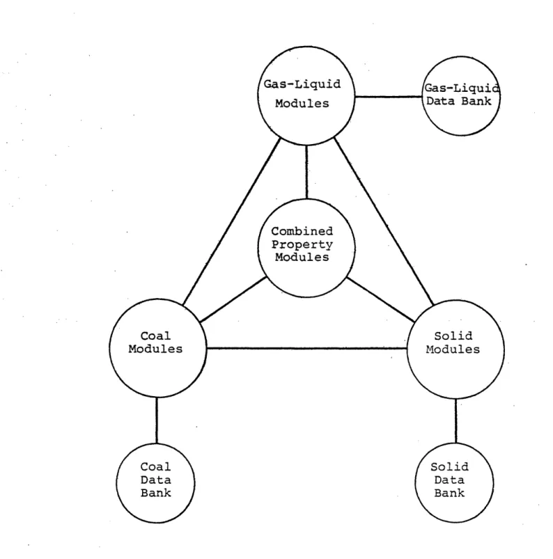
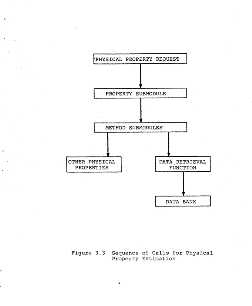
TASK 3, DEVELOPMENT OF PHYSICAL PROPERTY SUBSYSTEM AND DATA BANK
During the past year, a preliminary version of the physical property subsystem was developed. In addition, methods for calculating phase and chemical equilibrium were investigated under a subcontract with the University of Pennsylvania.
The preliminary physical property subsystem (PPS), designed for PLEXSYS II, is being used in the simulation of three coal conversion processes. The PPS incorporates ideas of routing and modularity which are needed in ASPEN. Programs for simulating properties of coal are included. Modules for calculating properties of gases, liquids and coal have been implemented. A report on the physical property system is being prepared and will be submitted separately to ERDA along with this stand alone PPS. All programs in the system were tested against experimental data available in the literature or when experimental data was not available,
The coal properties estimation modules incorporated in this PPS are based on the Coal Conversion Systems Tech-nical Data Book being prepared by IGT.
Under the subcontract, different methods for calculating phase and chemical equilibria were surveyed. Better implemen-tation of existing methods and new methods were investigated. A number of example problems were selected from literature to study the effectiveness of this technique.
TASK 4, DEVELOPMENT OF UNIT OPERATIONS SUBSYSTEM
A list of unit operations modules required by ASPEN has been assembled and complete descriptions of the data required to specify them, methods of calculation, etc. are being prepared. The list will form the basis for deciding which modules need to be acquired, which programmed in house, and which are not essential to ASPEN. Work on this task is not scheduled to begin until the second year.
TASK 5, DEVELOPMENT OF COST ESTIMATION AND ECONOMIC EVALUATION SUBSYSTEM
The existing cost estimation and economic evaluation programs are being analyzed to better define the capabilities required in ASPEN. Among those being analyzed are ECONOMIST, PROVES, CHEEP, PEPCOST and CEDA. However, work on this task is not scheduled to begin until the second year.
TASK 6, DEVELOPMENT OF DATA REGRESSION SUBSYSTEM
Work on this task is not scheduled to begin until the second year.
TASK 7, ACQUISITION OF PROPRIETARY SOFTWARE AND MODIFICATION FOR USE IN ASPEN
Acquisition of software has proceeded on two parallel paths. The first subtask was to acquire a base simulator which will provide basic capabilities for simulating vapor -liquid processes. Programs of potential interest to ASPEN were identified. Negotiations are currently underway to acquire a simulator which will provide ASPEN with the
capability to do simulations of processes involving vapor -liquid streams. This will assure that ASPEN will be built on current technology and will not duplicate work that has already been accomplished by private industry. The base
simulator will also provide ERDA and its contractors with an immediate tool which can be used to simulate parts of
energy conversion processes involving only liquids and gases. The second subtask was concerned with identifying
software which may provide modules to be incorporated into the integrated ASPEN system. An extensive survey of industry, universities and commercial software houses was conducted
to identify programs that were of potential use to ASPEN. More than 500 letters were sent out. About 210 returns
have been processed so far and over 440 commercial, university and proprietary programs were identified. A meeting of the Task Force on Software Evaluation was held
at M.I.T. on May 2 and 3, 1977 to screen out programs of inferior quality or programs that were irrelevant to the project. The project staff is currently evaluating the programs that were screened to better identify their scope and capabilities. The programs have been divided into five categories to aid in the evaluations, namely: heat ex-changers and reactors, separation processes, physical prop-erties, cost estimation and economic evaluation programs and miscellaneous unit operations including mathematical routines.
TASK 8, INTEGRATION, TESTING, AND DOCUMENTATION OF ASPEN SYSTEM
Work on this task is not scheduled to begin until the second year.
Program schedules for the eight reporting tasks appear in the pages directly following.
0~- ii..lI -- >1 4-) 0 .-H aO n C a) 1 CO p m
c, 4 -.
a-0 a-0 . H a 00 a ) S Cda C)a a, a) O aU)C) (3) U) o a) l) 3 4) CO a) O a) .H a) , 1O O 0 0 Co3 O 4i O Q O O 4J 03 .O CO , o H 3 ro 0 4-4 -iJ > Q · a) a) O C c, Cd O a) 0 *H O H o q a) o Eq r Cd Hrq UO -Pr 0 04 a) z a) (d 04 a P4 0 < N m V Ln Ut _ a'a_ H-id C H r-4 co, a) t~ r- 4 Ol - '- H--I C W r4 l U r-4 n p .w to ·ro (3;M
P4i U) E- O UN P; C L4 W E-i O . EjH O40
E Z Z W OzH
H CnU r-I H 0 z CU] I I _ _ ___ U__0 -H: . U) 4to E) to V·W X W o 043) z -i- - 0 .- H-H-H-·4 0 WM 01 0 d ot t 01 o- -HM O-4 O O->1 -I U >1 04 U -H )
P oaUom u:
H *-H H 44 > ci) >d %H -H, i Hz o) 0 f 0) > Q) 4 4 3-H 4. 34 ) 03Ur)0) P H04 04-H (a -H -H -H > 0 > 4 U) U) H' L m I'l r 0o OOz
H U) W m Un t l -.4 k 0 4onO O cU 4 ) 0-H V r(-H cr 0 O 4O V ~ I H Q- 0 . . -H 4 43 0 - - U c0. 0 l 0 4 .- OO 4H H 0 ) a) U) ZW C 04Q Uo
0) -H 0 8 .H VU >, -H 4-4 0a . -H cI -H > 04 ~.4 tP I la 4- a 4 .3 )-Z O0 H Ez Z H r-4 N v ' oD - mr
H -ir- ---I , - r-- r!, . Z r V> -H-H 4.3) OO oU -H 4 0 '4000.
·
0-ax~4U) U-) U)J O ) >1 O NO (C) E Eq r O44 WM) H 4 · r , O ~.O Q S- 4c a) ) z ) a) ro o 4.) A U U H oa
O7 en) C14 Hl ro r, r4J ka'
rI H y _ _Io, r-i-i ,4 tn -v-I0
W AQ P:0
. A u Ca pq W4 E-1 U U) r:z
z
3
0
z
v
H U) H ,2 H (NI 0z
Encu E -(1~~~~~~~1()Q
~ ~ ~
<<<<<<<,
rt 0 , a U) 4d U -r ) U) C l >1 0 rd rl4U)t H O vl C C m U -H 0 a) 4-1 U
-
*ii
*t
0.
0C
N \ 4 04 PI * 4) £ H rI( 0 4 a44 0) : a) 4 C )v Ln 'O r-c~t rM M --4 4- U) a) m E-4 0) *H O.) :~
E4 U)0
co U) 0 *r Uq t U) CQ o ) dr. w r r E- 440
N4
d N -H -H a) 0o ZD 4 o U00 O * * H H H H (Pt) ,I-a Ir, cD r-3
o3
u, -i 3 > AP m 0z
U) En 4c c> a) 0 Cd -l H U)H lU) *H 0 14W *H U PCi) U)Q(1) :: 1=1m! Z E-4 U] U H ul U<U] o 0 4-4d · 4..) a) U) 0 0 · *H 4 -* o H H t; 4 c4 r-) P m U ) 0 l4 a74 (0 0- 5i .U i 3 ·k t 04
H4
04 J4 0 a 0a C N14 O 0 0 04 4. ) >a z
a) ) ro 01 C3 H E-1 U] U) E H P LO ,o *r4 0 4 4.) a) (a. En E IL) rd a) fl O t 44 A *,r-o a) 01 d · · 0 01 H · C4 5-4 0 O O U) U 44 ) . U r- Oi Ha
ra
g-U %D UcroU
0 , 0 > P4 U)' U] U] U) H Ea H Z0
H 0P0
0q H w E-4 rn U) U ..H v 0:z
a) U) m a)(U) Cd
a
I U)o ~ :l ) l f.o - H *H *H 0'N r ro 0 00 0 E~ E-rfj P.. Eq0
CN m ll n y> F- CO U)*
ro
G a o m a= 0 44 tH a) a1 t ) ) W 0a U) Cd O 0 N - L O H H H H H F-", oC r-rl 1" O~ WUD
U U to rd > O 9 P ;z
OH H 1 P P H P m E-4 Z ul O H O P . ,j ZX H O ,-]O>O
mr w r) -P U) a) ·H 4-)0a))
cO0 O ---r M Cr-
a
4JH Cd U) 44 kCQ4 u 0 O rd o wP U . ro m )a U)0 o HCd
I z w E O nz
Lt HU]a) E E-1 *, u *,i U) -HW 4 Q 4-) rn > O o m ·
*
E ) -U a Q y * a * $ ) r- a Q 0 r1 r u4-) a 0 r U) M EH Cl W E-H CN m LO0
.r U U) *H a) 4 -'H U) rd
r
a) 0 '.01
0 0 U) 4 to ( a) > 54 4 04 U '.o r- coa
r, I-a a 1, U ,4 A ru ;
Pi D0
H rz 0z
o
E3 6 z Da %O E-4 > o Vl U b; HEn 4.) co >·1 U) 03 0 O -d 5 O C1 · Cd i 0 0 )
~0
,.--! o3 ] 3 1 O .:1 4) Md- U) )n 4-4 r.3 --E · , h ·r-I C f>~~~
0 ~ ~O Cd 0 --~ 0~~~
- ~40 54~ U) En )r~
4) C 03~4 n 40 H~ E -iw CdE4U) U) *H U)4)4J 5-i 0 mCd rz
U) U) E-4 .4- 3 -H 5 d C(d r-4 * U) Cd 0 H -rH r-l X P N 5 Cd 434- Cd CO- 04 z- U)
~')
>4U -H k U) ~ U) U) 0' U) H 3HZH > C.) U) U) r> 5-4 0 -ii -i U o * * 3 5- Cd C) 5-IQ: CdUQ 0 ) 04 U U) 04 N m F-- L I9 9 9
9
Ni 14· 0 c P 4-) Cd C= .4J 4-) CC4 a) 0 C4 ~4 0) C 5-4 04 0 =3 0 ·. o, tr .U a (d H 0 d a) z rl > 4.) C L Cd 0 -* -i U) 0orX4 z
z
N- 00 m N N rli 0, 0, a~ W :3 r-W r4ro
(D ! wr Or) rz §WO~
E- P4 Z m· H 04O P1Z O r~H EZu OH Hr 04 0 HE-C/O H E-1 H m N Cz
U)U Ce d0 4J m >1 .>1 o3 D o 4J 0)3 ( a a 43 ad Ce C a) a) H . P-I PI cl H (N (n "- L r3 C) a) E-1 H 4 U) H -i W W
(a·
o Ha
O z p(. ) H >1 () g~ ~ 0 J z : U) 0 )aa O ) 0) $4 0) ) tn C 43 43 43 Ca 0) Ce 0) ro r IT 0) > r U 0 a 0 04 4 ) a) C H (N m N oD 0 H H H H H r,,I-r
c ImDr
D r-Ca O > U 3 O l ,i -.i n EH 0 4I ZC U) ZH z n OH 3 H ZO E-Z H O E E U Z O H a a) r.4 Cd Ca E a) Hn-l O (~ 0 0-4 5 C a zS 0z
Cl H C W E-1 >4 trn U HIII. DETAILED DESCRIPTION OF TECHNICAL PROGRESS
TASK 1, DEVELOPMENT OF PROTOTYPE SIMULATOR AND SIMULATION
OF SPECIFIC FOSSIL ENERGY PROCESSES
One of the major tasks for the first year of the project was the development of a prototype process simulator to test new concepts in process simulation needed to model fossil energy processes. The prototype simulator, named PLEXSYS II, is being used to simulate three coal conversion processes: The IGT HYGAS Process, the Exxon Donor-Solvent Process, and the Conoco Coal Development Corporation C02-Acceptor Process.
1.1 DEVELOPMENT OF PLEXSYS II
The basic system programs for PLEXSYS II were developed for and implemented during the second quarter of the project. The unique aspect of PLEXSYS II is the use of a plex data structure to store information regarding a process.
In current simulators, data are stored in fixed arrays, usually residing in common in FORTRAN programs. This struc-ture leads to inflexibility, because the designer of the system must know all variables of interest at the time the system is designed. It becomes difficult to incorporate new types of variables without altering the layout of data in COMMON and changing every routine that was defined on the basis of the original layout.
In a plex structure, first proposed by Ross (1961), information is stored in blocks of contiguous storage
locations known as beads. Beads of any length are created dynamically from a pool of free storage as needed during execution of the program. They are referenced and linked together by means of pointers. Beads may contain integer values, real values, Boolean values, character strings, and pointers intermixed as needed to describe an element of the model.
A paper has been prepared by Evans, et al. (1976) describing the use of a plex data structure for process
simulation. It was included in the First Quarterly Progress Report.
A major question regarding the plex data structure is whether the extra computing effort required to store and access information in the plex will be excessive. To
answer the question the first version of PLEXSYS (referred to as PLEXSYS I) was developed. It implemented the plex data structure with the FORTRAN programming language. A comparison was made on two example processes to compare
the effectiveness of the plex data structure with traditional fixed-array structures. The results of these studies are described in a paper by Joseph et al. (1976) which was also included in the First Quarterly Report.
For a typical process involving a flash and recycle, there was a 20% increase in execution time. However this is not a serious limitation considering the flexibility offered by the data structure. It is possible to use a combination of the traditional fixed array data structure with the plex structure retaining the advantages of both. These and other possible data structures will be explored in the design of ASPEN. The use of plex data structure makes it easier to develop modular programs that are
reusable and can be adopted to solve new types of problems. The plex structure also permits easy specification of the routes of computations when building block routines call upon other routines and choices exist at each level. Only a single argument is required when calling routines. This is discussed in greater detail in a paper by Seider et al.
(1976) which is included in the First Quarterly Progress Report. These ideas have been implemented in PLEXSYS II.
While PLEXSYS I was excellent for determining the computing efficiency of alternate data structures and the effort required to interface programs with the plex, it is of limited use for process simulations. The limitations result from a very limited set of available physical properties and limited capabilities for data management.
The second version of the simulator, referred to as PLEXSYS II, is being used for the prototype simulation of
the three fossil energy processes.
PLEXSYS II consists of two major parts: (1) The Plex Data Management System (PDMS) and (2) the Generalized Plex Building Routine (BUILD) for building a plex data structure
from free-format commands on data cards. An associated set
of physical property routines has also been developed and
is discussed separately under Task 3.
Details of PLEXSYS II are discussed in two working reports of the project: PLEXSYS II User's Manual and
PLEXSYS II System Manual.
The unit operations blocks required for the simulation of the coal conversion processes are being developed as they
are needed. The system is being constantly modified to meet the new requirements as these pilot plant simulations proceed.
1.2 SIMULATION OF THE HYGAS PROCESS
The HYGAS coal gasification process developed by the Institute of Gas Technology (IGT) was the first of the three processes selected for study using PLEXSYS II. A
pilot plant of the process has been constructed and operated by IGT. The objective of this study is to demonstrate the
feasibility of computer simulation of the coal conversion processes by comparing the simulation results with pilot plant data.
Figure 1.1 shows a schematic of the IGT pilot plant.
There are many variations to the process. -The one selected
for study is the steam - oxygen process for which operating
data has been reported by IGT. Figure 1.2 shows the major
reactions taking place in the process. Figure 1.3 shows
the block flow diagram showing the major computational
blocks, the streams and stream classes involved in the process. There are eleven different classes of streams in the process, each one distinguished by the components and phases present. The components in each stream class are
listed in Table 1.1.
In addition to specifying the stream class, it is also necessary to specify the stream type. In the HYGAS process there are six types of streams (liquid, solid, vapor,
solid/liquid, and liquid/vapor). The type of each stream is indicated in Figure 1.1. The variables required to represent each type of stream are listed in Table 1.2.
Work during the past year has concentrated on modeling and programming the blocks required to do the simulation. A brief description of the blocks that have been completed is
given below:
HTR - Block to simulate the high temperature reactor. Two different programs were written to model this block. The
rn + N 0 0 N c .) 4J 0 V--0o V--0o P4 P-4 C) U C (/2 I >01
o
An 0 C) U) . .n tn tv a) Cd l .r4 0) -4 P4 En to 0n-V 0 cn j< (1 >4 u440
rz (13 "4tp O Sr40
0 *r44-) Cd0) C) 4 .-4 01) '.4 .-H rX4 r-4 r40
0 rZl 0 -, to r-4 U) 21 .4I "4 0) 5 0 C.) M C: 0 Ct) "-4 r4 -re(d a) U) 0)
+
u
o N + + + + * * 0 U 0 + +0000
. U "-V4 -r 0 :0
:
CN '-4 a1) t-' .1-PT4 4i E Ce w P4 ~4Coal
I \- (3) (3) (3) (1) (1) (1) (2)V H20 (6)G Air -.(9)G H20 - I
o
0
0
0
Z z: = r 0 U E)c0
0
U) U ) 3 0 0 E- P Z 3 0 H , N044
4- 4. -d N NS 4-4 H 0 H o C 0 Cr1 0~ 0 E r H (4 C' IR rC f.. Z 0 00 0 0C O c 4 O Nz u
0
ro 0 N (1) 0 0 ,c: 0N >1N N H .V-1 crl k U)r4 k w 0 ,-i r> mz
0
c
IV (N,-0
0
O CN O V Z 4) I W Vn k 0 0 0~'4)
0 o( m d a) c m s:: ( t E m r U *H 0 0 C 0 0 : 4 o- m 44 N 0 -r p0 rm4. rl
I
'0 0
X R E-H Ez 3 U) A z o0 N O 0 o 0 o, O ) Cd 0 .4 H W > : Z1 z Z wrW H w13 Z EH 4 44 a) U *c c 0 H H-4 H-i U) U) 0 0 co PI ,r:n4 4 ,-I 0 c: cn1 U 0r O 00 U0f 0 44I 0 OU 0 crd Z Ua p IE4 04 Cz4 Et 0 .'l w E w 4 Xi W n Er: o o g z P~~~ 4 rZ4 4 El4 0. 94 El4 2: E4 co 03 1% 1~ E- 4 04 04(1) 0 0 E 0 4 X ELI li 13 EF C 04 U 5 Z M E El 0. El 0n :r 0 M; Z; Ee Pt o
P
o
A4 0 El Z 0) 0 .0 .9-4 $4 rd0
''4 0 0mv4. l r0 'I0
0
O
* 0 .
>
.
.'4
0.
< 0
. I,.t4 m'~tl 12 0 4)02 4i >4 -4 0-, 0 0I >. .. 4 k 0 2 0 !1 0 ia_ II $4 0 0 0 44·02 0 4. I i *td -r U E-, WE..
ur 3
k |t
cT
Sdgi
ST·i 0 rJ $4 E-4 II 4 0 3 O k 0 R O00
3
0
G < 0 00 tn 0 N 0 O (4i400
0
0 0
$4 -4 $.4 $4 f 0 0 0 *S40',a
3
.9l -.4 4 (T 'UO .9-' 01. . A.0
a
03
-.'
fa $4 0r H ri 0O n3 (1) 0 E4 0. a) U40
00
4i 0r,1 Ir ..0
4-i!IGT. This program involves considerable trial and error calculations and is hence slow to execute. Details of the model are given in the Second Quarterly Report. The second model is based on an approach to equilibrium and is more
approximate. This model would also be used for the steam oxygen reactor.
SPLIT - The SPLIT subroutine is a simple stream splitter which can accomodate any specified number of outlet streams.
No physical property routines are needed as both the mass and enthalpy flow rates of the outlet streams are fractional values of the inlet quantities, and the temperature and
pressure are unchanged.
CSPLIT - The CSPLIT subroutine is a model of idealized iso-thermal separation process which places specified fractions of specified or 'key' components from an inlet stream into an 'overhead' stream while putting the remainder of the inlet stream into a 'bottoms' stream. For instance, the routine could simulate a drying process in which some frac-tion, say 90% of the inlet stream's water flow is to be removed to an overhead stream. The temperature and the
pressure are unchanged, and the enthalpy and entropy changes are to be calculated and reported. The inlet and outlet streams are allowed to be of different types.
CPUMP - The CPUMP subroutine simulates a centrifugal pump, and can operate in either a design mode of calculating the required pump horsepower given the inlet and outlet stream
conditions and the pump efficiency, or in a simulation mode, calculating the outlet stream pressure specified as
a parameter to the model. The stream classes of inlet and outlet streams are required to be identical. A check is made in the design mode to see that the outlet pressure has not been specified less than the inlet pressure. If so, an error message is printed and the outlet pressure set equal to the inlet pressure. The enthalpy of the outlet stream will be calculated.
CCOMP - The CCOMP subroutine simulates an adiabatic multi-step compression in either the design or simulation mode. When operating in the simulation mode, the routine uses the specified power and number of stages to calculate the outlet temperature and pressure. In the design mode, with the outlet stream pressure specified, the power requirement and number of stages are calculated. This routine uses physical property routines to determine the density, heat capacity, and enthalpy of gas stream.
CNTL - A control unit, CNTL, has been implemented to control a stream variable (referred to by stream pointer and variable name) by adjusting an equipment parameter (referred to by unit pointer and parameter name).
CONVG - A stream convergence block using the bounded Wegstein method unit has been written and tested. This block checks convergence of the stream's temperature, pressure, total flow rate, and motal flow rates.
HEXCH - Three heat exchanger blocks, using different specifica-tions, have been prepared. HEXCH1 is a model of a counter-current exchanger with the input streams, the area, and the overall coefficient known. HEXCH3 is a heat requirement block which gives the inlet and outlet temperatures of a stream, calculates the heat requirement Q. HEXCH4 is a counter-current exchanger for which the inlet temperatures and one outlet temperature are specified. No phase changes are allowed in any of these blocks. A sizing block will
be written to calculate the area given the overall coefficient and using the Q found in the simulation phase.
IFLASH - An isothermal flash block, IFLASH, has been prepared to make flash calculations in the presence of light or heavy components which always remain in vapor or liquid phase
respectively. This block uses the half interval method as the equation solver. The heat requirements are also calcu-lated.
METH - Two blocks have been prepared for modeling the methana-tion reactors. The first, XTENT, assumes the extent of
reaction for the methanation reaction and calculates the
outlet stream composition and temperature. The second, METH, solves the differential equations for the heat and mass
balance of a packed- bed catalytic reactor, using reaction rates reported by IGT. The XTENT block will be used in the
simulation of the methanation section, whereas the METH block will be used in sizing the reactors.
MIX - Three stream mixing routines have been prepared. MIX1, to be used in the methanation section, combines gas
streams and calculates the outlet temperature assuming no heat losses. MIX2 combines a coal stream and the recycle toluene stream. MIX3 combines a gas stream and a liquid stream.
ACID GAS REMOVAL - For the simulation phase of our modeling effort, a CSPLIT block will be used for the acid gas removal before the methanation section. The CSPLIT block, described earlier, allows specified components to be split out of a stream, and has been modified to operate at a specified outlet temperature. The sizing phase of the model will
utilize a group of blocks to model the packed - bed absorption and regeneration towers. These blocks have been prepared
from the diglycolamine acid gas removal program of Wen (1972). SDRY - A model of the slurry drier bed of the HYGAS gasifica-tion reactor has been written. Given a heat loss rate, and the inlet streams of slurry and LTR product gas, it calculates the temperature of operation and the composition of the
outlet streams.
HEAT - A heat - requirement block has been written to model the slurry heater unit. This block is similar in function to HEXCH3, but handles the more complex coal slurry stream.
The next step is the simulation of sections of the process. The first section to be simulated will be the
A I 02 ul
a
'4 0 .-4 0 $4Coal
Figure 1.5 Information Flow Diagram for Simulation of Exxon Donor Solvent Process
methanation section. Next the quenching section will be
simulated followed by the gasification section.
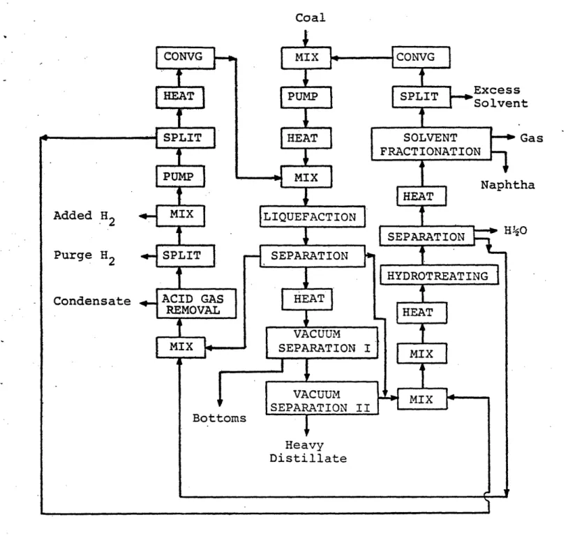
1.3 SIMULATION OF THE EXXON DONOR-SOLVENT PROCESS
The Exxon Donor-Solvent Process is a coal liquefaction
process utilizing molecular hydrogen in addition to a
hydrogenated solvent as the hydrogenating vehicle. The major advantage of the process is that it can be operated at relatively low pressures (100 bar) as compared to conven-tional processes which operate at 200 bars and above. It also separates the catalytic hydrosection step from the
liquefaction reaction.
Exxon has been conducting bench-scale research on the
process since 1966. In July, 1975, l1ton/day pilot plant. was completed and put in operation. A flow sheet of the process is shown in Figure 1.4 and a block diagram for simulation is shown in Figure 1.5.
In addition to blocks developed for the HYGAS process the various units required the EXXON Donor Solvent Process are listed below:
MIXING UNITS - these combine several streams into one
out-let stream. They can be classified according to the number and type of phases present. In this process we have mixing units that handle -the following phases: G/G, G/L, L/L, L/S, G/L,S (L = liquid, G = gas, S = solid).
SEPARATION UNITS - these separate a multiphase stream into
different streams with different phases.
·VACUUM FLASH UNITS - these separate the different components
by the increased volatility at a reduced pressure. A model
of gas/liquid/solid equilibrium is required.
SOLVENT FRACTIONATION UNIT - this separates the regenerated
solvent into different streams of different boiling range.
A Wang-Henke multicomponent distillation algorithm will
be used for the modeling.
HYDROTREATING REACTOR - this rehydrogenates the spent solvent using molecular hydrogen. The model for this reactor is a
fixed bed catalytic reactor.
LIQUEFACTION REACTOR- this carries out the central reaction
of coal liquefaction using a catalyst. The model for the
reactor would depend on the knowledge of the exact type of
reactor used in the pilot plant.
The modeling of the process has been hampered by the
lack of access to data collected by Exxon. To overcome this
difficulty a meeting between Exxon representatives, ERDA
personnel and ASPEN staff members was held in May at the
Exxon Research Engineering Company in Florham Park, New
Jersey. It was concluded that M.I.T. Would be required to enter into a secrecy agreement with Exxon in order to protect the proprietary data essential to carry out the simulation. The modeling effort at Exxon was also discussed. Currently a legal agreement is being worked out to obtain the data
Current work is being carried out with the available (published) data. Two areas are being investigated. First, the applicability of FLOWTRAN to simulate those parts of the process involving only liquids and gases. Secondly the ability of current thermodynamic property estimation techniques to predict properties of coal derived liquids is being studied.
1.3.1 Properties of Coal Derived Liquids
No correlations are available in the literature to predict the properties of coal derived liquids which are
complex mixtures of a large number of hydrocarbon components. The synthetic crude produced from coal contains a higher
percentage of cyclic compounds than natural crude. In the absence of any data, it appears the best method would be to use the methods applicable to petroleum fractions.
Accordingly, the coal liquid can be characterized by breaking it up into a number of boiling fractions and then using the petroleum correlations to predict the properties of each of these cuts. In order to validate this approach it is necessary to obtain some experimental data such as vapor liquid equilibrium data. It is expected that Exxon will be able to provide the necessary data and guidance in predicting physical properties.
1.3.2 FLOWTRAN Simulation of the EDS Process
A part of the Exxon Donor-Solvent (EDS) process has been simulated using the FLOWTRAN process simulator. The liquid was divided into ten boiling fractions and properties of each cut was generated using the petroleum correlation built into FLOWTRAN VLE program.
The part of the process (not involving solids) which was simulated using FLOWTRAN is shown in Figure 1.6. This represents the solvent separation section of the pilot plant. Figure 1.7 shows the FLOWTRAN Block diagram. In all cases, the simplest of the FLOWTRAN blocks were used in the simula-tion. No comparison with actual pilot plant data can be provided since the latter is not available until the secrecy agreement with Exxon is signed.
1.4 SIMULATION OF THE C02-ACCEPTOR PROCESS
(This simulation is being carried out at the
University of Pennsylvania under a subcontract.)
The C02-Acceptor process for coal gasification is being developed by the Conoco Coal Development Company. A pilot plant of the process has been operated at South Dakota.
A flow sheet of the C02-Acceptor process is shown in
Figure 1.8. Raw lignite from the mine is trucked to the lignite storage and handling section, a system of conveyors which transport coal among storage areas. The lignite is
Gas 700 1500 H20 Recycle Solvent H20 Naphtha Solvent Gas Gas 5. p 400
(0-4.3) 'C-+'
z
.43 Cr4
4 >~ P-4 0 (a rtZf w u so LO I 00
m/ U3 03 'J0
cu n U r-4' (/20 m r. H. :3
0
-,4 to 'U 0 r4 41) rq PT4 co n O d E o i .to4 -.e C r-T~ 0 04V 4 3: 4. a
.f-0 .f-0
4 r) v C/hio
>1 :3 0 44 >HO
C120U} a) 0 O0 O2 4 O a a 4 --0 4 .44*H E 0 H 0 Q-T .H r-t O3
---o X CO 0 0 P4 -0 04 0a
0
440
u -t C) 40J U .r-aco 0 -4 .r4 0 43 -H 0 . .r4 4Ji tO .(iU -"I 44 .k '-Px z-o 0 O O -4 -t-4I- · r 4-JU 'IZ r 4 c) = C >1 0 S C I 0 aC 'ri 0 0 04 .,-14 0 'ti 0 tn CD-u 0 ro .=1 Ut0
:(TA rZ4 4J .U 0 14 -4 0 .-H-r~~~~~~~C
0 02 'TL
1o O0
a G0 4J -,-i 0 Z CD 0 -4i .-H rzl 0 0l 0 Q3 ,J 0 54u
O r.) U 4 to 0 0 0 -N- 444 U -* C) J -IH 0 Z 0 4-) -H .-F
0 4.J -H -Cn .I-9r of---.4J G-o0 0 -z0'-I .l 4 t4 w k4 o H CD ru r O ·rq ~::; m I r: ID m -H -. . -- -. ....- I II I !l.I Il~lI 1 -- -I l _ . i I N , - s" -II
l NoLLIII a d M a) fand preheated. It is fed to the gasifier where it reacts with steam in the presence of calcined dolomite. Dolomite absorbs CO2 and H2S in the gasifier and produces a hydrogen rich product low in H2S. Spent dolomite is regenerated to drive off CO2 by burning char in the regenerator. Since
H2S is not recovered during regeneration, some spent dolomite is removed for sulfur recovery. Hence, make-up dolomite is added from the dolomite preparation and handling section. Waste solids (principally ash) are removed from the gasifier
and regenerator overhead streams, combined with reject dolomite, and sent to the waste solids treatment section. Here, spent dolomite is reacted with CO2 to release H2S which is sent to the sulfur recovery section. Product gas
from the gasifier is purified to remove CO2 and H2S and sent to the methanation and dehydration sections. Since CO2 is absorbed by dolomite in the gasifier and H2 is produced, a process for shift conversion is not necessary.
We are currently modeling the lignite pretreatment and gasification processes.
1.4.1 Description of the Lignite Pretreatment and Gasification Processes
The following description of these processes parallels that in ERDA Report, ERDA-76-58, FE-2083-7.
The lignite pretreatment section of the process includes grinding, drying and preheating. A block flow diagram for the
pretreatment section is shown in Figure 1.9. Lignite from storage is fed to receiving hoppers and from there to the primary
crusher where it is reduced to less than one inch. Crushed lignite is transported to hot gas swept hammer mills where it is ground to less than one eighth inch. Hot flue gas from the
furnace is mixed with overhead recycle gas to maintain the mill
inlet temperature at 600F and reduce the moisture content of lignite from 40 to 20 percent. After gases are cleaned in cyclones, some lignite is sent to furnaces for combustion and the remainder proceeds to flash dryers, where it is contacted
with hot flue gas and its moisture reduced to 5 percent. Finally, at 200°F lignite is sent to a fluidized bed preheater where it is heated to 5000F and remaining moisture removed. The pre-heated lignite is.then transported to the gasification process.
The block flow diagram for the gasification flowsheet is shown in Figure L10. Preheated lignite is fed to fluid bed
gasifiers by lock hoppers. Calcined dolomite from regenerators and steam are added and gasification takes place at 15500F and
150 psig. The dolomite: (1) carries heat to the gasifier, (2) absorbes CO2 by the exothermic reaction:
MgO CaO + CO2 + MgO CaCO3
and (3) absorbs H2S by the reaction: MgO CaO + H2S + MgO CaS + H2 0
4.i 0 a) (a 54 a) a) )
0.9
-rH 0 -r4 C 0 a) 4u r) Q) a) 5-4 c) 4 *r4 14 0 5-4 (z u2V25 41 .A 0 N. H 0 .r4 4J 0 (] o.l 4J (TS-r4 tU
0
0 .3-,' 0-,-0
(d 4.0
tn r-i 144.4 .34 r4 a a 11 ,4 -4 a a aNote that absorption of C02 in the gasifier forces the water gas shift reaction,
CO + H20 CO2 + H2
to the right, and eliminates the need for a separate shift conversion process. Spent dolomite is transported to regen-erators where C02 is removed at 18590F with heat supplied by
burning char. Entrained ash and dolomite are separated from the regenerator off gas in cyclones. The remaining gas is sent to an energy recovery section where waste heat is
recovered, residual carbon monoxide is burned, and power is recovered in gas expanders. The gasifier product gas passes through a cyclone, waste heat boiler and a quench tower where ammonia is removed. The cooled product gas at 2300F is sent to the purification section.
1.4.2 Work Accomplished
An early step in modeling the C02-Acceptor Process
involved preparation of information flow diagrams that show process units for which computer models are required. These diagrams are illustrated in Figures 1.9 and 1.10. The work has concentrated(n preparing models for process units that handle solids such as the crusher, gas swept hammer mill, cyclone,
gasifier, and regenerator. It is planned to use existing programs to model process units involving vapors and liquids, wherever
To minimize efforts, the use of FLOWTRAN was explored for simulation of process units involving the vapors and liquids. PLEXSYS would represent the data structure for the entire pretreatment and gasification sections. Programs for simulation of process units involving solids would
incorporate this data structure, while data for process units involving vapors and liquids would be converted to a form compatible with FLOWTRAN building-blocks. Also, pro-grams to estimate properties of vapors and liquids within FLOWTRAN would be called from programs to model solids-handling equipment, such as driers.
A short period was devoted to determining the feasibility of using PLEXSYS with the FLOWTRAN system, after which it
was decided to proceed with this promising approach. Details of the Job Control Language to link PLEXSYS routines with FLOWTRAN will be worked out during the simulation period in July and August.
A model to simulate milling was completed in May. It predicts the particle size distribution of the product
stream and the energy requirements of the mill. Specifica-tions are characteristics of the input stream, the mill breakage function, the selection function, and the
class-ification function. For details of the solution method, see Perry's Handbook (1973) and the paper by Masson and Sligar (1974).
A model to simulate drying of solid particles has' been completed. It involves simultaneous heat and mass transfer within spherical particles. The model is similar to that developed by Mcintoch (1976).
Dr. Joseph Maskew of Conoco, at Library, Pennsylvania, provided a copy of his computer program (in the BASIC
language) to model the gasifier and regenerator. This
model is expected to be suitable for use in our simulation. The program will be converted to FORTRAN and the plex data
structure incorporated.
1.5 WORK FORECAST
The prototype simulator PLEXSYS II will continue to
be updated to meet the requirements of the three simulations. An updated version of the User's manual and Systems manual will be issued in the next quarter to document all the
changes made. Input/output facilities and debugging features will be improved to facilitate the simulations.
1.5.1 Simulation of the HYGAS Process
This work is planned to be completed in the next quarter. The immediate goal is to complete simulation of sections of the plant before simulating the integrated pilot plant. After the simulation has been completed, the effect of
important process variables on product yield will be studied. Sizing blocks will be written for major pieces of equipment.
1.5.2 Simulation of the Exxon Donor-Solvent Process Negotiations with Exxon will continue during this quarter to obtain the proprietary process data under a secrecy agreement. FLOWTRAN simulation studies will be continued for those sections of the plant not involving solids. Investigations on the physical property estimation of coal derived liquids will continue over the next quarter.
1.5.3 Simulation of the C02 Acceptor Process
The development of models for the Cyclone Separator, Furnace, Flash Drier and Preheater, Gasifier and Regenerator will be carried out in the next quarter; The simulation of the entire process is expected to be completed in August, 1977.
TASK 2, DEVELOPMENT OF ASPEN SYSTEM STRUCTURE... .1 . . .E.
2.1 WORK ACCOMPLISHED
An advisory committee consisting of representatives of
industry, government, and universities was formed to guide
development of ASPEN and to insure that it will meet the
needs of the ultimate users. A list of names of members
of this committee is given in Table 2.1. The first meeting was held on December 13, 1976.
Three task forces of the advisory committee were formed to assist with specific aspects of the project. These are:
(1) Task Force on System Design - will make
recommenda-tions regarding design criteria for the system and proposed
approaches. It will review the work on the project staff as the system design emerges.
(2) Task Force on Software Evaluation - will help to
identify existing software and devise means of comparative evaluation for potential use in the system.
(3) Task Force on Benchmark Problems - will consider
the ultimate end use of the system and devise benchmark
prob-lems typical of those the system will be expected to solve. The problems will guide development of the system and serve
as tests of it when completed.
Other task forces may be needed and will be created on an ad hoc basis. The task forces may draw upon the project
Each of the task forces met separately as working groups
and prepared preliminary reports which were included in the
Third Quarterly Progress Report.
A list
of
preliminary design criteria has been prepared
and is being sent out
to
all members of the Advisory Committee
in the form of a questionnaire shown in Figure 2.1. The
objective is to get as much input as possible from industry (the ultimate user of ASPEN) early in the design stage so
that ASPEN, when developed, would meet both industry's and
ERDA's needs.
We have engaged the services of Softech, Inc., a
software consulting company, to aid in the development of the system. We are in the process now of preparing a
subcon-tract to Softech. Softech will bring extensive experience
in the design and implementation of large software systems. The specific tasks to be assigned are: (1) Help determine the functional requirements of the system. (2) Provide assistance in the design of the system. (3) Assist in the
examination of software products proposed for acquisition
(4) Help establish an appropriate design environment and (5) Provide assistance in project planning and scheduling.
2.2 WORK FORECAST
The questionnaire replies from the members of the Advisory Committee will be analyzed. Based on the conclusions, the
Committee on User/Use Profile of the System Design Task Force will be held in August in order to discuss the
functional specifications and its impact on the user.
The implementation of the system structure will begin in the second quarter of the second year.
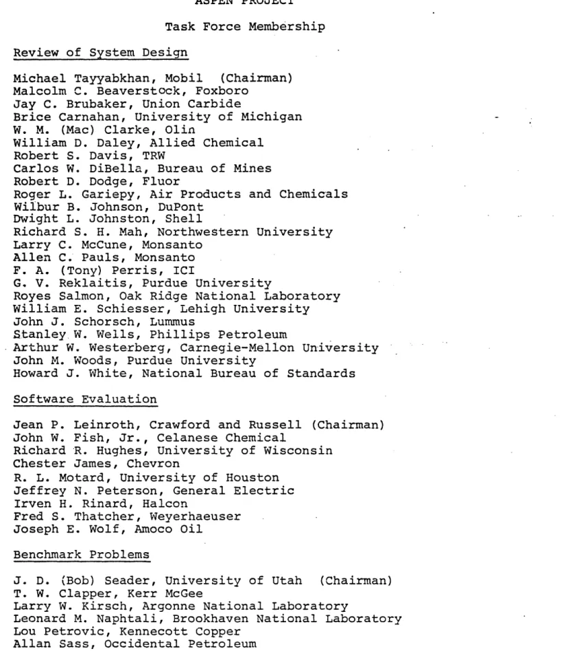
TABLE 2.1
ASPEN PROJECT
Task Force Membership Review of System Design
Michael Tayyabkhan, Mobil (Chairman) Malcolm C. Beaverstock, Foxboro
Jay C. Brubaker, Union Carbide
Brice Carnahan, University of Michigan W. M. (Mac) Clarke, Olin
William D. Daley, Allied Chemical
Robert S. Davis, TRW
Carlos W. DiBella, Bureau of Mines Robert D. Dodge, Fluor
Roger L. Gariepy, Air Products and Chemicals Wilbur B. Johnson, DuPont
Dwight L. Johnston, Shell
Richard S. H. Mah, Northwestern University Larry C. McCune, Monsanto
Allen C. Pauls, Monsanto F. A. (Tony) Perris, ICI
G. V. Reklaitis, Purdue University
Royes Salmon, Oak Ridge National Laboratory William E. Schiesser, Lehigh University John J. Schorsch, Lummus
Stanley W. Wells, Phillips Petroleum
Arthur W. Westerberg, Carnegie-Mellon University
John M. Woods, Purdue University
Howard J. White, National Bureau of Standards Software Evaluation
Jean P. Leinroth, Crawford and Russell (Chairman) John W. Fish, Jr., Celanese Chemical
Richard R. Hughes, University of Wisconsin Chester James, Chevron
R. L. Motard, University of Houston Jeffrey N. Peterson, General Electric Irven H. Rinard, Halcon
Fred S. Thatcher, Weyerhaeuser Joseph E. Wolf, Amoco Oil
Benchmark Problems
J. D. (Bob) Seader, University of Utah (Chairman) T. W. Clapper, Kerr McGee
Larry W. Kirsch, Argonne National Laboratory
Leonard M. Naphtali, Brookhaven National Laboratory Lou Petrovic, Kennecott Copper
Task Force Membership, continued
Advisory Committee Only (No Task Force) Edward Abate, Sun Company
Robert Barneson, Fluor William M. Hathaway, Fluor E. B. Kretzmer, Exxon *
Kennard F. Stephenson, Jr., Allied Chemical Matthew G. Zellner, Air Products and Chemicals
REPLY FORM
Preliminary Design Criteria for the ASPEN System
Name of person completing form
Company and Address
Telephone Number
Which activities related to process simulation have you been involved
in within the past ten years? Comment on extent of your involvement, which
simulator(s), etc.
Used a Process Simulator
a- Developed a Process Simulator
E]Assisted Others to Use a Process Simulator
Z Taught Courses on Process Simulation
L
Conducted Research in Process Simulation2
Managed any of the above activitiesOther activities may be described below:
-I_
Please answer the following questions to help resolve some specific issues.
If a question is unclear or of no interest to you, leave it blank. Comments
are welcome.
1. If ASPEN were available today and were installed in your company or organization, what is the most likely computer system that, woul.d be used?
Computer(s) (Make and Model)
,~~ ~ , , . .,
Operating System and / or Comments
I. . . ..
Maximum Allowable Core Region (if known)
., . ,
2. Is it important that parts
Yes No
of ASPEN be usable on a small computer?
If so, what is the smallest computer you would envision using?
3. What language(s) [FORTRAN, PL/l, other] would you prefer or recommend (if any) for:
(a) The executive program (preprocessor, command
interpreter, etc.) (b) The building blocks
(unit operations modules, property routines, etc.)
4. What method(s) of input should be provided:
not
needed essential
(a) Batch input by means of card reader (b) Input by keyboard terminal
5. How important is it to provide:
(a) fixed-format fill-in-the-blanks input
(b) free-formal flexible input
6. What extent of interaction should be provided?
(a) Interactive entry and editing of input (b) Prompted input 1 2 3 4 5' 1 2 3 4 5 not needed essential 1 2 3 4 5 1 2 3 4 5 not needed essential 1 2 3 4 5 1. 2 -3 4 5
(c) Interactive input checking (for
consistency, bounds, etc.) 1 2
(d) Display of intermediate results
during execution 1 2
(e) Redirection of simulation during
execution (e.g. for convergence) 1 2
(f) Interactive examination of selected output 1 2
7. Which of the following computational architectures should for solving the steady-state simulation problem?
(a) Sequential-modular (as in FLOWTRAN,
DESIGN, SSI/100) where separate routines for each unit operation 'compute output stream variables as functions of input stream variables and unit parameters. Routines are called in sequence and
not eeded 3 4 5 3 4 5 3 4 5 3 4 5 be implemented essential r n(
(b) Simultaneous-modular where separate routines are provided as for sequential-modular, but they are called (in any order) to compute coefficients in linearized process model. Linear equations are solved and the process is repeated until convergence.
(c) Equation-oriented (as in SPEED-UP and GENDER) where models of process units are in form of (nonlinear) equations. Complete set of equations is generated for the process and fed to general-purpose nonlinear equation solver with automatic partitioning and tearing.
8. For the sequential-modular approach, should calculation order?
not
needed essential
1 2 3 4 5
1 2 3 4 5
the system determine the
[I definitely no
[1] leave as an option
oI definitely yes
9. What features of simulators you have used have been particularly good or bad (indicate which).
A number of features proposed for ASPEN
have been listed below in six categories
relating to different functional criteria.
For each feature or criteria, you are
asked to indicate by circling a number whether it should have a high, average, or
low priority. Even though some features are dictated by the needs of ERDA, we would like an indication of how important they are to you or your organization.
If a question is unclear or of no interest to you, leave it especially welcome. Write them on the back of the sheet or
if you need additional space.
blank. Comments are on a separate page
I. CRITERIA FOR CALCULATIONAL CAPABILITIES
10. The System Must Be Able to Perform the Following Types of Flowsheet Analyses:
.(a) Steady-State Process Si:mulation (b) Equipment Sizing
(c) Economic Evaluation
11. The System frust Permit Analyses of Flowsheets with Differenrt Types of Streams.
(a) Conventional Vapor-Liquid Streams (b) Streams Contailning Solids
(c) Multi-Phase Vapor-Liquid Solid Streams
(d) Energy Streams (e) Information Streams
(f) User Defined Streams Containing Arbitrary. Sets of Variables
12. The System Should Estimate Physical Properties of: (a) Gases
(b). Liquids (c) Solids
(d) Multi-Phase Mixtures (e) Heterogeneous Materials
(f) Complex Materials (Large lumber of
Chemical Con:ponents) (9) (h) (i) Coal-Derived Liquids Shale-Derived Liquids
Other Fossil Fuel Intermediates
. .
13. The System Should Provide Automatic Regression
(under user control) to Determine Model Parameters (a) Physical Property Coefficients Regressed
from xperimental Data (such as VLE data) (b) Unit Parameters Regressed from Process
Operating Data
(c) Coefficients in Simplified Process Models (such as linear or polynomial approximations) Regressed from Results of Multiple Runs with
PRIORIT' average 1 1 1 2 3 2 3 2 3 Y h. igh 4 5 4 5 4 5 1 2 3 '4 5 1 2 3 .4 5