Publisher’s version / Version de l'éditeur:
Vous avez des questions? Nous pouvons vous aider. Pour communiquer directement avec un auteur, consultez la première page de la revue dans laquelle son article a été publié afin de trouver ses coordonnées. Si vous n’arrivez pas à les repérer, communiquez avec nous à [email protected].
Questions? Contact the NRC Publications Archive team at
[email protected]. If you wish to email the authors directly, please see the first page of the publication for their contact information.
https://publications-cnrc.canada.ca/fra/droits
L’accès à ce site Web et l’utilisation de son contenu sont assujettis aux conditions présentées dans le site LISEZ CES CONDITIONS ATTENTIVEMENT AVANT D’UTILISER CE SITE WEB.
Fire Study (National Research Council of Canada. Division of Building Research), 1968-01-01
READ THESE TERMS AND CONDITIONS CAREFULLY BEFORE USING THIS WEBSITE. https://nrc-publications.canada.ca/eng/copyright
NRC Publications Archive Record / Notice des Archives des publications du CNRC : https://nrc-publications.canada.ca/eng/view/object/?id=25801830-7aae-47c6-aaaf-3eb76f83c0f4 https://publications-cnrc.canada.ca/fra/voir/objet/?id=25801830-7aae-47c6-aaaf-3eb76f83c0f4
NRC Publications Archive
Archives des publications du CNRC
For the publisher’s version, please access the DOI link below./ Pour consulter la version de l’éditeur, utilisez le lien DOI ci-dessous.
https://doi.org/10.4224/40001365
Access and use of this website and the material on it are subject to the Terms and Conditions set forth at
Fire tests of eight wide-flange steel columns protected with
gypsum-sanded plaster
NATIONAL RESEARCH COUNCIL OF CANADA DIVISION OF BUILDING RESEARCH
F m E TESTS OF EIGHT WIDE-FLANGE S T E E L COLUMNS
PROTECTED WITH GYPSUM-SANDED PLASTER
W . W. Stanzak F i r e Study No. 20 of the Division of Building R e s e a r c h Ottawa January 19 68
FUXE TESTS OF EIGHT WIDE-FLANGE STEEL COLUMNS
PROTECTED WITH GYPSUM-SANDED PLASTER
This r e p o r t describes a s e r i e s of eight f i r e t e s t s con- ducted on steel-column sections protected with gypsum-sanded plaster. The t e s t s f o r m p a r t of a m o r e extensive investigation of
sand/aggregate/plaster protection under way in the F i r e Research Section a t the Division of Building Research.
One purpose of the t e s t s was to provide f i r e performance information for columns protected with gypsum- sanded plaster through- out the range of thickness that might normally be encountered in p r a c - tice. A second objective was to obtain data on the influence of c r o s s - sectional size and shape on f i r e endurance time. The fir s t six t e s t s were confined to plaster thicknesses of l e s s than 1 in. a s i t was thought that spalling might make g r e a t e r thickness impractical. The complete absence of any spalling during the f i r e tests, however, led to two
additional tests, with protective covers up to 1 112-in. thick.
The t e s t s were c a r r i e d out in the DBR Floor Furnace and the specimens were not loaded. A detailed description of the f i r e t e s t facilities a t the National Research Council i s available (1).
DESCRIPTION OF TEST SPECIMEN
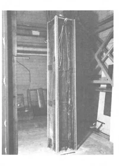
The dimensions and weight of the column sections a r e given in Table I. Construction details of a typical t e s t specimen a r e shown in Figure 1; a column prepared f o r plastering in Figure 2; two completed t e s t specimens p r i o r to installation in the furnace, in
F i g u r e 3; and a view of the t e s t specimen installed in the furnace p r i o r to the f i r e test, in Figure 4.
The i t e m numbers below correspond to the p a r t numbers in Figure 1.
1. Wide-flange s teel column section: 8 ft-4 in. long, Steel Specification ASTM A36-61T ( s e e Table I for details).
*
Steel Industries Fellow. Division of Building R e s e a r c h ( f i r s t holder of an industrial fellowship established by the s teel industry of Canada a t the National Research Council).2. F u r r i n g channels: 3 /4 in. by 3 18 in. by 18 gauge (0.048 in. ),
supplied in 12-ft lengths, cold-formed channel sections weighing 230 lb p e r 1000 lin f t and painted with r e d lead oxide paint.
Vertical and hdriz;ontal furring was tied with t h r e e loops of 18 gauge soft galvanized tie wire.
3. Expanded-wing c o r n e r beads: 2 112 in. by 2 112 in., w e r e attached to each c o r n e r to provide the d e s i r e d plaster thickness. F o r columns 7 and 8 m e t a l lath s p a c e r s w e r e used to locate the c o r n e r beads to give the required depth of plaster. Figure 5 shows column 7 after the application of the furring, m e t a l lath, and corner beads. Note m e t a l lath s p a c e r s under c o r n e r bead. 4. Diamond m e s h m e t a l lath, in sheets 8 f t long by 27 in. wide,
weighing 2.5 lb p e r s q yd, was applied either vertically o r horizontally, depending on which was m o s t convenient f o r the dimensions of the column. The m e t a l lath was tied to the furring with a single loop of 18-gauge (0.048 in.) galvanized wire, spaced approximately 6 in. apart. The joints in the lath were lapped
approximately 1 in. over supports. Where the joints w e r e not over supports, the laps w e r e approximately 4 in. and securely tied. 5. Scratch coat, 1 p a r t gypsum: 2 p a r t s sand (by weight)
Average density: 105 lb/ft3
Average compressive strength of four cylinders: 419 psi.
6.
Brown coat, 1 p a r t gypsum: 3 p a r t s sand (by weight)Average density: 105 l b / f t 3
Average compressive strength of four cylinders: 473 psi.
7. End caps: two p e r specimen, cut f r o m 3 14-in. thick plate having dimensions X by Y, a s shown in Table I and F i g u r e 1. End caps w e r e welded to the sections with a 3 18-in. f i l l e t weld a l l around. 8. T i e wire (not shown): No. 18 Imperial w i r e gauge (0.048 in. )
soft, annealed, galvanized steel. WORKMANSHIP
Furring, lathing and plastering were c a r r i e d out in accordance with the provisions of CSA Standard A82.30
-
1965 (2). The plaster wasapplied in two coats, with no finish coat.
F o r the specimens used in t e s t Nos. 1 through 6 the workmanship was average. L a r g e variations i n thickness of plaster
on the column surfaces were detected, due to c a r e l e s s application by laboratory standards of furring lath and beading.
Specimens 7 and 8, which were completed a t a l a t e r
time, were of good commercial grade workmanship. TEST METHOD
The f i r e endurance t e s t s w e r e c a r r i e d out in accordance with CSA STANDARD B54.3-1964 (3), Alternate T e s t of Protection
F o r Steel Columns. The furnace temperature was m e a s u r e d by nine
thermocouples installed in a m e t a l f r a m e constructed f r o m 13
/
16-in, OD Inconel tubes having 0.035-in. wall thickness. The location of the furnace thermocouples i s shown in Figure 6.The hot junction of the thermocouples was 12 in. away
f r o m the surface of the specimen. Both the individual temperatures a t nine points of the furnace and the average of .the nine t e m p e r s t u r e s
w e r e recorded. The fuel input to the furnace was controlled to make
the average temperature follow a s closely a s possible the p r e s c r i b e d temperature v e r s u s time curve.
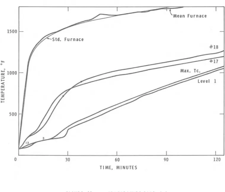
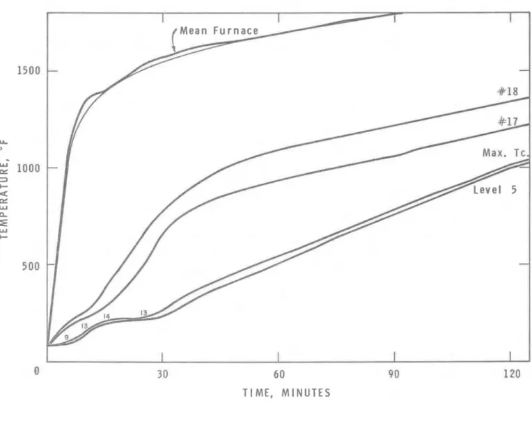
The temperature of the steel section was m e a s u r e d by fifteen thermocouples (Nos. 1 to 15, Figure 7) located in groups of
t h r e e a t five levels. Two thermocouples were on the inside of the p l a s t e r located a s shown in Figure 7.
RESULTS
The average furnace temperature during the f i r e t e s t s
was always within allowable limits. Figure 8 i s a graph showing the
temperature r i s e of the columns. Figures 9 to 15 show the f u r n a c e ' temperature, the temperature of the two thermocouples (Nos. 17 and 18) on the inside of the plaster, the maximum individual thermocouple
temperature, and the average temperature a t the hottest level f o r each
Two successive f i r e t e s t s were conducted on column 7.
During the f i r s t a malfunction of the furnace automatic temperature control caused the column to be seriously overexposed and the t e s t was discontinued. The specimen was allowed to cool and was re-tested in o r d e r to make possible an estimate of the temperature r i s e curve f o r this column. The estimate was made by combining the r e s u l t s of the re-test f r o m the point where the furnace malfunction occurred during the f i r e t e s t with those obtained on the f i r s t t e s t up to that point. The
resulting estimate i s conservative because the f i r e exposure of the f i r s t t e s t r a i s e d the thermal conductivity of the plaster.
The r e s u l t s of the column t e s t s a r e summarized in Table I. F r o m the observations taken during the f i r e tests, the r e s u l t s show a similarity in that a l l specimens had hairline c r a c k s near and parallel to the corner beading. All columns were examined c a r e - fully after the t e s t s to determine the condition of the plaster, furring and steel core. The plaster was friable, particularly the brown o r second coat. The s c r a t c h o r f i r s t coat was relatively strong. The corner beads had oxidized considerably where they were exposed to the f i r e and the m e t a l lath had l o s t i t s protective coating. The steel column section itself was not visibly affected by the f i r e exposure.
Column 5 was virtually identical to column 4, except that on No. 5 both coats of plaster were one p a r t hardwall plaster to two p a r t s sand. Upon examination after the t e s t i t was found that the plaster on column 5 was considerably stronger and l e s s friable than the plaster on column 4, but that i t had cracked m o r e a t the corners.
COMMENTS
Modern North American f i r e testing practice has favoured the u s e of 8- by 8- and 10- by 10-in. sections a s standards. Members s m a l l e r than these seldom f o r m the principal supporting m e m b e r s of a s t e e l structure. The f i r e endurance times yielded by the four t e s t s on these sections may therefore be considered for u s e directly for rating purposes. The r e s u l t s of the f i r e t e s t s indicate column protection requirements a s shown in Table I I.
I t was previously stated that a number of the sections were chosen to demonstrate the influence of column size and shape on f i r e performance. These were the 14-in. by 10-in. by 61-lb and the
12-in. by 12-in. by 190-lb sections. A measure of the compactness of a section i s given by dividing the product of its nominal dimensions by the weight per foot. As may be seen, the f i r s t section i s much l e s s compact than the other; in fact, i t i s l e s s compact than even the standard 8-in. by 8-in. by 48-lb section, The 12-in. by 12-in. by 190-lb section was chosen because i t i s one of the most compact rolled shapes available. The authors a r e not aware of any previous tests on such a heavy and compact section.
Due to the complex mechanism of heat transfer encountered with a membrane-protected column, no simple relation between column geometry and f i r e endurance can be established. I t i s interesting to note that the f i r e resistance classification for column 3 was higher than that ,
for the standard test sections. The relatively non-compact sections 4 and 5, however, still yielded a f i r e resistance rating of one hour. One may conclude from this that although the compactness of the column section
can have a significant effect on f i r e behaviour with unprotected or very
lightly protected columns, i t i s of only secondary importance with membrane protections having low thermal conductivity and a high heat capacity. That is, the effect of cross-sectional compactness or the heat capacity of the steel section decreases a s the thermal resistance and heat capacity of the cover increase. The a i r gap in a membrane-protected member may be regarded a s adding to the thermal resistance of the protective cover. (Increasing the thickness of an a i r gap does not significantly affect the thermal resistance or the f i r e endurance time of a structure.)
The compactness of steel sections used in ordinary buildings does not vary greatly, and for the sake of simplicity the effect of compact- ness may be neglected when assigning f i r e ratings. This i s particularly true when no portion of the protection comes in direct contact with the steel of the column section, and the protective material has low thermal conductivity and high heat capacity. I t should also be kept in mind that the variables involved in the plastering operation do not lend themselves to precise specification.
Sand aggregate plasters have a somewhat higher thermal conductivity than plasters with lightweight aggregates. This s e r i e s of tests
demonstrated that gypsum-sanded plaster i s suitable a s a membrane protection for column sections in that i t does not deteriorate
significantly during f i r e exposure. When applied a s a membrane protection in appropriate thicknesses gypsum- sanded plaster provides satisfactory protection against f i r e f o r periods of up to 2 hours.
Economic considerations, however, make i t unsuitable for longer periods.
CONCLUSIONS
1. Gypsum-sanded plaster applied to m e t a l lath r e m a i n s in place during f i r e exposure and in appropriate thicknesses provides satisfactory protection to steel columns f o r periods of up to 2 hours.
2 . L a r g e (heavy) columns have better f i r e endurance qualities than s m a l l shapes similarly protected. F o r gypsum-sand plaster membrane protection, however, i t i s not practical to take account of the column s i z e in assigning ratings.
3 . No simple reliable relation can be found between f i r e r e s i s t a n c e time and column size for this type of protection.
4. Protective m a t e r i a l s such a s gypsum-sanded plaster a r e con- siderably m o r e effective applied a s a membrane than applied directly in contact with the s t e e l section.
ACKNOWLEDGEMENT
The author would like to thank Mr. 0. E. Porteous of the F i r e R e s e a r c h Section for his assistance. These t e s t s were c a r r i e d out a s p a r t of a cooperative p r o g r a m of r e s e a r c h in the F i r e Research Laboratories of DBRINRC under the Steel Industries Fellow- ship arrangement with the Canadian Steel Industry.
REFERENCES
1. Shorter, G. W. and T. Z. Harmathy, F i r e Endurance T e s t F a c i l i t i e s a t the National R e s e a r c h Council. National R e s e a r c h Council,
Division of Building Research. F i r e Study No. 1, Ottawa, July 1960 (NRC 5732).
2. Specification f o r Gypsum Plastering, I n t e r i o r F u r ring, and I n t e r i o r
Lathing. CSA Standard A82.30
-
19 65, Canadian Standards As sociation,Ottawa.
3. Methods of F i r e T e s t s of Walls, Partitions, F l o o r s , Roofs, Ceilings,
Columns, B e a m s and G i r d e r s . CSA Standard B54.3
-
1964, CanadianT A B L E I
SUMMARY O F RESULTS
*
P l a s t e r thickness measured f r o m face of metal lath at9 6 points on each column, i. e. a t 24 points on each face.
J FAILURE (min) L E V E L NO. AVERAGE* MEASURED PLASTER (in. ) F I R E RESISTANCE CLASSIFICATION (hr NOMINAL PLASTER (in. )
-
T E S T NO. 518 112 518 5I
8 518 1 1-114 1-
112 X(in.) SECTION 0.62 0.42 0.59 0.61 0.57 0.88 1.14 1.43 5 5 1 3 1 65 8 5 118 7 7 67 122 9 4 136 1 1 1-112 1 11 %'(hi.) 8" x 8 " x 481b OUTSIDE DIMENSIONS (in. ) 1 5-
2 11-112 2 3 4 5 6 7 8 1 2 1-
112 2 .' 11-112 x 12-112 16 1 6 x 18 12" x 12" x 190 1b 12" x 12" x 190 1b 14" x 10" x 61 1b 14" x 10" x 61 1b 1O"x 1 0 " ~ 112 1b 8 " ~8 " ~4 8 1 b 10" x 10" x 112 1b 15 112 15 112 14 14 14 11 14 1 6 18-112 1 8 a 1 / 2 141112 11-112 14-112 16-318 x 18-118 1 8 x 13-112 18 x 13-112 1 6 x 14-112 12 x 12-112 1 6 x 17TABLE I 1
FIR,E RESISTANCE OF STEEL COLUMNS PROTECTED WITH GYPSUM-SANDED PLASTER
PLASTER THICKNESS (IN. ) 112 5 1 8 1 - 1 1 8 1 - 1 1 2 FIRE ENDURANCE RATING (HR) 314 1 1
-
1 1 2 2._--
THERMOCOUPLE JUNCTION
FIGURE
6
FURNACE THERMOCOUPLE LOCATIONS
8 R 4026 - 2DISTANCE FROM THE BOTTOM PLATE Level 5 , 2 ' - 1 ~ / ~ " Level 4
,
3'- 1V4" Level 3 , 4'-11/4" Level 2,
5 '-
1 I/+" Level I,
6'-
1 114FIGURE
7
LOCATION OF THERMOCOUPLES
eR 4 O P 8 -31 7 ( E s t i m a t e d ) C r i t i c a l T e m p e r a t u r e A S T M E 1 1 9 , C S A B 5 4 . 3 6 0 9 0 T I M E , M I N U T E S F I G U R E 8 A V E R A G E T E M P E R A T U R E R l S E C O L U M N S U R 4026 - 4
60
T I M E , M I N U T E S
F I G U R E 9 T E M P E R A T U R E R l S E # 1
e a n F u r n a c e
30 6 0 90
T I M E , M I N U T E S
F I G U R E 10 T E M P E R A T U R E R I S E # 2
Mean Furnace
60
TI ME, MINUTES
FIGURE 11 TEMPERATURE R l S E 9 3
30 60 90 T I M E , M I N U T E S
F I G U R E 12 T E M P E R A T U R E R l S E 4
I
30 60 90 120
T I M E , M I N U T E S
F I G U R E 13 T E M P E R A T U R E R l S E 5 # I 4006 - 0
i
0 3 0 60 90 120
TIME, MINUTES
FIGURE 14 TEMPERATURE R l S E