HONEYCOMB SANDWICH PANELS
byMichael Garcia-Lopez Toribio B. S., Mechanical Engineering United States Naval Academy (1997)
Submitted to the Department of Aeronautics and Astronautics in Partial Fulfillment of the Requirements for the Degree of
Master of Science
in Aeronautics and Astronautics at the
Massachusetts Institute of Technology June 1999
© 1999 Massachusetts Institute of Technology All rights reserved
Signature of A uthor ... ...
Department of Aeronautics and Astronautics May 7, 1999
Certified by... ... ... Spea Esther and Harold E. Edgerton
Associate Professor of Aeronautics and Astronautics Thesis Supervisor
Accepted by ... ...
Jaime Peraire
Associate Professor of Aeronautics and Astronautics Chairman, Department Graduate Committee
MASSACHUSETTS INSTITUTE OF TECHNOLOGY
A U
JUL 1
5 1999
HONEYCOMB SANDWICH PANELS
by
Michael Garcia-Lopez Toribio
Submitted to the Department of Aeronautics and Astronautics on May 7, 1999 in Partial Fulfillment of the
Requirements for the Degree of Master of Science in Aeronautics and Astronautics
ABSTRACT
Experimental and numerical work was conducted to understand better the compressive response of notched composite sandwich panels. The quasi-static uniaxial compressive response of notched (circular through hole) E-glass/epoxy-NomexTM sandwich panels were studied experimentally. Two different woven fabric architectures were examined. The key failure mechanism was observed to be linear damage zones (LDZs) emanating from the notch tip (in both materials). LDZ's behaved in a macroscopically similar manner to a bridged crack under tensile loading, and were characterized by semi-stable propagation.
Cross-sectioning studies revealed the key damage mechanisms operating within the LDZ. Progressive cross-sections indicated that individual fiber microbuckling led to out-of-plane warp tow kinking. The LDZ wake was characterized by kinking in all warp tows and transverse tow splitting. Strain gages were used to measure the in
situ damage zone tractions as the LDZ propagated across the width of the
specimen; a softening trend was observed.
Consistent with observations, a two parameter linear strain softening traction law was used to model the LDZ constitutive behavior. The traction law was treated as a material property. The damage zone modeling (DZM) framework was investigated to determine its validity, specifically its ability to predict three experimentally observed phenomena: the notched strength, local strain
distribution, and LDZ growth characteristics. A self-consistent physically-based model should be able to predict all three phenomena. Two models were created in order to interrogate the DZM. The damage growth model was used to determine the ability of the DZM to predict the LDZ growth behavior and notched strength. A finite element model that used discrete nonlinear springs in the wake of the LDZ to model the LDZ as a continuous spring, was implemented to determine if the DZM could predict the local strain distribution. Results showed that the current traction law provided excellent agreement with the phenomenon used to calibrate the traction law, for all specimen sizes. Extension of predictive power to other phenomena resulted in weaker correlations. The modeling framework and methodology established provide a robust tool for investigating the potential of
adding physical bases to the DZM. Thesis Supervisor: S. Mark Spearing
Title: Esther and Harold E. Edgerton Associate Professor of Aeronautics and Astronautics
I really want to extend a heartfelt thank you to all of you who made this possible- the people make it worth it. If I forget to mention someone, I'm sorry, but you know I didn't do it on purpose.
The first thanks goes out to my advisor, Professor Spearing. Thanks Mark, first for trusting me to begin this project, then for guiding me through it, and finally for the perseverance. Thanks to the other professors in TELAC who enjoy helping students: Professor Lagace, Professor Cesnik, Professor
Dugundji, and Professor McManus. Thanks also to Deb and Ping and especially Liz Zotos for getting me in here!
And thank you to those who also helped on the technical stuff: Michael Abruzzese, Jee Bang, Ariela Gruszka, Staci Jenkins, John Kane, Seth Kessler, Professor Link (USNA), Eric Martin (SDRC), Thad Matuszeski, Jose Mirazo, Lenny Rigione, Catherine and Wynn Sanders, Yong Shi, and Dong-Jin Shim.
I want to thank all of the students in TELAC. Especially "the
micky-ficky man, big booooy!!!!" Jose Mirazo. Thanks for everything my friend, and I'll
see you in Spain? Also the ones who helped to focus on things other than work: Dennis Burianek (Pole Position); Tom Reynolds, Troy Hacker, Mevlut Oenkal, and Jason Richards (all for IM football); Brian Wardle (the squat rack); DJ (Dodgers?); Gordon Maahs (Wachusett). Thanks also to Cyrus Jilla.
And I can't forget John & Gina Raimondo. Thank you for trying to round me out. The Obandos (and Pam, of course), thank you for everything, I appreciate it!
thanksgiving, I thank my family. All of you are a constant inspiration for me, thank you, I love you, and this is for you.
A special thanks to my spiritual director Father Wright, O. M. V., and all
the Oblates at the St. Francis Chapel at the Pru, and the Franciscans at St. Anthony's Shrine downtown. Thank you all for helping to show me what is most important in life.
"0 give thanks to the LORD, for he is good, for his steadfast love endures forever." Ps 118:29 "For God alone my soul waits in silence, for my hope is from him. He alone is my rock and my salvation, my fortress; I shall not be shaken. On God rests my deliverance and my honor; my mighty rock, my refuge is in God." Ps 62:5-7
"And those who know your name put their trust in you, for you, 0 LORD, have not forsaken those who seek you." Ps 9:10
"'Come to me, all you that are weary and are carrying heavy burdens, and I will give you rest. Take my yoke upon you, and learn from me; for I am gentle and humble in heart, and you will find rest for your souls. For my yoke is easy, and my burden is light. "' Mt 11:28-30
"Jesus said to them, 'I am the bread of life. Whoever comes to me will never be hungry, and whoever believes in me will never be thirsty..."' Jn 6:35
"Just then a lawyer stood up to test Jesus. 'Teacher,' he said, 'what must I do to inherit eternal life?' He said to him, 'What is written in the law? What do you read there?' He answered, 'You shall love the Lord your God with all your heart, and with all your soul, and with all your strength, and with all your mind; and your neighbor as yourself.' And he said to him, 'You have given the right answer; do this, and you will live."' Lk 10:25-28
"And this is what he has promised us, eternal life." 1 Jn 2:25
"'And this is eternal life, that they may know you, the only true God, and Jesus Christ whom you have sent."' Jn 17:3
"...'Amen! Blessing and glory and wisdom and thanksgiving and honor and power and might be to our God forever and ever! Amen."' Rev 7:12
Foreword
This work was performed in the Technology Laboratory for Advanced Composites (TELAC) in the Department of Aeronautics and Astronautics at the Massachusetts Institute of Technology. This work was sponsored by the Structural Methods and Allowables (SMA) Group at The Boeing Company and the National Science Foundation under NSF CAREER Grant CMS-9702399.
List of Figures ... . ... 10
L ist of T ables... ... ... 16
N om enclature ... ... 17
1 IN TROD U CTION ... 19
2 LITERATURE REVIEW ... 22
2.1 Compression Testing Methods ... ... 22
2.1.1 Lam inates... 22
2.1.2 Sandwich Panels... 24
2.1.3 Sum m ary ... 25
2.2 Compressive Damage Mechanisms in Laminates... 25
2.2.1 Compressive Damage Mechanisms in Unidirectional Composite Laminates ... 26
2.2.2 Compressive Damage Mechanisms in Woven Com posite Lam inates ... ... 31
2.2.3 Sum m ary ... 36
2.3 Compressive Damage Mechanisms in Sandwich Panels and Other Structures ... 36
2.3.1 Compressive Damage Mechanisms in Sandwich Panels with Unidirectional Facesheets... ... 39
2.3.2 Compressive Damage Mechanisms in Sandwich Panels with Woven Fiber Facesheets ... 40
2.3.3 Compressive Damage Mechanisms in Impacted Sandwich Structures ... ... 42
2.3.4 Compressive Damage Mechanisms in Other Structures... 4 3 2.3.5 Sum m ary ... ... 43
2.4 Compressive Failure Prediction Techniques for Laminates... 44
2.4.1 Micromechanics Models ... ... 44
2.4.2 Stress-Based Models ... 45
2.4.3 Fracture Mechanics-Based Models ... 47
2.5 Compressive Failure Prediction Techniques for Sandwich Panels.... 51 2.6 S um m ary ... ... 52 3 EXPERIMENTAL PROCEDURES...53 3.1 Materials ... 53 3.2 M anufacturing ... 59 3.2.1 M achining... 59
3.2.2 Damage Incurred From Machining... ... 60
3.3 Strain G ages... ... 6 1 3.4 Compression Testing ... 68
3.4.1 Test Apparatus ... ... 68
3.4.2 Compression Test Procedure ... .... 68
3.4.3 A lignm ent... ... 72
3.5 Damage Characterization ... ... 72
3.5.1 Visual Inspection... ... 72
3.5.2 X -R adiography ... 74
3.5.3 Cross-Sectioning... 76
3.5.4 Scanning Electron Microscopy... 84
4 A N A L Y S IS ... ... 8 7 4.1 Damage Zone Modeling Overview ... ... 87
4.1.1 The Dugdale Approach ... ... 88
4.1.2 Application of Dugdale Approach to Compression ... 90
4.1.3 DZM Interrogation ... 92
4.2 Damage Growth Model ... ... ... 93
4.2.1 Assumptions ... ... 93 4.2.2 Fram ew ork ... ... 94 4.2.3 Procedure ... 101 4.2.4 Implementation ... 107 4.2.5 Calibration ... 109 4.2.6 Sensitivity... ... 109 4.2.7 N et-Section... 111
4.3.2 Construction of the Model... ... 118 4.3.3 M esh Convergence ... 19 4.3.4 Spring Law...124 4.3.5 Im plem entation ... 126 4.3.6 C alibration ... 126 4.3.7 Sensitivity...128 4.4 Summary ... 132 5 R E SU L T S ... 133
5.1 Com pressive Response ... 133
5.1.1 Global Behavior ... ... 133
5.1.2 Local Behavior ... 145
5.2 Dam age Characterization...151
5.2.1 M acroscopic Behavior...151
5.2.2 M icrom echanism s ... ... 153
5.3 Damage Growth Model ... 167
5.4 Finite Element Model... ... 181
5.5 Sum m ary ... ... 199
6 D ISC U SSIO N ... ... 200
6.1 Experimental Investigation ... ... 200
6.1.1 Test Fixture and Method... ... 200
6.1.2 Local Measurements ... 201
6.1.3 Damage Characterization ... ... 202
6.2 Interrogation of Damage Zone Model ... 204
6.2.1 Damage Growth Model ... 204
6.2.2 Finite Element Model... ... 206
6.2.3 Consistent M ethod ... ... 209
6.3 Implementation of Damage Zone Model... 230
6.3.1 Current Traction Law ... 230
6.3.2 Effectiveness of Damage Zone Model... 230
6.3.3 Real-World Application ... ... 230
7 CONCLUSIONS AND RECOMMENDATIONS... 233
7.1 C onclusions... 233
7.1.1 Experimental Investigation ... ... 233
7.1.2 Analytical Investigation ... ... 234
7.2 Recommendations for Future Work ... .... 235
7.2.1 Experimental Recommendations... ... 235
7.2.2 Analytical Recommendations... ... 236
R eferen ces ... ... 237
Appendix A SPECIMEN MEASUREMENTS... 251
Appendix B DAMAGE GROWTH MODEL... ... 259
List of Figures
Figure 2.1 Figure 2.2 Figure 3.1 Figure 3.2 Figure 3.3 Figure 3.4 Figure 3.5 Figure 3.6 Figure 3.7 Figure 3.8 Figure 3.9 Figure 3.10 Figure 3.11An illustration of some possible local modes of failure resulting from fiber microbuckling.
Possible instabilities in sandwich structures [56].
An illustration showing both sides of one M4 eight-harness satin weave ply. The warp side shows nine warp tows. The weft side shows nine weft tows.
An illustration showing both sides of one M5 four-harness satin weave ply. The warp side shows eight warp tows. The weft side shows eight weft tows.
X-radiographs before and after machining. The honeycomb core cells are accentuated due to dye penetrant absorbtion. The far field strain gages are place in a back-to-back
configuration on the front and back facesheets. Figure not drawn to scale.
Local strain gage positioning for A-series specimens. The local strain gages on specimen ADC2 were placed as shown in figure 3.6. Strain gages are numbered in ascending order beginning with the gage nearest to the hole. Figure not drawn to scale.
Local strain gage configuration for B-series specimens. Specimen ADC2 was also gaged in this manner. Strain gages are numbered in ascending order beginning with the gage nearest to the hole. Figure not drawn to scale.
Electrical tape is placed over the initial LDZ and along the line in which it will propagate. Minimal pressure is exerted on the facesheet when applying the tape. Figure not drawn to scale.
A picture showing the components of the test apparatus. X-radiograph of dye penetrant enhanced LDZ. The dye
penetrant was absorbed by the LDZ and the honeycomb core material. No damage outside of the LDZ is noted. An illustration of the different possible cross-sectioning views.
Placement of metal shim stock on facesheet. Figure not drawn to scale. 28 38 56 57 62 63 65 66 69 70 75 77 79
Figure 3.13 Figure Figure Figure 4.1 4.2 4.3 Figure 4.4 Figure 4.5 Figure 4.6 Figure 4.7 Figure 4.8 Figure 4.9 Figure 4.10 Figure 4.11 Figure 4.12 Figure 4.13 Figure 4.14 Figure 4.15 Figure 4.16 Figure 4.17 Figure 4.18 Figure 4.19 Figure 4.20
depending on the view desired. The relative positioning of the other lines, or the exact value of the dimension X are not important. Figure not drawn to scale.
Mounting of cross-sectioned specimens. Figure not drawn to 82 scale.
Dugdale modeling assumptions. 89
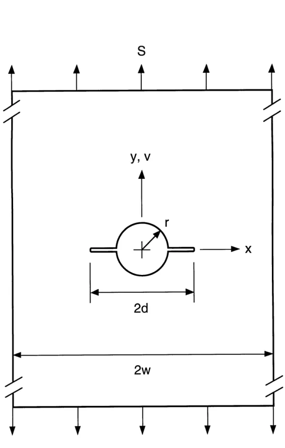
Two parameter linear strain softening traction law. 91 Geometry 1, consiting of a remote applied stress acting on a 95 finite width plate containing two symmetric cracks emanating from a circular hole.
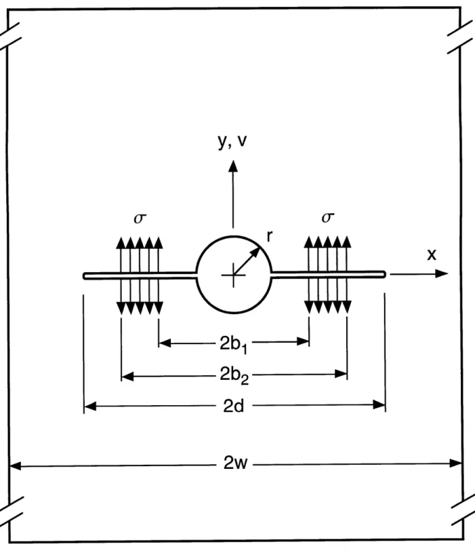
Geometry 2, consiting of a constant traction acting on a 96 portion of two symmetric cracks emanating from a circular
hole in a finite width plate.
Crack discretization. 100
COD comparison of numerical solution (reference [1161) and 102 FEM neglecting tractions for remote stress case.
COD comparison of numerical solution (reference [1161) and 103 FEM neglecting tractions for point load on crack face.
Flowchart describing damage growth model procedure. 104 Typical R-curve, with lines of Ko corresponding to constant 108 stress superimposed.
rc variation effect on model R-curve; v, = constant. 114
vc variation effect on model R-curve; c-, = constant. 115
Gss variation effect on R-curve; c, vc proportional. 116
Net-section stress. 117
Finite element mesh boundary. 120
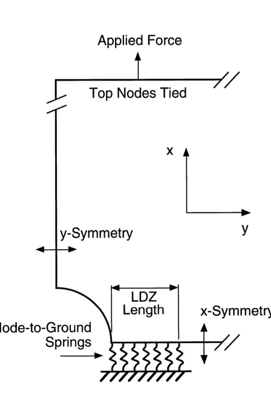
Illustration of use of discrete nonlinear node-to-ground 121 springs to model the LDZ.
Finite element model standard mesh. 122
Finite element model convergence. 123
Finite element model spring law. 125
Model spring law definition. 127
Use of local strain gage data for traction law calibration on 129 experimentally observed strains.
Figure 5.1 Figure 5.2 Figure 5.3 Figure Figure Figure Figure Figure 5.4 5.5 5.6 5.7 5.8 Figure 5.9 Figure Figure Figure Figure Figure Figure Figure Figure Figure 5.10 5.11 5.12 5.13 5.14 5.15 5.16 5.17 5.18 Figure 5.19 Figure 5.20 Figure 5.21 Figure 5.22 Figure 5.23 Figure 5.24
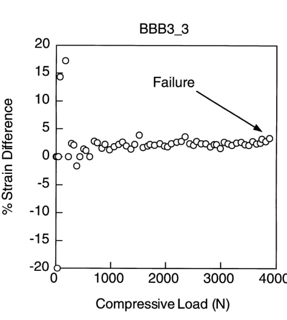
Typical data showing excellent alignment throughout the entire test.
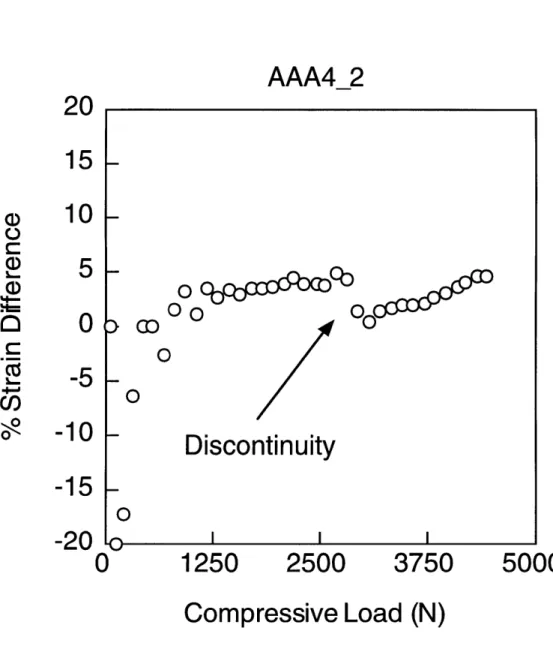
Alignment data showing sharp discontinuity resulting from manual adjustment of upper platen.
LDZ propagation effect on alignment found on some specimens.
Typical stress-strain behavior for M4 specimens. Typical stress-strain behavior for M5 specimens. Failure stress versus notch size for M4 specimens. Failure stress versus notch size for M5 specimens. M4 average initiation and failure stresses and predicted failure stresses versus notch size for both traction laws. M5 average initiation and failure stresses and predicted failure stresses versus notch size for both traction laws. Strain softening local behavior in ABB4.
Strain softening local behavior in ADC2. Strain softening local behavior in BAA2. Strain softening local behavior in BBB4. Strain softening local behavior in BDC1.
LDZs that initiated at notch tips propagating in a direction perpendicular to the applied load.
LDZ progression (1 of 2). LDZ progression (2 of 2).
LDZ propagation data indicating an initial regime characterized by toughening, after which propagation occurred at a slightly decreasing load.
LDZ propagation data indicating a relatively high initiation load. The subsequent propagation regime is characterized by an increasing load.
Cross-section showing individual warp tow fiber microbuckling in subsurface warp tow near LDZ tip.
Cross-section showing warp tow microbuckling and kinking. Cross-section showing warp tow kinking in subsurface ply. Cross-section showing shear crippling of surface ply. Cross-section showing warp tow kinking in all plies.
134 136 137 138 139 141 142 143 144 146 147 148 149 150 152 154 155 156 157 159 160 161 162 164
Figure Figure 5.26 5.27 Figure 5.28 Figure 5.29 Figure Figure Figure Figure Figure Figure Figure 5.30 5.31 5.32 5.33 5.34 5.35 5.36 Figure 5.37 Figure 5.38 Figure 5.39 Figure 5.40 Figure 5.41 Figure 5.42 Figure 5.43 Figure 5.44 Figure 5.45
Photograph of LDZ root showing shear crippling of facesheet. Scanning electron micrograph of LDZ root at hole edge in M5 facesheet. The SEM revealed weft tow splitting, a damage mechanism unobserved in M5 cross-sections.
Scanning electron micrograph of LDZ root at hole edge in M4 facesheet.
Scanning electron micrograph showing detail of kinked tow in M4 facesheet.
R-curves for AAA specimens. R-curves for ABB specimens. R-curves for ADC specimens. R-curves for BAA specimens. R-curves for BBB specimens. R-curves for BDC specimens.
Far field strain correlation of M4 specimen from FEM using traction law 1.
Local strain correlations (1 of 2) of M4 specimen from FEM using traction law 1.
Local strain correlations (2 of 2) of M4 specimen from FEM using traction law 1.
Far field strain correlation of M5 specimen from FEM using traction law 1.
Local strain correlations (1 of 2) of M5 specimen from FEM using traction law 1.
Local strain correlations (2 of 2) of M5 specimen from FEM using traction law 1.
Far field strain correlation of M4 specimen from FEM using traction law 2.
Local strain correlations (1 of 2) of M4 specimen from FEM using traction law 2.
Local strain correlations (2 of 2) of M4 specimen from FEM using traction law 2.
Far field strain correlation of M5 specimen from FEM using traction law 2. 166 168 169 170 172 173 174 175 176 177 182 183 184 185 186 187 188 189 190 191
Figure 5.46 Figure 5.47 Figure Figure Figure Figure Figure Figure 5.48 5.49 5.50 5.51 6.1 6.2 Figure 6.3 Figure 6.4 Figure 6.5 Figure 6.6 Figure 6.7 Figure 6.8 Figure 6.9 Figure 6.10 Figure 6.11 Figure 6.12 Figure 6.13 Figure 6.14 Figure 6.15
Local strain correlations (1 of 2) of M5 specimen from FEM using traction law 2.
Local strain correlations (2 of 2) of M5 specimen from FEM using traction law 2.
COD comparison for short LDZ using traction law 1. COD comparison for long LDZ using traction law 1. COD comparison for short LDZ using traction law 2. COD comparison for long LDZ using traction law 2. An example of a parabolic nonlinear spring law.
Two parameter strain softening traction law modified to allow crack overlap displacements.
COD comparison for short LDZ using traction law 1 and the CTM.
COD comparison for long LDZ using traction law 1 and the CTM.
COD comparison for short LDZ using traction law 2 and the CTM.
COD comparison for long LDZ using traction law 2 and the CTM.
COD comparison illustrating complete crack overlap for a relatively long LDZ using traction law 1 and the CTM. Far field strain correlation of M4 specimen using traction law 1 and the CTM.
Local strain correlation (1 of 2) of M4 specimen using traction law 1 and the CTM.
Local strain correlation (2 of 2) of M4 specimen using traction law 1 and the CTM.
Far field strain correlation of M5 specimen using traction law 1 and the CTM.
Local strain correlation (1 of 2) of M5 specimen using traction law 1 and the CTM.
Local strain correlation (2 of 2) of M5 specimen using traction law 1 and the CTM.
Far field strain correlation of M4 specimen using traction law 2 and the CTM.
Local strain correlation (1 of 2) of M4 specimen using traction law 2 and the CTM.
192 193 195 196 197 198 207 211 212 213 214 215 216 218 219 220 221 222 223 224 225
Figure 6.16
Figure 6.17
Figure 6.18
Figure 6.19
Figure A.1
Local strain correlation (2 of 2) of M4 specimen using traction law 2 and the CTM.
Far field strain correlation of M5 specimen using traction law 2 and the CTM.
Local strain correlation (1 of 2) of M5 specimen using traction law 2 and the CTM.
Local strain correlation (2 of 2) of M5 specimen using traction law 2 and the CTM.
Specimen measurement locations.
226
227
228
229
List of Tables
Table Table Table Table Table 3.1 3.2 3.3 3.4 4.1 Material Properties Strain Gage Positioning Test MatrixCross-Sectioning List
Traction Law and Fracture Parameters from Damage Growth Calibration
Standard Damage Growth Model Parameters Damage Growth Model Sensitivity
Traction Law and Fracture Parameters from Finite Element Model Strains Calibration
Finite Element Model Sensitivity Facesheet Initiation and Failure Loads Failure Load Correlations
Critical LDZ Length Correlations Stress-Based Failure Force Balance Measurements for AAA Specimens Measurements for ABB Specimens Measurements for ADC Specimens Measurements for BAA Specimens Measurements for BBB Specimens Measurements for BDC Specimens Table 4.2 Table 4.3 Table 4.4 Table Table Table Table Table Table Table Table Table Table Table 58 67 73 85 110 112 113 130 131 140 178 179 180 253 254 255 256 257 258 4.5 5.1 5.2 5.3 5.4 A.1 A.2 A.3 A.4 A.5 A.6
Nomenclature
Fs hole correction factor for remote stress case
F finite width correction factor for remote stress case
F orthotropic correction factor for remote stress case
Fh hole correction factor for crack traction case
F," finite width correction factor for crack traction case
Fo' orthotropic correction factor for crack traction case
G,, energy per unit area dissipated by crack propagation in steady state
Ko fracture toughness
K, corrected stress intensity factor due to remote stress
K. uncorrected stress intensity factor due to remote stress
K, corrected stress intensity factor due to crack tractions
K. uncorrected stress intensity factor due to crack tractions
S remote applied stress
V, crack opening profile due to remote stress V, crack opening profile due to tractions
a actual half crack length in Dugdale analysis
d total crack length plus hole diameter
f short crack segment distance
g, long crack segment distance
r radius
v crack opening displacement
vc maximum crack opening displacement
w facesheet half width
x, middle crack segment distance
p Dugdale plastic zone size
a stress on crack face (traction)
ac maximum traction
CHAPTER 1
INTRODUCTION
Advanced composites are currently used as standard materials in several industries, such as aerospace, sporting goods, and automotive. Due to their structural performance advantages [1-3] (e.g. tailorability of material properties, specific strength and stiffness), composites have replaced traditional metallic components and have become established as the materials of choice in some cases. Notwithstanding the current widespread usage of composites, many possible avenues of application remain unexplored. Arguably, composites' full potential, particularly in the aerospace industry, has yet to be realized.
In the aerospace industry, the design process is increasingly driven by economic considerations. To this end, composite materials have been introduced into aircraft design to reduce weight, and hence reduce fuel costs. An example of this can be found in composite sandwich structures. Composite-honeycomb sandwich panels utilize the high intrinsic bending stiffness of sandwich structures to enhance laminated composites as structural components, which by themselves are characterized by a relatively low bending stiffness. The overall weight is kept to a minimum due to the very low density of core materials. Currently, applications of honeycomb-cored composite sandwich structures range from helicopter rotor blades to secondary structures in commercial and military aircraft [4].
structures has been delayed for several reasons, including a lack of understanding, by comparison to metals, of their damage tolerance [5]. In particular, the poor performance of sandwich structures subject to severe impact loading has been a recurrent concern. This shortcoming for composite sandwich panels is a specific instance of more general limitations in the design methodology for composite structures.
Currently, the composite design process relies on a multitude of coupon-level tests to obtain a database with which to pass strength data on to progressively larger, more complex structural components. This translates into two undesirable results. First, the large amount of testing requires an equivalently large capital investment. Second, this building block type design approach does not utilize mechanism-based (or "physically-based") failure prediction models, which effectively forces the reliance on empiricism and increases the design/production time. The desire is to utilize mechanism-based models within the damage tolerant design approach to reduce costs and reduce the time within which advanced composites can be reliably and better implemented in aerospace applications [6].
Two overarching issues are addressed by the present work which result from considerations relating to the damage tolerant design approach currently used in the aerospace industry. The first issue addresses the fact that composite sandwich structures are currently in use, and the fact that mechanism-based failure prediction models do not exist. In order to apply a damage tolerant design approach, these types of models must exist [6] for any material susceptible to damage and time-dependent damage growth. The second issue addresses composites', and in the present investigation, composite sandwich panels', lack of realized potential. For example, primary structures are currently composed of metals which are heavier than composite
materials. It should be noted that mechanism-based modes do exist for metals; i.e. their damage tolerance is relatively well understood [5].
The objective of the present work is to investigate the potential for adding physical bases to the damage zone modeling (DZM) framework applicable to sandwich structures under compression. Both experimental and numerical work are conducted to this end. The experimental study focuses on characterizing the key failure mechanisms resulting from the compressive loading of notched sandwich panels with glass fiber/epoxy facesheets. The numerical study is an investigation of the DZM. Specifically, experimental observations are applied to the DZM to assess the potential of implementing the model as a design tool for the damage tolerance of sandwich panels. This work was conducted in parallel with a similar approach applied to sandwich panels with graphite/epoxy facesheets [7].
The present work is arranged as follows. Chapter 2 presents an overview of the literature pertaining to compressive tests. Previous work on test fixtures, failure mechanisms, and modeling approaches are discussed which relate to unnotched and notched unidirectional and woven composites and sandwich panels. In chapter 3, a description of the experimental procedure used in the present work is presented. The procedures governing the compression tests and damage evaluation techniques are included. Chapter 4 presents the modeling framework and details of the analysis applied to the present case. In chapter 5, the results from the experimental and analytical investigation are presented. A discussion of the results and their correlation with the modeling is presented in chapter 6, followed by conclusions from the present study and recommendations for future work in chapter 7.
CHAPTER 2
LITERATURE REVIEW
This chapter begins by reviewing established compression test methods and fixtures used for composite laminates and composite sandwich panels. Then, the key compressive damage mechanisms observed in both laminates and sandwich panels of different materials and fiber architectures are reported. Finally, a summary of laminate and sandwich panel compressive strength prediction models, is presented.
2.1 Compression Testing Methods
Several test methods and associated testing fixtures exist for both composite laminates and sandwich panels. In general, these tests have been developed either to determine the material properties of a given composite, such as modulus or compressive strength, or to assess a specimen's specific compressive response in a damaged condition, in order to assess its damage tolerance. This latter purpose reflects the observation [8] that the compressive loading response is generally more critical than the tensile loading response for damage tolerant considerations.
2.1.1 Laminates
The compressive response of composite laminates has been studied extensively over the past 35 years. This has facilitated the emergence of standardized compressive testing methods such as ASTM Standards
D3410/D3410M [9] and D695 [10]. The fixtures used in the test procedures are either designed to introduce the compressive load via shear (e.g. the Celanese and IITRI fixtures specified in D3410) or end loading (e.g. D695). Shear loading is accomplished through indirect load transfer from wedge grips, usually by loading tabs which are bonded to the laminate on either side and on both ends. Several unacceptable failure modes are discussed in D3410, such as delamination of loading tabs, through-thickness laminate failures within the gripped areas, end crushing, and delamination occurring within the gripped areas. This leads to the conclusion that the alignment and load introduction characteristics are critical in obtaining allowable compressive failure modes. The end loading method, while presented as a standard for use with rigid plastics only, is commonly used with modifications (sometimes termed "modified ASTM D 695 test methods") on composites and utilizes a supporting jig or anti-buckling guide to prevent global buckling of the laminate.
Experiments have shown that test sections larger than those specified by the standards could be used with the fixtures, as long as global buckling was avoided [11]. Furthermore, either loading scheme, shear or end loading, can be used to obtain valid compressive strength results [11]. A finite element study [12] suggested that a combined loading scenario would alleviate problems arising from stress concentrations in both the shear and end loaded fixtures; thus fixtures have been designed to transfer compressive load to the laminate via combined shear and end loading, with similar strength results as obtained with standard fixtures [13]. A test apparatus which introduces uniform compressive loading, avoids unwanted failure modes (such as brooming), and introduces the least stress concentration into the test specimen is most desirable.
2.1.2 Sandwich Panels
Using the fixtures referred to above in order to suppress out-of-plane buckling failures during compression tests can inhibit failure modes which could occur in real applications. To circumvent this problem, shear loaded composite-honeycomb sandwich panels have been investigated and identified as valid test specimens for the compressive response of thin laminates [14]. The sandwich structure allows for investigation of thin laminates with a much larger test section than would be possible with a similar laminate using standard methods. The sandwich construction prevents unwanted failure modes, such as general column buckling of the laminate. Standardized sandwich panel test methods include fixtures using four point bending tests [15] and edgewise loading [16], which uses lateral supports near the specimen ends.
In an effort to avoid general buckling, the novel mini sandwich column, which consists of facesheets surrounding a neat resin core, was tested in standard laminate fixtures [17, 18]. These specimens yielded compressive strengths that approached their tensile strengths, which leads to the conclusion that this test method may not be sufficiently conservative for design purposes. Furthermore, it has been noted that the stability attained in these tests is not representative of in-service conditions [19].
The applicability and usefulness of test specimens and fixtures with regard to how the apparatus represents an actual structural component is an important assessment, especially if the intent of the test is to simulate actual loading conditions (as opposed to determining compressive failure mechanisms in general). For example, using a test fixture with simply supported boundary conditions and very slender sandwich panels [20] is not representative of the conditions seen by aircraft secondary structures, but may be suitable for other
purposes. It should be noted, however, that values for composite compressive strengths vary for identical tests using the same fixture, and vary also from fixture to fixture [21].
2.1.3 Summary
By comparing the various test methods available, the most appropriate test can be determined for a given application. Comparative studies lead to the conclusion that the best test method to use in a particular case has certain characteristics [22]. First, the fixture must be adequately suited to geometrically accommodate the specimen and allow the possibility for all of the relevant failure modes to occur. Second, the fixture must introduce as small a stress concentration as possible. Finally, the test fixture should be of least cost to fabricate. Generally speaking, the shear loaded configurations are more attractive because they prevent the invalid failure modes that are prone to occur with the end loaded method; e.g. splitting and brooming. However, end loaded configurations are cheaper and easier to use.
2.2 Compressive Damage Mechanisms in Laminates
The damage tolerant design philosophy is based on the knowledge of the performance and longevity of damaged structures. The ability to obtain the residual strength or the life expectancy of structural components based on interpolation of data can be achieved without explicit information about the controlling damage mechanisms. However, a more detailed characterization of specific damage occurring at the coupon level is essential in order to establish mechanism-based models. Therefore, the first step in creating predictive models with truly physical bases is understanding the critical damage mechanisms, which is the focus of this section. A good review of compressive
failure mechanisms of composite materials is available in reference [8]. This review, however, does not cover all of the experimentally observed damage modes for both tape and woven fiber architectures in unnotched and notched composite laminates. Therefore, the following review is presented. Unless otherwise noted, compression loading techniques for the reported results are either performed using standardized procedures or similar techniques utilizing shear or end loading methods.
2.2.1 Compressive Damage Mechanisms in Unidirectional Composite Laminates
The majority of experimental studies relating to the compressive response of composite laminates has been focused on those consisting of unidirectional tape architectures, as opposed to woven fabrics. Laminates of both unidirectionally and multidirectionally aligned fibers are common test specimens, and many different material systems have been tested successfully.
The literature on unidirectional laminates is extensive. Unnotched carbon/epoxy laminates have been shown to fail by shear crippling [23, 24]. In most cases this is a sudden event with very little or absolutely no subcritical damage growth prior to catastrophic failure. The suddenness of failure requires that damage characterization, which consists of determining which specific failure mechanisms lead to final failure, is generally performed after the specimen has failed, i.e. by a post-mortem inspection. Shear crippling is a term commonly used (at the fiber length scale) to describe a kink band failure that results in fiber misalignment from an initially straight fiber. Kink bands refer to failure mechanisms resulting from fiber microbuckling, where single fibers break in two places along their length to form a ligament, and rotate with
similar adjacent ligaments to form a band. Kink bands usually have distinct widths and characteristic inclination angles and ligament rotation angles. Figure 2.1 illustrates the common microbuckling damage mechanisms. However, kink band formation is not limited to constant band widths, or to a single band, as will be discussed later, and both in and out-of-plane kink bands can occur. Experimental evidence supports the theory that the fiber/matrix interface plays a large role in fiber microbuckling of unnotched carbon/epoxy laminates; degraded interfaces due to temperature effects lead to out of plane microbuckling [25]. Notched (open hole) carbon/polymer laminas embedded between transparent polymer sheets for stability exhibited kink bands along with delamination [26]. Interestingly, the presence of a stress raiser, in this case a hole, did not lead to a different failure mode from that observed in unnotched specimens.
Shear crippled zones consisting of fiber microbuckling and kink bands are not exclusive to carbon/epoxy based unidirectional laminates. Several other material systems have been found to exhibit similar damage mechanisms. Unnotched E-glass/epoxy laminates tested in a novel flexure device failed via fiber microbuckling and delamination [27]. Kevlar fiber-reinforced composites were also found to exhibit this trend; fiber microbuckling and fiber kinking were the dominant failure mechanisms in unnotched Kevlar/epoxy specimens [28, 29]. Kink band formation is not limited to very high strength (including Kevlar) fiber composites. Model composite specimens consisting of glass, copper, or wheat flour fibers in a wax matrix failed due to microbuckling as well, which led to kink bands [30]. Although less applicable to advanced composite structures, other model composites have been tested to illustrate other possible compressive failure mechanisms; glass/silicone composites failed due to elastic microbuckling (note that all reported
Possible Kink Band Formation Patterns
Kink Band
-Inclination
13
Symmetric
Figure 2.1Fiber
Rotation
Multiple Kink Bands
Shear Crippling
Due To Fiber
Misalignment
Pure Microbuckling
Asymmetric
An illustration of some possible local modes of failure resulting
from fiber microbuckling.
Kink
microbuckling is assumed plastic unless otherwise noted), wood/wax specimens suffered fiber crushing, and spaghetti/wax specimens failed due to matrix failure [30].
Interesting work has been done in the area of post-microbuckling analysis. Relatively thick unidirectional specimens exhibited a kink band failure which suddenly traversed the coupon: a shear crippling compressive failure. However, the specimen still possessed a notable load carrying capability. After a significant load drop, the edges/boundaries of the kink band propagated axially, increasing the width of the kink band. This mechanism was called "band width broadening". It was observed in notched (edge slit) carbon/PEEK composites and the band broadening was described as "propagating fiber bends" [31]. Band width broadening was found to occur in the same material by "micro-kink gliding" a process by which the advancing bends occurred in specific widths characterized by a propagating micro-kink band [32]. Tests done on side-indented carbon/PEEK composites indicated that the broadening was due to successive bends and breaks at the kink band boundaries [33]. The band broadening mechanism has not been reported in structures other than thick composites, because thin laminates will not retain as much load carrying capability after initial failure. Although new features of kink bands were addressed, the relevance of this work is limited to applications that incorporate thick composites, and/or ones in which post-failure compressive response is important.
Transverse kink band propagation has also been observed in thick laminates. Compression tests on center notched carbon/epoxy [34] and dented edge notched carbon/epoxy [35, 36] and carbon/PEEK [37] unidirectional laminates revealed that "damage zones" consisting of kink bands formed at the edge of the notch. The damage zone continues to propagate away from the
notch tip in a steady state manner under increased end-shortening. The panels used in these studies were thinner than those in which the band broadening mechanism was reported (3mm thick compared to 6mm thick specimens).
The failure modes that unidirectional composite laminates undergo may not be indicative of in-service damage likely to be exhibited by structural components because multidirectional composites are typically used for structural applications. However, in some cases the same damage mechanisms are observed in multidirectional laminates. Damage zones (also called crush zones, or in the present work, linear damage zones- LDZs) propagating from open holes in a similar manner as previously described for notched unidirectional composites were observed in thick carbon/PEEK and carbon/epoxy multidirectional laminates [38-41]. These crush zones initiate at the hole edges by fiber microbuckling of the 0* plies and/or out-of-plane shear crippling. The shear crippled zone extended through the thickness of the specimen and propagated away from the hole with increased loading. The 0" plies at the surface tended to fail by out-of-plane shear crippling, while the 0"
plies located towards the middle of the laminate failed by kink band formation in which the fibers remained aligned above and below the kink bands. Multiple kink bands were observed, along with symmetric and asymmetric fiber microbuckling. Local deformation and delaminations also were found in the damage zone. It was postulated that such damage mechanisms must occur to accommodate the large deformations associated with fiber rotation and buckling. Similar results were obtained for thick carbon/epoxy multidirectional laminates with open holes [42-44]. Fiber microbuckling of the 00 plies into the hole was the initial failure mode. Additional damage included matrix cracks and delamination.
carbon/epoxy laminates reported "plastic" deformation along with delamination and microbuckling of the 0" plies as the failure mechanisms, but did not mention damage zone propagation [45]. Unnotched multidirectional carbon/epoxy and S-glass/epoxy laminates have also been shown to fail by kink band formation in conjunction with delaminations [46]. The compressive response of E-glass/epoxy cross-ply laminates was studied in a novel flexure device [27]. Microbuckling and delamination were the key damage mechanisms observed in unnotched specimens. Fiber microbuckling initiated kink band shear crippling failures in unnotched angle-ply carbon/epoxy and carbon/PEEK laminates [47]. The same laminates containing a center hole were also found to fail due to fiber microbuckling. However, stable microbuckle zone growth was observed prior to ultimate failure. Accompanying damage included splitting in 0* plies and delamination between 0* and 45" plies.
For both unidirectional and multidirectional laminates, fiber microbuckling and kink band formation seem to be the key damage mechanisms. The majority of the compression tests have been accomplished using relatively thick laminates. The literature has reported propagating damage zones (also referred to as crush zones or linear damage zones-LDZs) consisting primarily of kinked fibers in thick notched laminates. However, LDZs have not been reported thus far in thin (two or three ply) notched laminates.
2.2.2 Compressive Damage Mechanisms in Woven Composite Laminates
Well established textile industry technologies have been applied to composites; two and three-dimensional composite laminates utilizing different weave types have been developed. Although generally more expensive than
unidirectional tape prepregs, woven prepregs offer substantial payoffs, such as greater pliability/drapability in uncured form, ease of handling, and multidirectional support (better out-of-plane properties) [48]. Unfortunately, the presence of fiber bundle crimp in woven composites presents a disadvantage when compared to unidirectional tape architectures. Crimp and other imperfections may contribute to both the early initiation and change the mode of the controlling damage mechanisms. It should be noted that sandwich structures with two and three ply woven E-glass composite laminate facesheets were used in the present work.
Two and three-dimensional woven composites consist of a woven architecture of fiber bundles. Bundles are either referred to as tows (untwisted, or straight fiber bundles) or yarns (twisted fiber bundles). When a two-dimensional ply is created, bundles are laid in longitudinal and transverse directions. The bundles oriented in the longitudinal direction are referred to as warp bundles. The bundles running in the transverse direction are referred to as weft, fill, or woof bundles. One woven ply is generally referred to as [01/02]. Three-dimensional composites have a similar nomenclature. For example, [0/90] generally refers to the 00 stuffers, or warp bundles, the 900 fillers, or weft bundles, and some sort of interlocking fiber system (the out-of-plane direction). Woven composites may be manufactured in several different ways; e.g. weaving, stitching, braiding, or knitting [49].
The compressive response of nine ply [0/90] and [-45/+45] five-harness satin weave carbon/epoxy laminates was observed using both compression and bending fixtures [50]. The damage found in the [-45/+45] specimens consisted of matrix cracking in the fiber directions followed by transverse yarn fiber failure and delamination. Fiber microbuckling occurred near the crossovers, where fiber misalignment is the greatest. Delamination propagated in the fiber
direction. The [0/90] specimens failed macroscopically by transverse shear. Fiber microbuckling in the out-of-plane direction of warp yarns, as well as propagation of matrix cracks, preceded ultimate failure. Laminates tested in the bending fixtures exhibited fiber kinking, propagating transverse matrix cracks, and interlaminar microcracking.
Twenty ply [0/90] and quasi-isotropic eight-harness satin weave carbon/carbon specimens, in both low and high initial crack (void) densities were studied [51]. In these specimens, material imperfections included thermally induced microcracking, a consequence of carbonization cycles, and fiber bundle crimp. In both specimens, ultimate failure occurred suddenly with no observable initial damage. The low crack density samples developed a through-thickness shear band, which was the result of fiber microbuckling and fiber kinking. The out-of-plane shear band developed after local bundle microbuckling in the vicinity of the crimps resulted in kink band formation in each warp bundle. Delaminations coalesced with the kink bands to form a large scale shear fault. Local microbuckled regions were found to contain multiple kink bands. Failure of high initial crack density specimens, on the other hand, was controlled by the axial microcracks. Upon loading, delaminations began at the cracks. Catastrophic failure occurred when a delamination suddenly extended the entire length of the specimen. No local buckling instabilities were found, supporting the theory that failure is imperfection sensitive.
Twelve ply [0/90] five-harness satin weave carbon/epoxy laminates were also found to fail without warning [47]. The primary damage mechanism was microbuckling of the warp tows. Kink bands were also observed. Matrix failure occurred on a plane oriented at 45" to the loading axis. The initial damage mechanism for central hole laminates of the same material was
microbuckling at the edge of the hole. Stable microbuckle zone growth was observed; increased loading promoted damage growth, until a critical damage length and maximum load was reached, resulting in catastrophic failure. Therefore, not only were similar damage mechanisms found to be operating in both notched woven fiber composites and notched tape laminates, but transverse propagation of a kink band dominated damage mode was also found in both cases.
Six ply [0/90] five-harness satin weave carbon/epoxy laminates and twenty-four ply [0/90] E-glass/epoxy laminates were found to exhibit the same compressive failure mechanisms [52]. The laminates failed due to fiber and matrix shear failure along a plane 450 to the loading axis. Splitting was also observed. However, no damage zone propagation was observed prior to catastrophic failure.
Three-dimensional woven and stitched composites offer the added quality of higher out-of-plane strength and delamination resistance when compared to two-dimensional composites [53], as well as better notch insensitivity and damage tolerance [49]. Fairly detailed compressive failure mechanism analysis was performed on three-dimensional [0/90] carbon/graphite samples [54]. These samples contained several material imperfections due solely to fabrication processes, including bundle fractures, matrix porosity, and fiber curvature. The warp bundles suffered the most damage, which was generally confined to fiber kinking. On a given specimen, multiple in and out-of-plane kink bands formed along the bundle. While individual fiber fracture characterized kink band boundaries, little matrix fracture at the boundaries were found. However, matrix voids were observed to be located at the intersection of the matrix with kink band boundaries. Kink bands were found to terminate at locations where previous defects were
located, such as voids or other kink bands. Some kink bands did not propagate the full width of fiber bundles. These gave an indication of the sequence of kink band formation. Specifically, it was noticed that significant fiber bending preceded fiber microbuckling, which in turn established kink band boundaries. Furthermore, for a given kink band, the individual fiber ligament lengths can vary significantly, although the inclination and boundary orientation angles are consistent. Typically, a kink band width is established because individual fiber ligament lengths within the kinked region are similar.
Three dimensional [0/90] carbon/carbon and carbon/S-glass woven composites and forty-eight ply quasi-isotropic carbon/carbon, carbon/S-glass, and carbon/Kevlar stitched laminates were found to vary considerably in compression failure mechanisms [53]. The stitched laminates failed in a brittle manner as compared to the woven specimens. Failure was due to a shear band failure through the thickness of the specimen. The shear band consisted of a kink band accompanied by delamination. The woven composites, in the same specimen configuration, exhibited widespread buckling and debonding. Detailed investigations showed that the woven composites were not affected by fabrication-induced material defects. Instead, cracks developed between warp tows and the matrix, as a result of debonding. Buckling of the straight warp stuffers followed, and kink bands were found throughout the test section at different locations. Matrix cracks were also found. Instead of sudden shear band failure, failure occurred by progressive fiber kinking. Observations were made with regard to factors influencing kink band formation, including geometrical flaws and location of the misaligned warp stuffers. Although the extent of damage was found to differ in woven and stitched composites, the key damage mechanism in all materials was kink band formation.
three-dimensional [0/90] carbon/epoxy and S-glass/epoxy composites with various interlocking architectures were found to fail in compression predominantly by kink band formation in warp tows [49]. The lightly compacted specimens were similar to those previously tested in [53]; partial delaminations also contributed to failure. In heavily compacted specimens, which were half as thick, delamination was more prominent. In these cases, it seemed as if kink band formation was caused by delaminations. As before, comparisons between specimens with different imperfections resulted in similar damage mechanisms.
These findings for the compressive damage mechanisms agree well with results for five ply three-dimensional [0/90] carbon/epoxy laminates, where failure was characterized by kink band formation in the warp stuffers [47].
2.2.3 Summary
The key compressive damage mechanisms observed in notched laminates were fiber microbuckling and fiber kinking. Other possible damage mechanisms included matrix cracking, delamination, and splitting. Experiments have shown that similar compressive responses were obtained for notched laminates made from unidirectional tape and from woven fiber architectures. However, all of these results are indicative of thick laminates. No experimental evidence exists in the literature which reports the propagation of a kink band-dominated damage zone as the compressive failure mechanism for thin laminates.
2.3 Compressive Damage Mechanisms in Sandwich Panels and
Other Structures
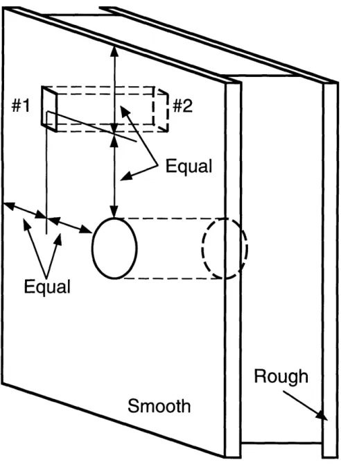
industry for applications in both civilian and military airplanes, missiles, and spacecraft [55]. Their advantages of high bending stiffness and low weight exist because thin composite facesheets are used [56]. The compressive properties of composite laminates can be employed without failure occurring as a result of a global instability, as would be observed in a very slender structure such as a thin laminate by itself. Although part of the intention of using sandwich panels includes avoiding instabilities, several buckling-related behaviors can still occur, such as shear crimping, facesheet wrinkling, and facesheet dimpling [55, 56]. Several possible buckling failure modes are shown in figure 2.2.
One very important issue arises from the literature regarding the compressive response of sandwich structures. A majority of the work focuses on characterizing the damage mechanisms and damage tolerance which arise as a result of post-impact compression. In service, sandwich structures are susceptible to a variety of impact events such as a hailstone strike or a tool drop, which in turn causes damage to the sandwich panel. The present work utilizes circular holes, in one sense, as an idealization of the damage incurred by such impact events. Therefore, failure mechanisms arising from post-impact compression are relevant to this work.
It should be noted that static and dynamic impact tests are performed on specimens to yield a representation of damage that might be incurred in service. Although simplifications exist (e.g. using a hole to represent impact damage) as cost-effective alternatives to actually impacting the specimen, the distinction between the actual case (impact) and the idealized case (hole) based on experimental observations needs to be addressed. It has been shown that impactor size cannot be used as the metric with which to measure hole size, since compressive strengths for impacted carbon/epoxy laminates are less
General Buckling
Shear Crimping
Facesheet Wrinkling
ADHESIVE BOND FAILURE
1111111 111111I11 lII
HONEYCOMB CORE
FACES BUCKLE INTO CORE CELLS
Facesheet Dimpling
Possible instabilities in sandwich structures [56]. Figure 2.2
all-than those with holes of the same diameter of the impactor [57]. The amount of visible damage resulting from impact is also not a reliable metric, since impact events can cause externally invisible sub-surface damage [58, 59]. This fact, along with the difference in failure mechanisms observed in both impacted and notched sandwich panels loaded in compression (as will be discussed later), is important when assessing the overall effectiveness of using notches as representative damage [60]. However, the determination of the effectiveness of notches in accomplishing this task is beyond the scope of this work.
2.3.1 Compressive Damage Mechanisms in Sandwich Panels with Unidirectional Facesheets
Unnotched sandwich panels with [+45/-45/0]s (the layup represents one facesheet, and the sandwich panel is symmetric about its centerline) carbon/epoxy facesheets and various core materials and thicknesses exhibited failure modes that varied with core type [61-63]. All cores were 9.6mm thick or less. Measurements of out-of-plane facesheet displacement during testing indicated that a general buckling instability at least partially contributed to most of the observed failure modes. Panels with aluminum honeycomb cores failed due to facesheet fracture across the width of the specimen. Widespread facesheet debonding characterized by large bulges was the main failure mode in panels with NomexTM cores, although some specimens failed due to facesheet fracture accompanied by delamination. No facesheet damage was found in the majority of specimens with foam cores. Instead, the foam core fractured across its width. Accompanying damage included through-thickness facesheet fracture and delamination.
using a material such as epoxy to mount the ends of the specimen (also known as "potting") to prevent end failures. However, such fixtures can cause stress concentrations and failure modes of their own. For example, potted specimens with twelve ply multidirectional carbon/epoxy quasi-isotropic facesheets surrounding a 19mm thick glass-reinforced phenolic honeycomb core were characterized by a brooming failure near the potting compound, which included facesheet fracture, fiber splitting, and delamination [60]. The same specimens having a center end-rounded slit in either one or both facesheets failed by facesheet fracture. Fiber splitting was also observed to have occurred from the slit tip in the outer ply in the fiber direction.
2.3.2 Compressive Damage Mechanisms in Sandwich Panels with Woven Fiber Facesheets
Unnotched sandwich panels consisting of plain weave carbon/epoxy facesheets in [0/90] or [+45/-45] orientations and NomexTM honeycomb cores were found to exhibit failure modes caused by buckling. Specimens with cores of either 9.5, 17.4, or 25.4mm thickness failed due to facesheet fracture or core failure [64]. Facesheet fracture was not acknowledged as a valid failure mode because it occurred due to the stress concentrations near the ends of the specimens. Buckling of facesheets was observed to occur when facesheets separated from the core material as a result of core tearing. Note that core tearing did not involve damage to the adhesive bond between the facesheet and the core. Sandwich panels also failed due to buckling as a result of core shear failure. This mode was characterized by global shear crippling. Unnotched [0/90] specimens with 25.4mm core thicknesses also exhibited facesheet fracture in combination with core tearing, but buckling was not observed to be the failure mechanism [4]. Facesheet fracture occurred in both facesheets,
but on one side, the core material tore in a location underneath the fracture site. The opposite side showed minimal core damage or none at all. Similar results were found in sandwich panels with [+45/-45] facesheets. The only difference was that facesheet fracture occurred in the fiber angle directions. Both facesheets failed, and the line of fracture was continuous, oriented in either a straight or triangle wave manner.
Different failure mechanisms were observed in notched specimens with 25.4mm thick cores [65]. Specimens had a circular hole in the center of one facesheet. [0/90] specimens suffered facesheet fracture in both facesheets with core tearing accompanying fracture on one side. Sandwich panels with [+45/-45] facesheets fractured along the fiber orientation angles. Through-thickness facesheet damage was not detected, which led to the conclusion that failure began between plies. Core tearing and bulges in both facesheets were also observed, but were not attributed to buckling instabilities because audible damage events along with cracks visible on the surface ply occurred prior to catastrophic failure. Facesheet fracture at a location other than through the hole was also observed.
Unnotched woven Kevlar specimens failed due to facesheet wrinkling, which caused full width facesheet fractures [66]. Facesheet wrinkling was also observed in carbon/epoxy specimens with two to four plies in assorted orientations and various 25.4mm thick honeycomb cores [67]. These findings lead to an important conclusion arising from the literature. The discrepancy which exists in describing failure mechanisms makes it difficult to specify the exact precursor to failure. For example, although facesheet fracture may be the ultimate failure mode, in many cases no information is found as to the damage mechanisms causing fracture. In this case, facesheet wrinkling was found to be the key damage mechanism. Whether or not facesheet fracture or
other damage modes are due to different failure mechanisms or are failure mechanisms in themselves is in many cases not documented in the literature.
2.3.3 Compressive Damage Mechanisms in Impacted Sandwich Structures
As mentioned before, testing of impacted sandwich panels attempts to capture damage modes that would be incurred from in-service impact events. To accomplish this, different fixtures may be used, as well as static or dynamic impact. Plain weave carbon/epoxy facesheets with two ([+45/-45] and [0/901) and three ([0/90/-45]) ply facesheets and various Nomex core thicknesses up to 25.4mm were subjected to static indentation or dynamic impact [64]. Damage occurred as a result of the impact event, and was characterized by a "dimple". Compressive residual strength tests revealed that the key damage mechanism in both indented and impacted specimens was growth of the dimple. The dimple grew in area and length, primarily in a direction perpendicular to the loading direction. Dimple propagation continued until it completely traversed the facesheet, causing catastrophic facesheet fracture. The core tearing that accompanied facesheet fracture was indicative of buckling, since the thickness of the core still connected varied along the facesheet. Therefore, although dimple propagation was the observable damage mechanism (the red herring), facesheet wrinkling was the cause of failure.
Other compressive failure mechanisms were also observed in [0/90] and [+45/-45] plain weave carbon/epoxy specimens [4]. [0/90] panels with initial damage from static indentation or damage from simulated core damage (an initially crushed core) and static indentation had significant transverse dimple propagation prior to ultimate failure. The dimple did not extend across the full width of the damaged facesheet in all cases. When the dimple did cross the
entire facesheet, a full width facesheet fracture was accompanied by core tearing and core crushing, along with distinct facesheet bulges at the location of core tearing. Dimple propagation, facesheet fracture, core tearing, and core crushing were also observed in similarly impacted/damaged [+45/-45] panels. However, panels with simulated facesheet damage (resulting from very narrow cuts made with a Dremel® Moto-Tool®) failed due to stable damage propagation. Facesheet fractures extended from the tips of the slits in a stable manner along the fiber orientation angles. Fracture lines were either straight or oriented in a triangle wave pattern. Ultimate failure occurred instantaneously, with fracture lines extending the full width of the facesheet. Other material systems, such as impacted sandwich panels with woven Kevlar facesheets have exhibited stable dimple growth as well [66].
2.3.4 Compressive Damage Mechanisms in Other Structures
Carbon/PEEK structures in circular rod and ring structures tested in compression failed due to sudden fracture [68]. Rods that had non-uniform cross-sections broke into two pieces upon failure. Rings fractured at one location on a line at a small angle to the loading direction. Circular rods that had uniform cross-sections, however, developed kink bands. Multiple kink bands were observed, and they were found to increase in number with further end-shortening [68, 69].
2.3.5 Summary
Both unnotched and notched composite-honeycomb sandwich panels with either unidirectional tape or woven fiber architectures generally failed due to facesheet fracture. Stable growth of a kink band-dominated damage zone, as reported for thick laminates, was not observed. However, stable growth of an impact-induced dimple did occur. In both cases, increased end shortening

![Figure 4.7 COD comparison of numerical solution (reference [116]) and FEM neglecting tractions for point load on crack face.](https://thumb-eu.123doks.com/thumbv2/123doknet/14428913.514792/103.918.138.711.339.879/figure-comparison-numerical-solution-reference-neglecting-tractions-point.webp)