Publisher’s version / Version de l'éditeur:
Vous avez des questions? Nous pouvons vous aider. Pour communiquer directement avec un auteur, consultez la
première page de la revue dans laquelle son article a été publié afin de trouver ses coordonnées. Si vous n’arrivez pas à les repérer, communiquez avec nous à [email protected].
Questions? Contact the NRC Publications Archive team at
[email protected]. If you wish to email the authors directly, please see the first page of the publication for their contact information.
https://publications-cnrc.canada.ca/fra/droits
L’accès à ce site Web et l’utilisation de son contenu sont assujettis aux conditions présentées dans le site LISEZ CES CONDITIONS ATTENTIVEMENT AVANT D’UTILISER CE SITE WEB.
Internal Report (National Research Council of Canada. Institute for Research in
Construction), 2002-08-01
READ THESE TERMS AND CONDITIONS CAREFULLY BEFORE USING THIS WEBSITE. https://nrc-publications.canada.ca/eng/copyright
NRC Publications Archive Record / Notice des Archives des publications du CNRC :
https://nrc-publications.canada.ca/eng/view/object/?id=04796605-f0cd-4d65-8c98-ff1b51f1cca6 https://publications-cnrc.canada.ca/fra/voir/objet/?id=04796605-f0cd-4d65-8c98-ff1b51f1cca6
NRC Publications Archive
Archives des publications du CNRC
For the publisher’s version, please access the DOI link below./ Pour consulter la version de l’éditeur, utilisez le lien DOI ci-dessous.
https://doi.org/10.4224/20378755
Access and use of this website and the material on it are subject to the Terms and Conditions set forth at
Results of fire resistance tests on full-scale gypsum board wall
assemblies
Results of Fire Resistance Tests on Full-Scale Gypsum Board Wall Assemblies
Sultan, M.A.; Lougheed, G.D.
IR-833
RESULTS OF FIRE RESISTANCE TESTS ON FULL-SCALE GYPSUM BOARD WALL ASSEMBLIES
By M. A. Sultan and G. D. Lougheed
Internal Report No. 833 Date of issue: August 2002
This is an internal report of the Institute for Research in Construction. Although not intended for general distriubution, it may be cited as a refereance in other publications.
2
ACKNOWLEDGMENTS
This research is a Joint Research Project among the following partners. The National Research Council Canada appreciates the participation of these partners in research, both in terms of their financial contributions and in terms of their technical contributions through the Project Steering Committee.
• Canadian Mortgage and Housing Corporation • Canadian Home Builders Association
• Fiberglas Canada Inc. • Roxul Inc.
• Cellulose Insulation Manufacturers Association of Canada • Gypsum Manufacturers of Canada
• Forintek Canada Corporation
• Canadian Sheet Steel Building Institute • Institute for Research in Construction
3
RESULTS OF FIRE RESISTANCE TESTS ON FULL-SCALE GYPSUM BOARD WALL ASSEMBLIES
ABSTRACT
This report presents the results of 22 full-scale fire resistance tests conducted at the National Fire Laboratory on insulated and non-insulated full-scale gypsum board protected wall assemblies. Three assembly arrangements were studied: symmetrical installation 1x1 (one layer of gypsum board on both the exposed and unexposed sides), asymmetrical installation 1x2 (one layer of gypsum board on the exposed side and two layers of gypsum board on the unexposed side), and symmetrical installation 2x2 (two layers of gypsum board on each of the exposed and unexposed sides) on wood and on light weight steel studs. Two gypsum board types, Type X and regular, were
considered. Three 12.7 mm thick regular gypsum boards were evaluated with different masses per unit area: 7.82 kg/m2 with no glass fibre in the gypsum core, 7.35 kg/m2 with glass fibre in the gypsum core and 7.27 kg/m2 with no glass fibre in the gypsum core. The insulations tested were glass, mineral and cellulose (blown dry and wet spray) fibres.
The effects of resilient channel installation, insulation types, types and thicknesses of gypsum board, symmetrical and asymmetrical installation of gypsum board and stud types on the fire resistance rating of wall assemblies were investigated.
The results of these tests showed:
Resilient Channel Effects - In the asymmetrical loadbearing assemblies (1x2) with
mineral fibre insulation and resilient channels, the assembly with resilient channels installed on the double layer side provided a better fire resistance rating than the assembly with resilient channels installed on the single layer side.
Insulation Effect - Glass Fibre - In non-loadbearing (1x2) assemblies, the installation
of the glass fibre insulation in the wall cavity did not affect the fire resistance rating of the assembly compared to a non-insulated assembly.
Insulation Effect - Cellulose Fibre - In non-loadbearing (1x2) assemblies, the
installation of the cellulose fibre insulation (wet sprayed) in the wall cavity did not affect the fire resistance rating of the assembly compared to a non-insulated assembly.
Insulation Effect - Mineral Fibre - In non-loadbearing (1x2) assemblies, the installation
of the mineral fibre insulation in the wall cavity provided a 54% increase in the fire resistance rating compared to a non-insulated assembly.
In non-loadbearing (1x2) assemblies, the width of the mineral fibre insulation batts in the wall cavity played a significant role in the fire resistance rating compared to a non-insulated assembly. An assembly with insulation installed tight between the studs provided a better fire resistance rating (100 min) than an assembly with insulation installed loose (60 min).
4
Effects of Gypsum Board Thickness - In loadbearing (1x2) assemblies with glass fibre
insulation in the wall cavity and resilient channels located on the single layer (fire-exposed side), changing the gypsum board thickness from 12.7 mm to 15.9 mm did not improve the fire resistance rating. The failure was predominantly due to the piloted ignition of the unprotected wood studs in the space created between the resilient channels and the edges of the studs.
Effect of the Number of Gypsum Board Layers on the Exposed Side - In
loadbearing assemblies with glass fibre insulation in the wall cavity and resilient
channels, an assembly with double layer (2x2), 12.7 mm thick, gypsum board provided a 55% increase in the fire resistance ratings compared to an (1x2) assembly with 12.7 mm thick gypsum board.
Fire Resistance Rating of a Single Layer Gypsum Board (1x1) on Steel Studs - A
non-loadbearing (1x1) assembly with 15.9 mm thick Type X gypsum board on steel studs provided a 52 min fire resistance rating.
Fire Resistance Rating of (1x2) Staggered Wood Stud Assembly - A loadbearing
(1x2) assembly with 12.7 mm thick Type X gypsum board with staggered wood studs on a single plate and a layer of 90 mm thick glass fibre insulation on the exposed side provided a 51 min fire resistance rating.
Fire Resistance Rating of (1x1) Double Wood Stud Assembly - A loadbearing (1x1)
assembly with 15.9 mm thick Type X gypsum board and a double row of wood studs on two separate plates provided a 59 min fire resistance rating.
Effect of Glass Fibre In Gypsum Core - In loadbearing assemblies with regular
lightweight gypsum board, the presence of the glass fibre in the gypsum core increased the fire resistance rating of an (1x1) assembly compared to an assembly with no glass fibre in the gypsum core. In an (2x2) assembly, the increase was insignificant.
Effect of Mass/Unit Area of Gypsum Board - In non-loadbearing (2x2) assemblies, an
assembly with a higher mass/unit area regular gypsum board, 7.82 kg/m2
(approximately 1.6 lb/ft2) provided a slightly better fire resistance rating compared to an assembly with lower mass/unit area gypsum board, 7.35 kg/m2 (approximately 1.5 lb/ft2). This effect might be significant in a single layer (1x1) assembly.
Effect of Stud Types - In non-loadbearing (2x2) assemblies, the assemblies with wood
studs provided a slightly better fire resistance rating than assemblies with steel studs.
Correlation of Full- and Small-scale Fire Test results - A good correlation of the fire
resistance rating of full- and small-scale tests was obtained for non-loadbearing assemblies.
5
RESULTS OF FIRE RESISTANCE TESTS ON FULL-SCALE, INSULATED AND NON-INSULATED, GYPSUM BOARD PROTECTED WALL ASSEMBLIES
1.0 INTRODUCTION
A number of recent changes to the 1990 edition of the National Building Code of Canada (NBCC)[1] and to the CAN/CSA-A82.27-M91 Standard "Gypsum Board-Building Materials and Products"[2] may have an effect on the fire performance of insulated and non-insulated gypsum board protected assemblies. One of the major issues is that the requirement for mass per unit area for gypsum board products has been removed. As well, there have been changes in the NBCC to increase the sound transmission ratings from STC 45 to STC 50 between dwelling units. Either or both of these changes may have an impact on the fire resistance of both wall and floor assemblies referenced in Parts 3 and 9 of the NBCC, as well as the calculation methods in Chapter 2 of the Supplement to the NBCC.
As a result of these changes, a Joint Research Project between IRC/NRCC and 8 industry partners was conducted with the primary objective of determining the impact that the various changes to the codes and standards may have had on the fire
resistance ratings of insulated and non-insulated gypsum board protected wall assemblies. To evaluate these possible effects, a number of full-and small-scale fire tests were conducted.
This report presents the results of 22 full-scale fire tests conducted at the National Fire Laboratory, National Research Council Canada, as part of the Joint Research Project to determine the effects of resilient channel installations, type of insulation in the wall cavity, type and thickness of gypsum board, symmetrical and asymmetrical installation of gypsum board and stud types on fire resistance performance of assemblies. The results of the fire performance of the full-scale assemblies are analyzed and presented. The results of the small-scale fire resistance tests are presented in a separate report listed as Reference [3]. Temperature
measurements at various locations in the assemblies are presented in References [4, 5, 6 and 7].
2.0 DESCRIPTION OF TEST ASSEMBLIES
The full-scale test assembly furnace is shown in Figure 1.
2.1 Dimensions
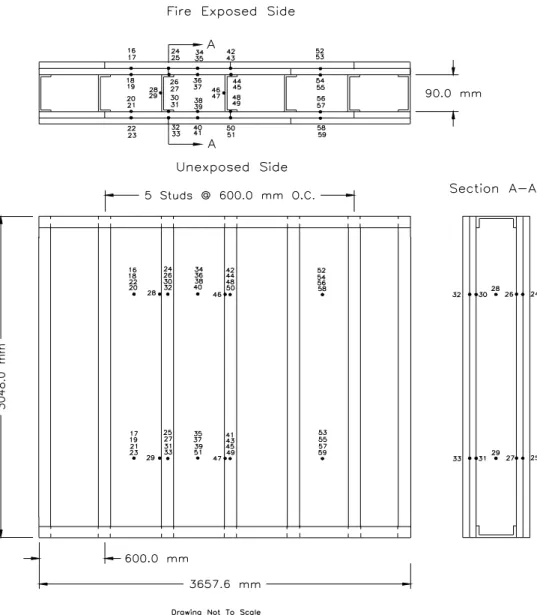
Twenty-two, 3048 mm high by 3658 mm wide, full-scale wall assemblies were constructed. The assemblies had various depths depending on the number of layers of gypsum board. The specific dimensions of each assembly are given in Figures 2 to 23.
2.2 Materials
6
2.2.1 Gypsum Board
Type X and regular gypsum board, conforming to the requirements of CAN/CSA-A82.27-M91 [2], were used. Three different, 12.7 mm thick, regular gypsum board types were evaluated: the first had no glass fibre in the gypsum core with a mass/unit area of 7.82 kg/m2, the second had glass fibre in the gypsum core with a mass/unit area of 7.35 kg/m2 and the third had no glass fibre in the gypsum core with a mass/unit area of 7.27 kg/m2. The thicknesses of Type X gypsum board used in the assemblies were 12.7 mm and 15.9 mm.
2.2.3 Framing Materials
The steel studs used conformed to CGSB CAN/CGSB-7.1 [8] and the wood studs used were nominal 2x4's, (38 mm thick by 89 mm deep) and conformed to CSA 0141-1970 [9].
2.2.4 Resilient Channels
The resilient channels used in the assemblies consisted of sections of 0.46 mm thick galvanized steel. These channels consisted of a 34 mm web and one flattened 18 mm flange lip. The flange between the web and flattened lip was perforated with 36 mm oblong holes.
2.2.5 Insulation
Five types of insulation were used: Glass Fibre-R12 and R13 (Supplied by Fiberglas Canada Inc., Willowdale, Ontario with a mass per unit area of 1.08 kg/m2 and 1.47 kg/m2 , respectively), Mineral Fibre-R13 (Supplied by Roxul Inc., Milton, Ontario with a mass per unit area of 2.78 kg/m2) and Cellulose Fibre (Supplied by Thermo-Cell Insulation Ltd., Orleans, Ontario with a mass per unit area of 4.57 kg/m2 and 5.25 kg/m2 for wood stud and steel stud assemblies, respectively). All of the types of insulation used satisfy CSA A101 [10].
2.3 Fabrication
The full-scale wall assemblies were constructed in accordance to CAN/CSA-A82.31-M91 [11]. All assemblies were constructed by the same contractor using the same construction practices. Details on the assemblies are presented in Table 1. 2.3.1 Wood Stud Assemblies
The wood studs used were 38 mm by 89 mm (SPF No. 1 and No. 2, S-Dry, QLMA Mill Grade 149 supplied by Forintek Canada for all but Assemblies 01 and F-02) spaced at 600 mm O.C. in Assembly F-04 and spaced at 400 mm O.C. in all other wood stud assemblies.
In single layer assemblies (1x1) with wood studs spaced at 400 mm O.C., the gypsum board was attached to the wood studs with Type S drywall screws, 41 mm long, spaced at 400 mm O.C. along the edges and in the field of the board. Screw locations
7
and gypsum board joints are shown in Figures 24 to 25 [11]. Screw heads on both the exposed and unexposed faces were covered with joint compound. Gypsum board joints were also taped and covered with joint compound.
In double layer assemblies (2x2) with wood studs spaced at 400 mm O.C., both the exposed and unexposed sides had two gypsum layers: base and face layers. The base layer was attached to the wood studs with Type S drywall screws, 41 mm long, spaced at 600 mm O.C. in the field of the board and along the edges. The face layer was attached to both the base layer and the studs with Type S drywall screws, 51 mm long, spaced at 400 mm O.C. along the edges and in the field of the board. Screw locations and gypsum board joints are shown in Figures 26 to 29 [11]. Screw heads on both the exposed and unexposed faces were covered with joint compound. Gypsum board joints on the face layers were also taped and covered with joint compound.
In double layer assemblies (2x2) with wood studs spaced at 400 mm O.C. and with resilient channels installed on the exposed side, both the exposed and unexposed sides had two gypsum layers: base and face layers. Eight rows of resilient channels spaced at 400 mm O. C. were attached horizontally, perpendicular to the wood studs on the exposed side, with 25 mm long, self drilling, self tapping steel screws spaced at 300 mm O.C. using similar construction practices to those specified in ULC Assembly U-311 [12].
On the exposed side, the base and face gypsum layers were applied horizontally with one vertical joint 1219 mm long in each layer. The vertical joint in the base layer on the wall cavity side was unbacked. The base layer was attached to the resilient
channels with Type S drywall screws, 25 mm long, spaced at 600 mm O.C. in the field of the board and spaced at 300 mm O. C. along the edges of the board. The face layer was attached to both the base layer and the resilient channels with Type S drywall screws, 41 mm long, spaced at 300 mm O.C. along the edges and in the field of the board. Screw locations and gypsum board joints are shown in Figures 30 and 31 [11].
On the unexposed side, the base and face gypsum layers were applied vertically. The base layer was attached to the wood studs with Type S drywall screws, 41 mm long, spaced at 600 mm O.C. in the field of the board and along the edges. The face layer was attached to both the base layer and the studs with Type S drywall screws, 51 mm long, spaced at 400 mm O.C. along the edges and in the field of the board. Screw locations and gypsum board joints are shown in Figures 32 to 33 [11]. Screw heads on both the exposed and unexposed faces were covered with joint compound. Gypsum board joints on the face layers were also taped and covered with joint compound.
In double layer assemblies (2x2) with wood studs spaced at 600 mm O.C., both the exposed and unexposed sides had two gypsum board layers: base and face layers. The base layer was attached to the wood studs with Type S drywall screws, 41 mm long, spaced at 600 mm O.C. in the field of the board and along the edges. The face layer was attached to both the base layer and the studs with Type S drywall screws, 51 mm long, spaced at 300 mm O.C. along the edges and in the field of the board. Screw locations and gypsum board joints are shown in Figures 34 to 37 [11]. Screw heads on both the exposed and unexposed faces were covered with joint compound. Gypsum board joints, on the face layers, were also taped and covered with joint compound.
8
In asymmetrical installation (1x2) assemblies with wood studs spaced at 400 mm O.C., the exposed side had one gypsum board layer and the unexposed side had two gypsum board layers: base and face layers. The base layer on the unexposed side was attached to the wood studs with Type S drywall screws, 41 mm long, spaced at 600 mm O.C. and in the field of the board and along the edges of the gypsum board. The face layer was attached to both the base layer and wood studs with Type S drywall screws, 51 mm long, spaced at 400 mm O.C. The gypsum board layer on the exposed side was attached to wood studs with Type S drywall screws, 41 mm long, spaced at 400 mm O.C. along the edges of the gypsum board and in the field of the board. Screw
locations and gypsum board joints are shown in Figures 38 to 40 [11]. Screw heads on both the exposed and unexposed faces were covered with joint compound. Gypsum board joints, on the face layer, were also taped and covered with joint compound.
In asymmetrical installation (1x2) assemblies with wood studs spaced at 400 mm O.C. and with resilient channels installed on the exposed side, the exposed side had one gypsum board layer and the unexposed side had two gypsum board layers: base and face layers. Eight rows of resilient channels, spaced at 400 mm O. C., were
attached horizontally, perpendicular to the wood studs, on the exposed side, with 25 mm long, self drilling, self tapping steel screws spaced at 300 mm O.C. using similar
construction practices to those specified in ULC Assembly U-311 [12].
On the exposed side (single gypsum layer), the gypsum layer was applied horizontally with one vertical unbacked joint 1219 mm long. The gypsum board layer was attached to the resilient channels with Type S drywall screws, 25 mm long, spaced at 300 mm O.C. along the edges and in the field of the board. Screw locations and gypsum board joints are shown in Figure 41 [11].
On the unexposed side (double gypsum layer), the base gypsum layer was attached to the wood studs with Type S drywall screws, 41 mm long, spaced at 600 mm O.C. and in the field of the board and along the edges of the gypsum board. The face layer was attached to both the base layer and wood studs with Type S drywall screws, 51 mm long, spaced at 400 mm O.C. Screw locations and gypsum board joints are shown in Figures 42 and 43 [11]. Screw heads on both the exposed and unexposed faces were covered with joint compound. Gypsum board joints, on the face layer, were also taped and covered with joint compound.
In asymmetrical installation (1x2) assemblies with wood studs spaced at 400 mm O.C. and with resilient channels installed on the unexposed side (double gypsum layer), the exposed side had one gypsum board layer and the unexposed side had two gypsum board layers: base and face layers. Eight rows of resilient channels, spaced at 400 mm O.C., were attached horizontally, perpendicular to the wood studs, on the unexposed side, with 25 mm long, self drilling, self tapping steel screws spaced at 300 mm O.C. using similar construction practices to those specified in ULC Assembly U-311 [12].
On the exposed side (single gypsum layer), the gypsum layer was attached to wood studs with Type S drywall screws, 41 mm long, spaced at 400 mm O.C. along the edges of the gypsum board and in the field of the board. Screw locations and gypsum board joints are shown in Figure 44[11].
9
On the unexposed side (double gypsum layer), the base and face gypsum layers were applied horizontally with one vertical joint 1219 mm long in each layer. The vertical joint in the base layer on the wall cavity side was unbacked. The base layer was
attached to the resilient channels with Type S drywall screws, 25 mm long, spaced at 600 mm O.C. in the field of the board and spaced at 300 mm O. C. along the edges of the board. The face layer was attached to both the base layer and the resilient channels with Type S drywall screws, 41 mm long, spaced at 300 mm O.C. along the edges and in the field of the board. Screw locations and gypsum board joints are shown in Figures 45 and 46 [11]. Screw heads on both the exposed and unexposed faces were covered with joint compound. Gypsum board joints, on the face layer, were also taped and covered with joint compound.
2.3.2 Steel Stud Assemblies
The steel studs were light C sections 90 mm by 30 mm by 0.46 mm and were spaced at 600 mm O.C.
In single layer assemblies (1x1) with steel studs spaced at 600 mm O.C., the gypsum board was attached to the steel studs with Type S drywall screws, 25 mm long, spaced at 300 mm O.C. along the edges of the gypsum board and in the field of the board. Screw locations and gypsum board joints are shown in Figures 47 and 48 [11]. Screw heads on both the exposed and unexposed faces were covered with joint compound. Gypsum board joints were also taped and covered with joint compound.
In double layer assemblies (2x2) both the exposed and unexposed sides had two gypsum board layers: base and face layers. The base layer was attached to steel studs with Type S drywall screws, 25 mm long, spaced at 600 mm O.C. in the field of the board and spaced at 300 mm O.C. along the edges of the board. The face layer was attached to both the base layer and steel studs with Type S drywall screws, 41 mm long, spaced at 300 mm O.C. along the edges of the gypsum board and in the field of the board. Screw locations and gypsum board joints are shown in Figures 49 to 52 [11]. Screw heads on both the exposed and unexposed faces were covered with joint
compound. Gypsum board joints on the face layer were also taped and covered with joint compound.
In asymmetrical installation (1x2) assemblies, the exposed side had one gypsum board layer and unexposed side had two gypsum board layers: base and face layers. The base layer on the unexposed side was attached to the steel studs with Type S drywall screws, 25 mm long, spaced at 600 mm O.C. in the field of the gypsum board and spaced at 300 mm O.C. along the edges of the board. The face layer on the unexposed side was attached to both the base layer and the steel studs with Type S drywall screws, 41 mm long, spaced at 300 mm O.C along the edges of the gypsum board and in the field of the board. The gypsum board layer on the exposed side was attached to the steel studs with Type S drywall screws, 25 mm long, spaced at 300 mm O.C. along the edges of the gypsum board and in the field of the board. Screw
locations and gypsum board joints are shown in Figures 53 to 55 [11]. Screw heads on both the exposed and unexposed faces were covered with joint compound. Gypsum board joints were also taped and covered with joint compound.
10
Mineral fibre insulation batts were supplied in sizes 90 mm thick by 615 mm wide for steel stud assemblies and 584 mm wide for wood stud assemblies. All batts were 1220 mm long. The mineral fibre insulation used in Test F-14 was 584 mm wide and did not provide a proper fit between the steel studs. The test was repeated with the 615 mm wide batts (Test F-14B). Glass fibre insulation batts were supplied in sizes 90 mm thick by 615 mm wide for steel stud assemblies and 584 mm wide for wood stud
assemblies by 1220 mm long. The cellulose fibre insulation was extruded into the cavity (blind dry fill in the wood stud assembly and wet spray in the steel stud assembly), after the installation of the thermocouples.
2.4 Instrumentation
Type K (20 gauge) chromel-alumel thermocouples, with a thickness of 0.91 mm, were used for measuring temperatures at a number of locations throughout an
assembly. Inside the cavities, the thermocouples were attached to 6 wire hangers installed midway between the studs and at mid depth of the studs at distances of 1/4 and 3/4 of the height of the wall. By providing tension to the hanger wire, the
thermocouples were positioned flush with the surface of the gypsum board.
Thermocouples located in the interface between the steel and the gypsum board layers and those located between gypsum board layers were taped into position and then the gypsum board was screwed to the stud or the face layer.
In wood stud assemblies, a number of small holes, 12.7 mm diameter, were drilled through the wood studs assemblies at the bottom to allow the thermocouple wiring to exit the assembly.
Thermocouple locations are shown for each assembly in Figures 2 to 23.
2.5 Loadbearing Assemblies
The loading device used in this study is illustrated in Figure 1. Details on this device are presented in Reference [13]. This loading system consisted of two steel frames, located at the top and bottom of the wall assembly. Eight hydraulic jacks were used to provide a vertical load to the top of the wall assembly. The applied live loads used in this study are given in Table 1. These loads were calculated by the Canadian Wood Council, in consultation with the other members of the Partnership Committee. The loads used for Tests F-01 and F-02 were selected by NRC.
3.0 TEST APPARATUS
The tests were carried out by exposing the assemblies to heat in a propane-fired vertical furnace as shown in Figure 1. The furnace was lined with fire brick covered with a 2.5 cm thick ceramic fibre insulation blanket. The assemblies were sealed at the edges against the furnace with ceramic fibre blanket. The furnace temperature was measured by nine, 20 gauge shielded, thermocouples in accordance to CAN/ULC-S101-M89 [14]. The average of the nine thermocouple temperatures was used to control the furnace temperature.
11
4.0 TEST CONDITIONS AND PROCEDURES
4.1 Fire Exposure
The ambient temperature at the start of each test was approximately 22°C. During the test, the wall assembly was exposed to heating on the exposed side, in such a way that the average temperature in the furnace followed, as closely as possible, the CAN/ULC-S101-M89 [14] standard temperature-time curve.
4.2 Failure Criterion
The failure criteria for the full-scale tests were from CAN/ULC-S101-M89 [14]. The assembly was considered to have failed if a single point thermocouple temperature reading on the unexposed face rose above 180 °C or the average temperature of the 9 thermocouples readings under the insulated pads on the unexposed face (see Figure 56) rose 140 °C above the ambient temperature or there was passage of flame or gasses hot enough to ignite cotton waste.
4.3 Recording of Results
The furnace and wall assembly temperatures were recorded at 1 minute intervals using LABTECH NOTEBOOK data acquisition software and a Fluke Helios-I data
acquisition system. In Test F-14, due to a power failure at 63 min, all data up to that time was lost. Temperature measurements are provided in References [4 to 7].
5.0 RESULTS AND DISCUSSION
The results of the 22 full-scale fire resistance tests are summarized in Table 1 in which the single point and average failure times (as defined in ULC S101) are given for each assembly. The effects of different parameters on the fire resistance of loadbearing and non-loadbearing gypsum board protected wall assemblies are discussed below.
5.1 Effects of Different Insulation Types in (1x2) Non-loadbearing Steel Stud Assemblies
The fire resistance ratings of non-loadbearing (1x2) insulated and non-insulated full-scale assemblies, using 12.7 mm thick Type X board and steel studs are shown in Figure 57. For all tests, the side of the wall with the single gypsum board layer was exposed to fire.
Glass Fibre Insulation (GFI) - Tests F-09 (GFI) and F-07 (non-insulated) were carried out to investigate the effect of the installation of glass fibre insulation in a wall cavity. The temperature failure criterion was reached at 65 min for Test F-09 and at 65 min for Test F-07. These results suggest that, in (1x2) assemblies, the 90 mm thick glass fibre insulation in the wall cavity did not affect the fire resistance rating.
Mineral Fibre Insulation (MFI) - Tests F-10B (MFI) and F-07 (non-insulated) were conducted to investigate the effect of installation of mineral fibre insulation in the wall cavity on the fire resistance rating. The temperature failure criterion was reached at 100 min for Test F-10B and at 65 min for Test F-07. These results suggest that, in
12
asymmetrical (1x2) assemblies, the installation of 90 mm thick mineral fibre insulation in the wall cavity provided a 54% increase in the fire resistance rating compared to a non-insulated assembly.
Test F-10 (MFI, 584 mm wide, loose fit) and F-10B (MFI, 615 mm wide, tight fit) were conducted to determine whether the width of the insulation batts has an effect on fire resistance performance. The temperature failure criterion, as shown in Figure 58, was reached at 60 min for Test F-10 and at 100 min for Test F-10B. To maximize the benefit of the insulation on the fire resistance rating, these tests showed that it is important to have insulation installed tight between the studs.
Cellulose Fibre Insulation (CFI) - Tests F-11 (CFI) and F-07 (non-insulated) were conducted to investigate the effect on installation of wet sprayed cellulose fibre insulation (CFI) in the wall cavity on the fire resistance rating. The temperature failure criterion was reached at 62 min for Test F-11 and at 65 min for Test F-07. Therefore, in (1x2) wall assemblies, the addition of 90 mm thick wet sprayed cellulose fibre insulation did not effect the fire resistance rating.
5.2 Effects of Different Insulation Types in (1x2) Loadbearing Wood Stud Assemblies with Resilient Channels on the Single Layer Side (Figure 59)
Tests F-08 (GFI) and F-12 (MFI) were conducted to investigate the effect of different types of insulation in the wall cavity on the fire resistance ratings of loadbearing (1x2) assemblies with resilient channels on the single layer side (fire-exposed side). The structural failure and flame penetration criteria were reached at 51 min in Test F-08 and 52 min in Test F-12. The difference in the fire resistance ratings is within the systematic error of the test procedure. The failure is predominantly due to the early piloted ignition of the unprotected wood stud in the space between the gypsum board and the edge of the studs created by the installation of the resilient channels. The wood studs started to burn at the same time for both tests. Because these were loadbearing assemblies, the eventual reduction of the wood cross section resulted in structural failure of the assemblies. These results showed that, in (1x2) assemblies with resilient channels installed on the single layer exposed side, the insulation type did not affect the fire resistance ratings.
5.3 Effects of Different Insulation Types in (1x2) Loadbearing Wood Stud Wall Assemblies with Resilient Channels on the Double Layer Side (Figure 60)
Tests F-13 (CFI, dry blown) and F-17 (MFI) were conducted to investigate the effect of the type of insulation, in the wall cavity on the fire resistance ratings of loadbearing (1x2) assemblies with resilient channels on the double layer (unexposed) side. The structural failure and flame penetration criteria were reached at 56 min in Test F-13 and 58 min in Test F-17. These results showed that, in (1x2) wall assemblies with resilient channels installed on the double layer side, the assembly with MFI provided a slightly better fire resistance rating than the assembly with CFI.
5.4 Effect of Resilient Channel Location in Loadbearing Wood Stud Insulated Assemblies (Figure 61)
13
Tests F-12 (resilient channels on the fire-exposed side) and F-17 (resilient channels on the unexposed side) were conducted to investigate whether the location of the resilient channel had an effect on the fire resistance performance of loadbearing (1x2) assemblies using mineral fibre insulation in the wall cavity. The structural failure and flame penetration criteria were reached at 52 min for Test F-12 and at 58 min for Test F-17. These results showed that, the location of resilient channels played an important role in the fire resistance rating. In asymmetrical assemblies (1x2) with mineral fibre insulation, the assembly with resilient channels installed on the double layer side provided an 11% better fire resistance rating than the assembly with resilient channels installed on the single layer side.
5.5 Effects of Gypsum Board Thicknesses in (1x2) Wood Stud Assemblies with Resilient Channels on the Single Layer Side (Fire-Exposed Side) (Figure 62)
Tests F-08 (12.7 mm thick Type X gypsum board), F-14 and F-14B (15.9 mm thick Type X gypsum board) were conducted to investigate the effect of the gypsum board thickness on the fire resistance ratings of loadbearing wood stud gypsum board protected wall assemblies using 90 mm thick glass fibre insulation in the wall cavity, and resilient channels on the single layer side (fire-exposed side). Test F-14B is a repeat of Test F-14 and was conducted to confirm the results. The structural failure and flame penetration criteria were reached at 51 min for Test F-08, at 52 min for Test F-14 and at 51 min for Test F-14B. The difference in the fire resistance ratings is considered to be within the systematic error of the test procedure. The failure is predominantly due to the pilot ignition of the unprotected wood stud edges in the space created by the thickness of the resilient channels on the exposed side. The unprotected wood studs start to burn as the gypsum board joints open. The joint opening occurred at the same time for both gypsum board thicknesses resulting in eventual structural failure of the assembly. These results showed that, in (1x2) Type X gypsum board wall assemblies with the resilient channels installed on the single layer side (fire-exposed side), the thickness of the gypsum board did not play a role in the fire resistance ratings.
Test F-12 with MFI in the wall cavity failed at the same time as the tests with GFI (Figure 62). This suggests that the gypsum board joints are the dominant factor in the failure of the (1x2) loadbearing wall assemblies with resilient channels on the fire exposed side.
5.6 Effects of Number of Gypsum Board Layers on Fire Exposed Side in Wood Stud Assemblies with Resilient Channels (Figure 63)
Tests F-08 (1x2) and F-18 (2x2) were conducted to investigate the effect of the number of gypsum board layers on the fire-exposed side on the fire resistance ratings. The structural failure and flame penetration criteria were reached at 51 min for Test F-08 and at 79 min for Test F-18. These results showed that, the second layer of gypsum board on the fire-exposed side (with staggered joints) provided a 55% increase in the fire resistance rating compared to an assembly with a single layer on the exposed side.
14
Test F-06 was conducted to determine the fire resistance rating of a
non-loadbearing steel stud (1x1) gypsum board protected assembly with 15.9 mm thick Type X gypsum board. The temperature failure criterion was reached at 52 min. This test did not provide the one hour fire resistance rating specified by CAN/CSA-A82.27-M91[2].
5.8 Fire Resistance Rating of a Loadbearing Wall Assembly with Two Rows of Staggered Wood Studs on a Single Plate
Test F-15 was conducted to determine the fire resistance rating of a loadbearing (1x2) 12.7 mm thick, Type X 12.7 mm thick gypsum board protected assembly using staggered wood studs on a single plate. The GFI was placed in the wall cavity on the fire-exposed side (Figure 20). The structural failure and flame penetration criteria were reached at 51 min.
5.9 Fire Resistance Rating of a Loadbearing (1x1) Assembly with Two Rows of Wood Studs on Separate Plates
Test F-16 was conducted to determine the fire resistance rating of a loadbearing (1x1) Type X 15.9 mm thick gypsum board protected wall assembly using two rows of wood studs on separate plates. GFI was placed in the wall cavity on the fire exposed side (Figure 21). The structural failure and flame penetration criteria were reached at 59 min.
5.10 Effects of Glass Fibre in the Gypsum Core of Regular Lightweight Gypsum Board Wall Assemblies (Figures 64 and 65)
Two gypsum board protected wall assembly arrangements were studied: (1x1) with one layer of gypsum board on each of the exposed and unexposed sides and (2x2) with two layers of gypsum board on each of the exposed and unexposed sides.
(1x1) Assemblies - Tests F-01 and F-01B (Figures 2 and 3) were carried out to investigate the effect of the presence of glass fibre in the gypsum core on the fire resistance rating of 1x1 gypsum board wall assemblies using a lightweight regular gypsum board. The structural failure and flame penetration criteria were reached at 33 min for Test F-01 (with glass fibre in the gypsum board core 7.35 kg/m²) and at 26 min for Test F-01B (without glass fibre in the gypsum core 7.27 kg/m²). These results showed that, Assembly F-01 provided a 27% increase in fire resistance compared to Assembly F-01B. Therefore, the presence of glass fibre in regular lightweight gypsum board core did have an effect on the fire resistance performance.
Double Gypsum Layer (2x2) Assemblies - Test F-02 and Test F-02B (Figures 4 and 5) were conducted to investigate the effect of the presence of glass fibre in the gypsum board core on the fire resistance ratings of (2x2) gypsum board wall assemblies using a lightweight regular gypsum board. The structural failure and flame penetration criteria were reached at 53 min for Test F-02 (with glass fibre in the gypsum board core 7.35 kg/m²) and at 49 min for Test F-02B (without glass fibre in gypsum board core 7.27 kg/m²). The presence of glass fibre in regular lightweight gypsum board core did result in a small increase in the fire resistance rating of double layer wall assemblies.
15
5.11 Effects of Different Mass/Unit Area of Regular Gypsum Board Assemblies on Steel Studs (Figure 66)
Test F-03 (lightweight regular gypsum board with glass fibre in the gypsum core, 7.35 kg/m²) and Test F-05 (regular gypsum board with no glass fibre in gypsum core, 7.82 kg/m²) were conducted to investigate whether the reduction in the mass per unit area of gypsum board had an effect on the fire resistance ratings of 2x2 assemblies. The temperature failure criterion was reached at 63 min for Test F-03 and at 69 min for Test F-05. These results showed that, in double layer non-loadbearing steel stud assemblies, the heavier gypsum board provided a slightly better (10%) fire resistance performance compared to the assembly with lightweight gypsum board.
5.12 Effects of Different Stud Types in Non-Loadbearing Regular Lightweight Gypsum wallboard Assemblies (Figure 57)
Test F-03 and Test F-04 were conducted to investigate the effect of stud type (wood and steel) on the fire resistance ratings of double layer (2x2) gypsum board wall assemblies using a lightweight regular (7.35 kg/m²) gypsum board with glass fibre in the gypsum core. The temperature failure criterion was reached at 63 min for Test F-03 (steel studs) and at 65 min for Test F-04 (wood studs). These results showed that, within the systematic error of the test method, in double layer non-loadbearing gypsum board wall assemblies, the type of studs was insignificant.
5.13 Correlation Between the Fire Resistance of the Small- and Full-scale Tests
In this study, 22 full-scale and 49 scale tests were conducted. The small-scale wall assemblies were constructed using similar construction practices to those employed for the full-scale fire tests. The fire resistance ratings of non-loadbearing small-scale tests and loadbearing and non-loadbearing full-scale tests are plotted in Figure 68 to determine whether a correlation between the test results exists. Two correlations between the full-scale and small-scale fire resistance ratings are shown in Figure 68. These are:
non-loadbearing
Full-Scale Fire Resistance Rating = 0.7 Small-Scale Fire Resistance Rating loadbearing
Full-Scale Fire Resistance Rating = 0.6 Small-Scale Fire Resistance Rating The majority of the non-loadbearing results fall between the two extremes (Tests F-10B and Test F-11) and the 0.7 factor would provide a conservative estimate for the full-scale tests without loading. For loadbearing assemblies, the results fall between the two extremes (Tests NRC2 and F-12) and the 0.6 factor would provide a conservative estimate.
6.0 CONCLUSIONS
1. In non-loadbearing (1x2) assemblies, the installation of 90 mm thick glass or cellulose (wet sprayed) fibre insulation in the wall cavity did not affect the fire resistance rating compared to a non-insulated assembly. The installation of 90 mm thick mineral fibre insulation provided a 54% increase in the fire resistance rating.
16
2. Insulation width between the studs in the wall cavity played a significant role in the fire resistance rating. An assembly with insulation installed tight between the studs provided a significantly better fire resistance rating compared to an assembly with insulation installed with gaps between the edges of the insulation and the studs. 3. In loadbearing (1x2) assemblies with resilient channels on the single layer (exposed)
gypsum board side, the assembly with glass fibre insulation provided a similar fire resistance rating to an assembly with mineral fibre insulation.
4. In loadbearing (1x2) assemblies with resilient channels on the double layer
(unexposed)gypsum board side, the assembly with mineral fibre insulation provided a slightly better fire resistance rating than an assembly with cellulose fibre insulation (blown dry).
5. In loadbearing (1x2) assemblies with mineral fibre insulation and resilient channels the assembly with resilient channels on the side with two layers of gypsum board (unexposed) provided a better fire resistance rating than the assembly with resilient channels on the side with a single layer of gypsum board.
6. In loadbearing (1x2) assemblies with glass fibre insulation and resilient channels on the single layer gypsum board side, the increase in the gypsum board thickness from 12.7 mm to 15.9 mm did not provide a significant increase in the fire resistance rating; the presence of the resilient channels on the single layer side significantly affected the fire resistance performance of the assembly.
7. In loadbearing assemblies (1x2) and (2x2) with glass fibre insulation in the wall cavity and resilient channels, the assembly with double layer (2x2), 12.7 mm thick, gypsum board provided a 55% increase in the fire resistance rating compared to an asymmetrical (1x2) assembly with the resilient channels on the side with the single gypsum board layer.
8. A non-loadbearing (1x1) assembly with 15.9 mm thick Type X gypsum on steel studs provided a 52 min fire resistance rating.
9. A loadbearing (1x2) assembly with 12.7 mm thick Type X gypsum board on a staggered wood studs on a single plate and woven glass fibre insulation provided a 51 min fire resistance rating.
10. A loadbearing (1x1) assembly with 15.9 mm thick Type X gypsum board on double wood studs on separate plates provided a 59 min fire resistance rating.
11. The presence of glass fibre in regular lightweight gypsum board cores increased the fire resistance ratings of single layer (1x1) loadbearing assemblies.
12. The presence of glass fibre in regular lightweight gypsum board did not affect the fire resistance ratings of double layer (2x2) loadbearing assemblies.
13. (2x2) assemblies with higher density regular gypsum board (7.82 kg/m2) provided a better fire resistance rating compared to an assembly with lightweight gypsum boards (7.35 kg/m2).
14. In non-loadbearing (2x2) assemblies, the assembly with wood studs provided a slightly better fire resistance performance than an assembly with steel studs.
15. In non-loadbearing assemblies, the fire resistance ratings obtained using small-scale tests correlate well with results obtained with full-scale tests.
17
7.0 REFERENCES
1. National Building Code of Canada (Part 9), National Research Council Canada, Ottawa 1990
2. CAN/CSA-A82.27-M91, Gypsum Board-Building Materials and Products. Canadian Standards Association, Rexdale, Ontario, 1991
3. M.A. Sultan and G.D. Lougheed, Results of Fire Resistance Tests on Small-scale Insulated and Non-insulated Gypsum Board Protected Wall Assemblies, IRC Client Reports No. A4049.S1, A4065.S1, A4050.S1, A4057.S1, A4051.S1 and A4064.S1, 1994
4. M.A. Sultan, G.D. Lougheed and E.M.A. Denham, Temperature Measurements in Fire Resistance Tests on Small-scale Gypsum Board Protected Wall Assemblies with and without Resilient Channels, to be published in IRC Internal Report, 1994 5. M.A. Sultan, G.D. Lougheed, J.W. MacLaurin and E.M.A. Denham, Temperature
Measurements in Fire Resistance Tests on Insulated and Non-insulated Small-scale Type X Gypsum Board Protected Wall Assemblies, to be published in IRC Internal Report, 1994
6. M.A. Sultan, R.C. Monette, E.D.A Denham and D.W. Morwick, Temperature
Measurements in Fire Resistance Tests on Insulated and Non-insulated small-scale Regular Gypsum board wall Assemblies, to be published in IRC Internal Report, 1994
7. M.A. Sultan, J.W. MacLaurin, R.C. Monette and D.W. Morwick, Temperature Measurements in Fire Resistance tests on Small-scale Assemblies of Different Cavity Size, Stud Type and Asymmetrical Installation of Gypsum Board, to be published in IRC Internal Report 1994
8. CAN/CGSB-7.1-M86, Cold Formed Steel Framing Components. Canadian General Standards Board, Ottawa, Ontario, 1986
9. CSA 0141-1970, Softwood Lumber, Canadian Standards Association, Rexdale, Ontario, 1970
10. CSA-A101-M83, Thermal Insulation, Canadian Standards Association, Rexdale, Ontario, 1983
11. CAN/CSA-A82.31-M91, Gypsum Board Application, Canadian Standards Association, Rexdale, Ontario, 1991
12. ULC List of Equipment and Materials, Vol. 3, Fire Resistance Ratings. Underwriters' Laboratories on Canada, 1991 (P272)
13. Shorter, G. W. and Harmathy, T. Z., "Fire Research Furnaces at the National Research Council, Fire Study No.1, Division of Building Research, National Research Council Canada, NRC5732, 1960
14. CAN/ULC-S101-M89, Standard Methods of Fire Endurance Tests of Building Construction and Materials. Underwriters' Laboratories of Canada,
Table 1. Full-Scale Assembly Parameters and Fire Test Results
Assembly Stud Type Stud Size Stud Stud Spacing Gypsum Board Gypsum Board Gypsum Board Insulation Insulation Resilient Applied Fire Mode
Number (mm) Rows (mm) Layers Thickness Type Type Thickness Channel Load Ratin
g
Of
(Exp/Unexp.) (mm) (mm) (kN) (min) Failure
F-01 Wood 89 1 400 1x1 12.7 RL *** *** *** 74.76 33 S/F F-01B Wood 89 1 400 1x1 12.7 RL* *** *** *** 68.83 26 S/F F-02 Wood 89 1 400 2x2 12.7 RL *** *** *** 74.76 53 S/F F-02B Wood 89 1 400 2x2 12.7 RL* *** *** *** 67.22 49 S/F F-03 Steel 90 1 600 2x2 12.7 RL *** *** *** ** 63 Temp. F-04 Wood 89 1 600 2x2 12.7 RL *** *** *** ** 65 Temp. F-05 Steel 90 1 600 2x2 12.7 RH *** *** *** ** 69 Temp. F-06 Steel 90 1 600 1x1 15.9 X *** *** *** ** 52 Temp. F-07 Steel 90 1 600 1x2 12.7 X *** *** *** ** 65 Temp. F-08 Wood 89 1 400 1x2 12.7 X GFI 89 E 67.55 51 S/F
F-09 Steel 90 1 600 1x2 12.7 X GFI 90 *** ** 65 Temp.
F-10 Steel 90 1 600 1x2 12.7 X MFI* 90 *** ** 60 Temp.
F-10B Steel 90 1 600 1x2 12.7 X MFI** 90 *** ** 100 Temp.
F-11 Steel 90 1 600 1x2 12.7 X CFI* 90 *** ** 62 Temp.
F-12 Wood 89 1 400 1x2 12.7 X MFI 89 E 67.55 52 S/F F-13 Wood 89 1 400 1x2 12.7 X CFI 89 U 67.55 56 S/F F-14 Wood 89 1 400 1x2 15.9 X GFI 89 E 66.70 52 S/F F-14B Wood 89 1 400 1x2 15.9 X GFI 89 E 66.70 51 S/F F-15 Wood 89 2* 400 1x2 12.7 X GFI* 89 *** 143.42 51 S/F F-16 Wood 89 2** 400 1x1 15.9 X GFI* 89 *** 143.42 59 S/F F-17 Wood 89 1 400 1x2 12.7 X MFI 89 U 67.55 58 S/F F-18 Wood 89 1 400 2x2 12.7 X GFI* 89 E 66.59 79 S/F
S/F - Structural Failure and Flame Penetration
RL - Low Density Regular Gypsum Board (7.35 kg/m²) RH - Regular Gypsum Board (7.82 kg/m²)
X - Type X
RL* - Low Density Regular Gypsum Board no Glass Fibre in Gypsum Core (7.27 kg/m²)
GFI - Glass Fibre Insulation (R12) GFI* - Glass Fibre Insulation (R13)
CFI - Cellulosic Fibre Insulation (Blown Dry) CFI* - Cellulosic Fibre Insulation (Wet Sprayed) MFI - Mineral Fibre Insulation
MFI* - Mineral Fibre Insulation, 584 mm (23') wide batts, MFI** - Mineral Fibre Insulation, 615 mm (24.25') wide batts
E - Exposed Side U - Unexposed Side
2* - Two rows staggered wood studs, single plate 2** - Two rows wood studs on separate plates *** - Null
Value
Table 2. Loads for Loadbearing Tests
Assembly Total Load Load/Jack
Number
(kN)
(kN)
F-01
74.76
9.34
F-1B
68.83
8.60
F-02
74.76
9.34
F-2B
67.22
8.40
F-08
67.55
8.44
F-12
67.55
8.44
F-13
67.55
8.44
F-14
66.70
8.33
F-14B
66.70
8.33
F-15
143.42
17.93
F-16
143.42
17.93
F-17
67.55
8.44
F-18
66.59
8.32
22
23
24
25
26
27
28
29
30
31
32
33
34
35
36
37
38
39
40
41
42
43
44
Figure 24. Screw Locations For Wood Sud, 1x1 Gypsum Board Layers, Full-Scale assembly (Fire Exposed Side)
45
Figure 25. Screw Locations For Wood Stud, 1x1 Gypsum Board Layers, Full-Scale Assembly (Unexposed Side)
46
Figure 26. Screw Locations For Wood Stud, 2x2 Gypsum Board Layers, Full Scale Assembly ( Base Layer, Fire Exposed Side)
47
Figure 27. Screw Locations For Wood Stud, 2x2 Gypsum Board Layers, Full-Scale Assembly (Face Layer, Fire Exposed Side)
48
Figure 28. Screw Locations For Wood Stud, 2x2 Gypsum Board Layers, Full-Scale Assebly (Base Layer, Unexposed Side)
49
Figure 29. Screw Locations For Wood Stud, 2x2 Gypsum Board Layers, Full-Scale Assembly (Face Layer, Unexposed Side)
52
Figure 32. Screw Locations For Wood Stud, 2x2 Gypsum Board Layers, Full-Scale Assembly, Resilient Channel on Exposed Side (Base Layer Unexposed Side)
54
Figure 34. Screw Locatios For Wood Stud (600 mm O.C.),2x2 Gypsum Board Layers, Full-Scale Assembly (Face Layer, Fire Exposed Side)
55
Figure 35. Screw Locations For Wood Stud (600 mm O.C.),2x2 Gypsum Board Layers, Full-Scale Assembly (Base Layer, Fire Eposed Side)
56
Figure 36. Screw Locations For Wood Stud (600 mm O.C.),2x2 Gypsum Board Layers, Full-Scale Assembly (Base Layer, Unexposed Side)
57
Figure 37. Screw Locations For Wood Stud (600 mm O.C.), 2x2 Gypsum Board
Layers, Full-Scale Assembly (Face Layer, Unexposed Side)
58
Figure 38. Screw Locations for wood Stud, 1x2 Gypsum Board Layers,
Full-Scale Assembly (Base Layer, Fire Exposed Side)
59
Figure 39. Screw Locations For Wood Stud, 1x2 Gypsum Board Layers, Full-Scale Assembly ( Base Layer, Unexposed side)
60
Figure 40. Screw Locations For Wood Stud, 1x2 Gypsum Board Layers, Full-Scale Assembly (Face Layer, Unexposed Side)
62
Figure 42. Screw Locations For Wood Stud, 1x2 Gypsum Board Layers, Full-Scale Assembly, Resilient Channel on Exposed Side (Base Layer Unexposed Side)
67
Figure 47. Screw Locations for Steel Stud, 1x1 Gypsum Board Layers, Full-Scale Assembly (Exposed Side)
68
Figure 48. Screw Locations For Steel Stud,1x1 Gypsum Board Layers, Full-Scale Assembly (Unexposed Side)
69
Figure 49. Screw Locations For Steel Stud, 2x2 Gypsum Board layers, Full-Scale Assembly (Base Layer,Exposed Side)
70
Figure 50. Screw Locations Steel Stud, 2x2 Gypsum Board Layers, Full-Scale Assembly (Face Layer, Exposed Side)
71
Figure 51. Screw Locations For Steel Stud, 2x2 Gypsum Board Layers, Full-Scale Assembly (Base Layer, Unexposed Side)
72
Figure 52. Screw Locations For Steel Stud, 2x2 Gypsum Board Layers, Full-Scale Assembly (Face Layer, Unexposed Side)
73
Figure 53. Screw Locations For Steel Stud, 1x2 Gypsum Board Layers, Full-Scale Assembly (Face Layer, Fire Exposed Side)
74
Figure 54.Screw Locations For Steel Stud, 1x2 Gypsum Board Layers, Full Assembly (Base Layer Unexposed Side)
75
Figure 55. Screw Locations For Steel Stud, 1x2 Gypsum Board Layers, Full-Scale Assembly (Face Layer Unexposed Side)
76
Figure 56. Thermocouple Locations on Unexposed Surface Full-Scale Tests