READ THESE TERMS AND CONDITIONS CAREFULLY BEFORE USING THIS WEBSITE. https://nrc-publications.canada.ca/eng/copyright
Vous avez des questions? Nous pouvons vous aider. Pour communiquer directement avec un auteur, consultez la première page de la revue dans laquelle son article a été publié afin de trouver ses coordonnées. Si vous n’arrivez pas à les repérer, communiquez avec nous à PublicationsArchive-ArchivesPublications@nrc-cnrc.gc.ca.
Questions? Contact the NRC Publications Archive team at
PublicationsArchive-ArchivesPublications@nrc-cnrc.gc.ca. If you wish to email the authors directly, please see the first page of the publication for their contact information.
NRC Publications Archive
Archives des publications du CNRC
This publication could be one of several versions: author’s original, accepted manuscript or the publisher’s version. / La version de cette publication peut être l’une des suivantes : la version prépublication de l’auteur, la version acceptée du manuscrit ou la version de l’éditeur.
Access and use of this website and the material on it are subject to the Terms and Conditions set forth at
Prediction model of optical characteristics for barrel vault skylights
Laouadi, A.; Atif, M. R.
https://publications-cnrc.canada.ca/fra/droits
L’accès à ce site Web et l’utilisation de son contenu sont assujettis aux conditions présentées dans le site LISEZ CES CONDITIONS ATTENTIVEMENT AVANT D’UTILISER CE SITE WEB.
NRC Publications Record / Notice d'Archives des publications de CNRC:
https://nrc-publications.canada.ca/eng/view/object/?id=34dd05b7-36e9-4897-af9e-57116db9891c https://publications-cnrc.canada.ca/fra/voir/objet/?id=34dd05b7-36e9-4897-af9e-57116db9891cPrediction model of optical characteristics for barrel
vault skylights
Laouadi, A.; Atif, M.R.
A version of this paper is published in / Une version de ce document se trouve dans : IESNA 2001 Conference, Ottawa, Ontario, August 5-8, 2001, pp. 241-260
www.nrc.ca/irc/ircpubs
PREDICTION MODEL OF OPTICAL CHARACTERISTICS FOR BARREL VAULT
SKYLIGHTS
Abdelaziz Laouadi and Morad R. Atif
Indoor Environment Research Program, Institute for Research in Construction,
National Research Council of Canada, 1200 Montreal Road, Ottawa, Ontario, Canada, K1A 0R6 Emails: aziz.laouadi@nrc.ca; morad.atif@nrc.ca
ABSTRACT
The topic of this paper is part of a project to develop software to analyze the optical characteristics and daylighting performance of conventional and tubular skylights. Skylights are found in many building types, such as commercial and institutional buildings, houses, shopping malls, hotels, etc. However, skylight manufacturers lack design tools to predict the optical performance of skylight products. Prediction of skylight optical characteristics is a difficult task, due to the complexity of skylight shapes that change with design requirements. This paper presents an analytical model to compute the overall optical characteristics of barrel vault skylights under direct beam light. The model is based on a ray-tracing technique, and can handle skylights with different glazing types (gables opaque, or glazed with different glazing types from the top surface of the skylight), different shapes (short/long with high/low-rise profiles) and different orientation (north-south, west-east, or any direction). Applications of the model showed that barrel vault skylights transmit much more light at high incidence angle on a horizontal surface than similar flat skylights. The skylight length-to-radius ratio (L/R) has a significant impact on the optical characteristics. Short skylights (L/R = 2) with uniform glazing transmit approximately the same amount of light at any sun position. However, long skylights (L/R = 5) transmit about 64% more light when the sun is perpendicular to the skylight axis than when the sun is parallel to the skylight axis. Short skylights with clear gables and tinted top transmit substantially more light than flat skylights with similar tinted glazing, particularly when the sun is parallel to the skylight axis.
INTRODUCTION
The topic of this paper is part of a project to develop software to analyze the optical characteristics and daylighting performance of conventional and tubular skylights. Skylights are found in many modern or retrofitted building types. In commercial and institutional buildings, architectural skylights are used to simulate the outdoors and to bring natural light and solar heat into the indoor space. In residential buildings and houses, conventional skylights are used mainly for illumination. Skylights have the inherent potential to save electrical lighting, cooling and heating energy, beside their positive effects on building occupants satisfaction (HMG 2001, 1999; Heschong and McHugh 2000; Allen 1997; AAMA 1987, 1981; Cassidy 1986; Treado et al. 1983; Jensen 1983). However, despite these amenities, skylights integrated in building design
may result in high-energy consumption if not properly designed. Skylight manufacturers lack design tools to assess the optical and daylighting performance of skylight products due to complex skylight shapes that change with design requirements, and large sizes that impede fitting skylight products into measurement facilities. Furthermore, while measurements on some skylight products are possible, they can not be generalized for other products. In addition, fenestration simulation computer programs such as VISION4 (CANMET 1995) and WINDOW4.0 (LBL 1992) deal with only planar geometry, such as windows and flat skylights.
In this paper, an analytical model is developed to predict the overall optical characteristics of barrel vault skylights under direct sunlight. The specific objectives are:
1. To predict the overall optical characteristics (transmittance, absorptance and reflectance) of barrel vault skylights under direct beam light;
2. To apply the model to investigate the effects of skylight dimensions, orientation and surface glazing types on the skylight transmittance; and
3. To apply the model to predict the effect of the skylight orientation on the daily profile of the skylight transmittance.
MATHEMATICAL FORMULATION
A barrel vault skylight is a glazed cylindrical surface, defined by its truncation angle (σ0), radius (R) and length (L). The gables (end walls) of the skylight may also be glazed with different glazing types from that of the cylindrical part. The skylight is oriented with an azimuth angle ψ0 with respect to the south direction. Figure 1 shows a schematic description of a barrel vault skylight.
The light flux incident on a barrel vault skylight depends on its geometry, orientation with respect to the south direction, and inclination with respect to the horizontal. Optical characteristics of transparent surfaces (transmittance, absorptance, and
reflectance) are available only for planar surfaces (ASHRAE, 1997; IESNA, 2000). Optical characteristics of barrel vault surfaces can be evaluated based on their geometry and the optical characteristics of the flat sheets they are made of. Using a ray-tracing technique, a barrel vault surface can be divided into a number of elemental inclined planar surfaces. The light flux incident on the barrel vault surface may, thus, be readily
x z y σ0 L R ψ 0 south direction gable top surface
calculated by summing up all light fluxes incident on the inclined elemental surfaces. The transmitted light flux through the barrel vault surface may be calculated by summing up all the transmitted light fluxes through the inclined elemental surfaces that reach the skylight base surface. Therefore, transmittance of the barrel vault surface can be obtained. Other optical characteristics, such as absorptance or reflectance, can be obtained in a similar manner. This ray-tracing technique was originally applied to predict the optical characteristics of domed skylights (Laouadi and Atif 1998, 1999, and 2000).
In this paper, an analytical model based on the ray-tracing technique is developed to predict the overall optical characteristics of barrel vault skylights under direct beam light. The analytical modeling seeks to find mathematically well-defined surfaces exposed to the sun’s rays as they pass through the skylight geometry. In this regard, two positions of the sun with respect to the skylight position are identified: sun parallel and perpendicular to the skylight axis. When the sun is in between the two positions, an interpolation formula is used. The model uses the following assumptions:
1. Skylight surfaces are transparent and specular.
2. The beam light transmittance, absorptance and reflectance at any point on the skylight surface are equal to those of a flat surface at the same incidence angle.
3. The amount of light reflection from the interior space under the skylight back to the skylight interior surface is not accounted for.
SUN PARALLEL TO THE SKYLIGHT AXIS
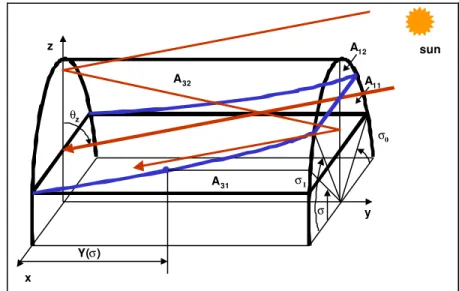
Figure 2 shows a schematic description of the beam light transmission process when the sun is parallel to the skylight axis (y). The skylight
surfaces are designated as A1 and A2 for the gable surfaces (end walls) and A3 for the cylindrical surface. In tracing the beam light transmission, the individual skylight surfaces are split into two portions: one portion corresponds to the directly-transmitted component that reaches the skylight base surface, and the other portion corresponds to the transmitted-reflected component. Skylight surfaces A1 and A3 are completely exposed to the direct beam light. x z y A11 A32 A31 σ1 A12 Y(σ) σ0 θz sun σ
The incident beam light flux on a horizontal skylight is given by the following equation: ds cos E ds cos E Q 3 1 A b A b par =
∫
θ⋅ +∫
θ⋅ (1) where:Eb : beam illuminance (lux); ds : elemental surface (m2);
Qpar : incident flux for the parallel configuration (lumens); and θ : incidence angle on the elemental surface ds (radians).
Figure 3 shows the coordinates of the elemental surface (ds) belonging to the surface A1, A2, or A3. The incidence angle on an inclined surface is given by the following equation (Duffie and Beckman 1991):
) cos( sin sin cos cos cosθ= θz⋅ β+ θz⋅ β⋅ ψs−ψ (2) where:
β : surface inclination angle from the horizontal (varies from 0 to π/2 radians);
θz : sun zenith angle, or the incidence angle on a horizontal surface, (varies from 0 to π/2 radians);
ψ : surface azimuth angle, positive west of south and negative east of south (varies from -π to π radians); and
ψs : solar azimuth angle (varies from -π to π radians). The skylight surfaces A1 (or A2) and A3 are defined as follows:
{
; /2; 0}
: A1 σ0≤σ≤π−σ0 β=π ψ−ψs = (3){
0 y L; ; /2 ; /2}
: A3 ≤ ≤ σ0≤σ≤π−σ0 β= π −σ ψ−ψs=±π (4)where σ is the position angle of a point on the skylight surface A3.
Assuming that the beam illuminance (Eb) is independent of the surface inclination and azimuth angles, equation (1) reduces to:
cos cos E R L 2 S sin E Qpar = b θz⋅ 1+ ⋅ ⋅ b θz σ0 (5) where: L : skylight length (m); R : skylight radius (m);
S1 : area of the surface A1 (m2); and
σ0 : skylight truncation angle (varies from 0 to π/2 radians).
z d y σ ds=Rdσdy ds=R2cos2σ dσ dσ θ
Figure 3 Coordinates of the elemental surface (ds)
The transmitted and absorbed beam fluxes are given by the following equations: ds cos ) 2 / ( ) 2 / ( ) ( E ds cos ) 2 / ( ) 2 / ( ) ( E ds cos ) ( E ds cos ) ( E QT 32 1 2 12 1 2 31 11 A z n b , 1 z n b , 2 3 b A z n b , 1 z n b , 2 1 b A 3 b A 1 b par
∫
∫
∫
∫
⋅ θ θ − π ρ ⋅ θ − π ρ ⋅ θ τ ⋅ + ⋅ θ θ − π ρ ⋅ θ − π ρ ⋅ θ τ ⋅ + ⋅ θ ⋅ θ τ ⋅ + ⋅ θ ⋅ θ τ ⋅ = (6)(
)
(
)
∫
∫
∫
∫
⋅ θ ⋅ θ − π ρ θ − π α + ⋅ θ − π α ⋅ θ τ ⋅ + ⋅ θ ⋅ θ − π ρ θ − π α + ⋅ θ − π α ⋅ θ τ ⋅ + ⋅ θ ⋅ θ α ⋅ + ⋅ θ ⋅ θ α ⋅ = 32 12 3 1 A 1 z b , 2 z b , 1 2 z b , 2 3 b A 1 z b , 2 z b , 1 2 z b , 2 1 b A f , 3 b A f , 1 b par ds cos ) n ( G ) 2 / ( ) 2 / ( ) n ( G ) 2 / ( ) ( E ds cos ) n ( G ) 2 / ( ) 2 / ( ) n ( G ) 2 / ( ) ( E ds cos ) ( E ds cos ) ( E QA (7) where:A11, A12 : portions of the surface A1 that correspond to the directly-transmitted and transmitted-reflected light fluxes, respectively;
A31, A32 : portions of the surface A3 that correspond to the directly-transmitted and transmitted-reflected light fluxes, respectively;
G : reflection function (dimensionless), given by equation (8); n1, n2 : number of reflections from the surfaces A1 and A2, respectively; QTpar : transmitted light flux for the parallel configuration (lumens); QApar : absorbed light flux for the parallel configuration (lumens); α1,f, α1,b : front and back absorptances of the surface A1 (decimals), α2,f, α2,b : front and back absorptances of the surface A2 (decimals); ρ1,b : back reflectance of the surface A1 (decimals);
ρ2,b : back reflectance of the surface A2 (decimals); τ1 : transmittance of the surface A1 (decimals); and τ3 : transmittance of the surface A3 (decimals). The reflection function (G) is given by the following relation:
1 i n 1 i b , 2 b , 1 ) ( ) n ( G − =
∑
ρ ⋅ρ = (8)Taking into account equations (3) and (4), the transmitted and absorbed fluxes, equations (6) and (7), reduce to the following equations:
[
]
d sin ) 2 / ( ) 2 / ( ) ( dy cos R 2 d sin ) ( Y ) ( cos ) 2 / ( R 2 d cos ) 2 / ( ) 2 / ( sin ) 2 / ( R 2 d sin ) ( ) ( Y L cos R 2 S sin ) 2 / ( E / QT 2 / z ) , y ( n b , 1 z ) , y ( n b , 2 3 L 0 z 3 z z b , 2 2 / 2 z ) , L ( n b , 1 z ) , L ( n b , 2 z z 1 2 3 z 11 z z 1 b par 1 1 2 1 0 1 1 2 1 0∫
∫
∫
∫
∫
π σ σ σ σ σ π σ σ σ σ σ σ σ θ − π ρ ⋅ θ − π ρ θ τ θ + σ σ σ ⋅ θ τ θ θ − π ρ + σ σ θ − π ρ ⋅ θ − π ρ θ θ − π τ + σ σ ⋅ θ τ ⋅ σ − θ + θ θ − π τ = (9) d sin ) , y ( n ( G ) 2 / ( ) 2 / ( )) , y ( n ( G ) 2 / ( ) ( dy cos R 2 d sin ) ( Y ) ( ) 2 / ( cos R 2 d cos )) , L ( n ( G ) 2 / ( ) 2 / ( )) , L ( n ( G ) 2 / ( sin ) 2 / ( R 2 d sin ) ( cos RL 2 S sin ) 2 / ( E / QA 2 / 1 z b , 2 z b , 1 2 z b , 2 3 L 0 z 3 z b , 2 z 2 / 2 1 z b , 2 z b , 1 2 z b , 2 z z 1 2 2 / f , 3 z 1 z z f , 1 b par 1 1 0 1 0∫
∫
∫
∫
∫
π σ σ σ π σ π σ σ σ ⋅ σ ⋅ θ − π ρ θ − π α + σ ⋅ θ − π α ⋅ θ τ θ + σ σ ⋅ σ ⋅ θ τ θ − π α θ + σ σ ⋅ σ ⋅ θ − π ρ θ − π α + σ ⋅ θ − π α ⋅ θ θ − π τ + σ σ ⋅ θ α θ + θ θ − π α = (10) where:Y : y-position of a point moving on the curve between surfaces A31 and A32 (0 ≤ Y ≤ L), figure (2); y : y-position of a point moving on surface A3 (m);
S11, S12 : areas of the surfaces A11 and A12 (m2), respectively; and
σ1 : angle that delimits the surfaces A11 and A12, (varies from 0 to π/2 radians). The unknown quantities in equations (9) and (10) are given by the following relations:
z 0)tan sin (sin R ) ( Yσ = σ− σ θ (11) 1 2 1 z 0) tan ; n N/2; n N n sin (sin L / R L / y 1 ) , y ( N σ = − + ⋅ σ− σ ⋅ θ = = − (12) 11 1 12 0 0 1 1 0 1 2
11 R ( cos sin cos sin ); S S S
S = σ −σ + σ ⋅ σ − σ ⋅ σ = − (13)
z 0
1 sin L/R ctan
SUN PERPENDICULAR TO THE SKYLIGHT AXIS
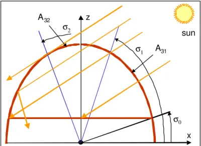
Figure 4 shows the beam light transmission when the sun is perpendicular to the skylight axis. The sun’s rays strike only a portion of the surface A3. The surface portion A31 (σ0≤ σ≤σ1) receives the directly-transmitted flux, and the surface portion A32 (σ1 ≤ σ ≤ σ2) receives the transmitted-reflected flux. Only the first reflections from the skylight interior surface are considered (multiple reflections occur over a small surface near the angle σ2). The incident, transmitted and absorbed light fluxes are expressed as follows:
ds cos E ds cos E Q 32 31 A b A b per =
∫
θ⋅ +∫
θ⋅ (15) ds cos ) ( ) ( E ds cos ) ( E QT 32 31 A b , 3 3 b A 3 b per =∫
⋅τ θ ⋅ θ⋅ +∫
⋅τ θ ⋅ρ θ ⋅ θ⋅ (16) ds cos ) ( ) ( E ds cos ) ( E QA 32 32 31 A b , 3 3 b A A f , 3 b per =∫
⋅α θ ⋅ θ⋅ +∫
⋅τ θ ⋅α θ ⋅ θ⋅ + (17)The incidence angle on an elemental surface (ds) of the surface A3 is expressed as follows: )
sin( cos
θ= θz+σ (18)
Performing the integration in equations (15), (16) and (17), one obtains:
{
cos( )-cos( )}
LRE d ) sin( E LR Qper b z b z 0 z 2 2 0 σ + θ σ + θ = σ σ + θ =∫
σ σ (19) d cos ) ( ) ( LR d cos ) ( LR E / QT 2 1 1 0 b , 3 3 3 b per∫
∫
σ σ σ σ σ ⋅ θ ⋅ θ ρ ⋅ θ τ + σ ⋅ θ ⋅ θ τ = (20) d cos ) ( ) ( LR d cos ) ( LR E / QA 2 1 2 0 b , 3 3 f , 3 b per∫
∫
σ σ σ σ σ ⋅ θ ⋅ θ α ⋅ θ τ + σ ⋅ θ ⋅ θ α = (21)where σ1 and σ2 are angles that delimit the surface portions A31 and A32, given by:
x
z
σ
0σ
1σ
2A
31A
32sun
Figure 4 Beam light transmission–sun perpendicular to the skylight axis.
) , -min( ); -, 2 -min( 0 z 0 2 z 0 1= σ +π θ π σ σ = π θ π σ σ (22) SUN AT AN ARBITRARY POSITION
Calculation of the transmitted and absorbed fluxes at an arbitrary solar azimuth angle is very complex to perform since it is not straightforward to find the skylight surface portions that correspond to the directly-transmitted and transmitted-reflected components of the incident flux using the ray tracing method. Rather, one opts to use a weighting factor to calculate the transmitted and absorbed fluxes based on the ones previously calculated for the sun positions parallel and perpendicular to the skylight axis.
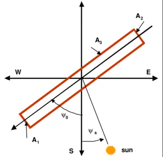
Figure 5 shows the position of the skylight with respect to the sun and the four cardinal directions. For a given skylight orientation, determined by the azimuth of the axis (ψ0) and the axis alignment A2-to-A1, the weighted transmitted and absorbed fluxes are expressed as follows:
[
1 W]
) ( QT W ) ( QT ) , (QTvault θz ψs = par θz ⋅ + per θz ⋅ − (23)
[
1 W]
) ( QA W ) ( QA ) , (QAvaut θz ψs = par θz ⋅ + per θz ⋅ − (24)
where:
QTvault : transmitted flux through the skylight surface (lumens); QAvault : absorbed flux by the skylight surface (lumens); and W : weighting function to be determined (dimensionless).
In equations (23) and (24), QTpar and QApar are calculated depending on the skylight axis orientation (A2 -to-A1) and the sun azimuth angle, as follows (note that ψs -ψ0 should be within the range 0 to 2π):
For 0 ≤ψs-ψ0≤π/2, or 3π/2 <ψs-ψ0≤ 2π, ) , A to A ( QT ) ( QTpar θz = par 2− − 1θz (25) ) , A to A ( QA ) ( QApar θz = par 2 − − 1θz (26) For π/2 <ψs-ψ0≤ 3 π/2, ) , A to A ( QT ) ( QTpar θz = par 1− − 2θz (27) ) , A to A ( QA ) ( QApar θz = par 1− − 2 θz (28) sun W E S ψ0 ψs A1 A2 A3
Figure 5 Position of the skylight with respect to the sun and the four cardinal directions.
For the incident flux, the following formula is, however, used, since the incident flux on the skylight surfaces can exactly be calculated:
(
)
(
)
{
cos cos cos sin sin sin cos( )}
LRE ) cos( sin S E Qvault= b 1 θz ψs −ψ0 + b θz σ0− σt + θz σ0− σt ψs −ψt (29)
where σt and ψt are the position and surface azimuth angles that correspond to the sun’s rays tangent to the skylight surface A3, or sun’s rays reaching the boundary of the surface A3 (note that σt = σ2 when the sun is perpendicular to the skylight axis). These are given by:
[
]
(
z s t 0)
1
t =minπ+tan tanθ ⋅cos(ψ −ψ , π−σ
σ − (30) π > ψ − ψ ψ − ψ π ≤ ψ − ψ ≤ ψ − ψ − = ψ − ψ 0 s 0 s 0 s 0 s t s if ), sin( 0 if ), sin( ) cos( (31)
The weighting function W can be determined by calculating the incident flux (Q3) on the skylight surface A3 at an arbitrary solar azimuth angle, and the incident fluxes for the parallel and perpendicular sun positions (Q3,par and Q3,per). The function W can, thus, be expressed as follows:
per , 3 par , 3 per , 3 3 Q Q Q Q W − − = (32)
Taking into account equations (5), (19) and (29), one obtains the following relation for the weighting function W:
{
}
) cos( ) cos( ) cos( ] sin [sin sin sin cos cos ) cos( W 2 z 0 z t s t 0 0 z t z 2 z σ + θ + σ − θ ψ − ψ σ − σ + σ θ + σ θ − σ + θ = (33)SKYLIGHT OPTICAL CHARACTERISTICS
The above analysis shows that all the parameters needed to calculate the skylight overall transmittance, absorptance and reflectance are now available. These are expressed as follows:
vault vault vault vault vault vault vault vault vault ; 1 Q QA ; Q QT α − τ − = ρ = α = τ (34)
SKYLIGHT EQUIVALENT OPTICAL CHARACTERISTICS
Introducing the concept of the optically equivalent flat skylight that has the same aperture surface area and yields the same transmitted, absorbed and reflected fluxes as the barrel vault skylight, the equivalent optical characteristics of barrel vault skylights are expressed as follows (Laouadi and Atif 1998; 1999):
ε ⋅ ρ = ρ ε ⋅ α = α ε ⋅ τ =
τeq vault ; eq vault ; eq vault (35)
where ε is the ratio of the incident flux on the skylight surface to that incident on the optically-equivalent flat surface, given by:
z h b vault s z cos A E Q ) , ( θ = ψ θ ε (36)
where Ah is the area of the skylight base surface. Substituting equation (29) in equation (35), one obtains:
(
)
(
0 t 0 t z s t) (
0)
z 0 s 0 0 0 0 s z cos 2 / ) cos( tan ] sin [sin cos cos tan ) cos( sin cos 2 / ) cos L 2 /( R ) , ( σ ψ − ψ ⋅ θ ⋅ σ − σ + σ − σ + θ ⋅ ψ − ψ ⋅ σ σ − σ − π ⋅ σ = ψ θ ε (37)RESULTS AND DISCUSSION
The previously developed model is applied to predict the skylight visible transmittance of high-rise vault skylights (σ0 = 0°). In the following, the effects of the skylight glazing types, dimensions and orientation with respect to the sun position on the skylight transmittance are investigated. The model is also used to predict the daily profile of the skylight transmittance for two skylight orientations during a typical summer day in the Ottawa region, Canada (latitude = 45o). Three combinations of skylight glazing types are considered, which are typically encountered in practice to control solar heat gains and daylight. (1) The top and gable surfaces have uniform double clear glazing (outer and inner panes are 6 mm clear float glass); this option may be considered to increase solar heat gains and daylight. (2) The top surface is double gray-tinted (outer pane 6 mm gray glass and inner pane 6 mm clear float glass) and the gable surfaces are double clear; this option may be considered to reduce solar heat gains while providing adequate daylight on the work plane during daytime. (3) The top surface is clear and the gable surfaces are opaque; this option may be considered to reduce/increase both solar heat gains and daylight. The transmittance and reflectance of the glass sheet at normal incidence angle are: clear glass (τ = 0.87 and ρf = ρb = 0.08), and gray glass (τ = 0.42 and ρf = ρb = 0.05) (Pilkington, 1988). At oblique incidence angles, the transmittance and reflectance of the glazing assembly are calculated using the Fresnel and Snell’s laws of optics.
EFFECTS OF SKYLIGHT GLAZING TYPES, DIMENSIONS AND ORIENTATION ON THE SKYLIGHT TRANSMITTANCE
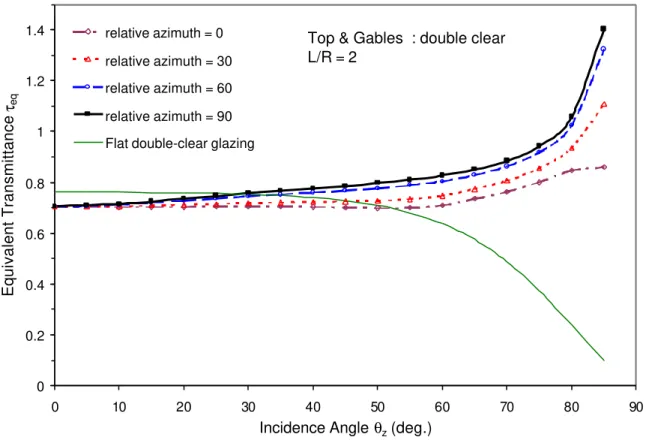
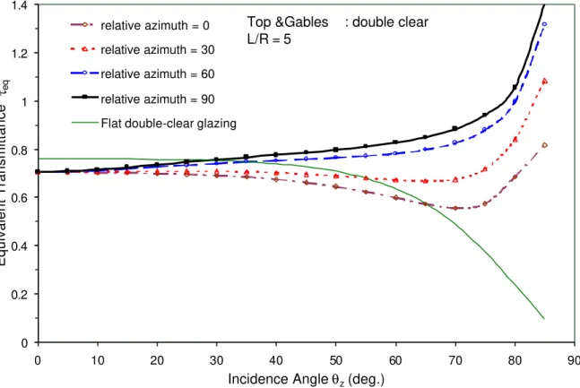
Figures 6 and 7 show the profile of the equivalent transmittance of short (L/R=2) and long (L/R=5) barrel vault skylights as a function of the incidence angle on a horizontal surface for a number of relative azimuth angles (|ψs - ψ0| = 0°, 30°, 60° and 90°). The top and gable surfaces of the skylight are double-glazed with 6 mm clear float glass. The transmittance profile of a similar flat skylight (with double clear glass) is also plotted in the figure. Contrary to flat skylights, vault skylights gather substantially more beam light at high incidence angles (i.e., low sun altitudes). For instance, at an incidence angle θz = 70° (e.g., winter days at noontime), vault skylights may transmit up to 80% of beam light higher than similar flat skylights, particularly when the sun is perpendicular to the skylight axis. However, at near normal incidence angles (e.g., summer days at noontime), vault skylights may transmit about 7% of beam light lower than similar flat skylights. As a result, depending on the site latitude and the day of the year, vault skylights with uniform glazing may yield lower or higher equivalent transmittance than that of flat skylights with similar glazing. For tropical regions
(latitude lower than 24°), vault skylights yield slightly lower equivalent transmittance at noontime than that of similar flat skylights in both winter and summer seasons. For higher latitudes, vault skylights yield slightly lower equivalent transmittance at noontime in summer and substantially higher equivalent transmittance in winter than that of similar flat skylights.
Vault skylights usually transmit more beam light when the sun is perpendicular to the skylight axis than when the sun is parallel to the skylight axis. The effect of the sun position on the equivalent transmittance is more pronounced for long skylights than for short ones. For square-based vault skylights (L/R=2), the equivalent transmittance at incidence angles θz < 85° may reach up to 25% higher when the sun is perpendicular to the skylight axis (|ψs - ψ0| = 90°) than that when the sun is parallel to the skylight axis (|ψs - ψ0| = 0° or 180°). For long vault skylights (L/R=5), the equivalent transmittance at incidence angles θz < 85° may reach up to 64% higher when the sun is perpendicular to the skylight axis than when the sun is parallel to the skylight axis.
0 0.2 0.4 0.6 0.8 1 1.2 1.4 0 10 20 30 40 50 60 70 80 90
Incidence Angle θz (deg.)
Equivalent Transmittance τeq relative azimuth = 0 relative azimuth = 30 relative azimuth = 60 relative azimuth = 90 Flat double-clear glazing
Top & Gables : double clear L/R = 2
Figure 6 Profile of the equivalent visible transmittance as a function of the incidence angle on a horizontal surface for short skylights with uniform glazing.
0 0.2 0.4 0.6 0.8 1 1.2 1.4 0 10 20 30 40 50 60 70 80 90
Incidence Angle θz (deg.)
Equivalent Transmittance τeq relative azimuth = 0 relative azimuth = 30 relative azimuth = 60 relative azimuth = 90 Flat double-clear glazing
Top &Gables : double clear L/R = 5
Figure 7 Profile of the equivalent visible transmittance as a function of the incidence angle on a horizontal surface for long skylights with uniform glazing.
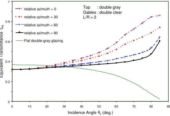
Figures 8 and 9 show the profile of the equivalent transmittance of short (L/R=2) and long (L/R=5) barrel vault skylights as a function of the incidence angle on a horizontal surface for a number of relative azimuth angles (|ψs - ψ0| = 0°, 30°, 60° and 90°). The top surface of the skylight is double gray-tinted glass, and the gable surfaces are double clear glass. The transmittance profile of a flat skylight with double gray-tinted glass is also plotted in the figure. Skylights with tinted top and clear gables gather substantially more beam light at high incidence angles (i.e., low sun altitudes) than flat skylights with similar top glazing. For instance, at incidence angle θz = 70°, vault skylights may transmit between 120% to 300% more beam light than flat skylights with similar top glazing, particularly when the sun is parallel to the skylight axis. Short square-based skylights transmit substantially more beam light than long skylights, particularly at off-normal incidence angles (θz > 30°). Contrary to skylights with uniform glazing (figures 6 and 7), the effect of the sun position on the equivalent transmittance of skylights with tinted top and clear gables is more pronounced for short skylights than for long ones. For short square-based vault skylights (L/R=2), the equivalent transmittance for incidence angles θz < 85° may reach up to 80% higher when the sun is parallel to the skylight axis than when the sun is perpendicular to the skylight axis. For long vault skylights (L/R=5), however, the effect of the sun position on the equivalent transmittance is not significant at incidence angles
0 0.2 0.4 0.6 0.8 1 0 10 20 30 40 50 60 70 80 90
Incidence Angle θz (deg.)
Equivalent Transmittance τeq relative azimuth = 0 relative azimuth = 30 relative azimuth = 60 relative azimuth = 90 Flat double-gray glazing
Top : double gray Gables : double clear L/R = 2
Figure 8 Profile of the equivalent visible transmittance as a function of the incidence angle on a horizontal surface for short skylights with tinted top and clear gables.
0 0.2 0.4 0.6 0.8 1 0 10 20 30 40 50 60 70 80 90
Incidence Angle θz (deg.)
Equivalent Transmittance τeq relative azimuth = 0 relative azimuth = 30 relative azimuth = 60 relative azimuth = 90 Flat double-gray glazing
Top : double gray Gables : double clear L/R = 5
Figure 9 Profile of the equivalent visible transmittance as a function of the incidence angle on a horizontal surface for long skylights with tinted top and clear gables.
Figures 10 and 11 show the profile of the equivalent transmittance of short (L/R=2) and long (L/R=5) barrel vault skylights as a function of the incidence angle on a horizontal surface for a number of relative azimuth angles (|ψs - ψ0| = 0°, 30°, 60° and 90°). The top surface of the skylight is glazed with double-clear glass and the gable surfaces are opaque with an interior constant reflectance ρb = 0.5. The transmittance profile of a flat skylight with double clear glass is also plotted in the figure. Vault skylights may transmit more or less beam light than similar flat skylights, depending on the relative sun position. At incidence angles θz < 80°, the equivalent transmittance of short skylights may reach up to 340% higher than that of similar flat skylights when the sun is perpendicular to the skylight axis. However, the equivalent transmittance of short skylights may reach up to 30% lower than that of similar flat skylights when the sun is parallel to the skylight axis. Long skylights may transmit up to 35% more beam light than short skylights, particularly when the sun is parallel to the skylight axis.
0 0.2 0.4 0.6 0.8 1 1.2 1.4 0 10 20 30 40 50 60 70 80 90
Incidence Angle θz (deg.)
Equivalent Transmittance τeq relative azimuth = 0 relative azimuth = 30 relative azimuth = 60 relative azimuth = 90 Flat double-clear glazing
Top : double clear Gables : opaque L/R = 2
Figure 10 Profile of the equivalent visible transmittance as a function of the incidence angle on a horizontal surface for short skylights with clear top and opaque gables.
0 0.2 0.4 0.6 0.8 1 1.2 1.4 0 10 20 30 40 50 60 70 80 90
Incidence Angle θz (deg.)
Equivalent Transmittance τeq relative azimuth = 0 relative azimuth = 30 relative azimuth = 60 relative azimuth = 90 Flat double-clear glazing
Top : double clear Gables : opaque L/R = 5
Figure 11 Profile of the equivalent visible transmittance as a function of the incidence angle on a horizontal surface for long skylights with clear top and opaque gables.
EFFECT OF THE SKYLIGHT ORIENTATION ON THE DAILY PROFILE OF THE SKYLIGHT TRANSMITTANCE
Figures 12 and 13 compare the daily profile of the equivalent transmittance for short (L/R=2) skylights aligned towards the west-east and the north-south directions during a typical summer day (June 21) in the Ottawa region, Canada (latitude 45°). Skylights with double-clear or gray-tinted glazing transmit much more beam light at off-noontime than at around noontime. Around noontime (10AM-2PM), the skylight orientation does not significantly affect the equivalent transmittance. However, at off-noontime (before 10AM or after 2PM), skylights with double-clear glazing transmit about 15% more beam light when aligned towards the north-south direction than when aligned towards the west-east direction. Skylights with gray-tinted glazing transmit about 50% more beam light when aligned towards the west-east direction than when aligned towards the north-south direction, particularly at off-noontime. Skylights with opaque gables transmit about 8% lower beam light around noontime and substantially more beam light at off-noontime when aligned towards the north-south direction than when aligned towards the west-east direction. Skylights with opaque gables or with double-clear glazing transmit approximately the same amount of beam light during most of the day when aligned towards the north-south direction.
0 0.2 0.4 0.6 0.8 1 1.2 1.4 4:30 6:30 8:30 10:30 12:30 14:30 16:30 18:30 Time (hr.) Equivalent Transmittance τeq
Top & Gables: double clear
Top: double gray; Gables: double clear Top: double clear; Gables: opaque
L/R = 2 E N W S June 21
Figure 12 Daily profile of the equivalent visible transmittance for short skylights aligned towards the west-east direction during a typical summer day (June 21) in Ottawa, Canada.
0 0.2 0.4 0.6 0.8 1 1.2 1.4 4:30 6:30 8:30 10:30 12:30 14:30 16:30 18:30 Time (hr.) Equivalent Transmittance τeq
Top & Gables: double clear
Top: double gray; Gables: double clear Top: double clear; Gables: opaque
L/R = 2 E N W S June 21
Figure 13 Daily profile of the equivalent visible transmittance for short skylights aligned towards the north-south direction during a typical summer day (June 21) in Ottawa, Canada.
Figures 14 and 15 compare the daily profile of the equivalent transmittance for long skylights aligned towards the west-east and the north-south directions during a typical summer day (June 21) in the Ottawa region, Canada (latitude 45°). Skylights with double-clear glazing transmit up to 48% more beam light when aligned towards the north-south direction than when aligned towards the west-east direction, particularly at off-noontime (before 10AM or after 2PM). Skylights with gray-tinted top and clear gables transmit approximately the same beam light when aligned towards the west-east or the north-south direction. Skylights with opaque gables and clear top transmit about 6% lower beam light at noontime, and substantially more beam light at off-noontime when aligned towards the north-south direction than when aligned towards the west-east direction. Skylights with opaque gables and clear top, or with uniform clear glazing transmit approximately the same amount of beam light during most of the day when aligned towards the north-south direction.
0 0.2 0.4 0.6 0.8 1 1.2 1.4 4:30 6:30 8:30 10:30 12:30 14:30 16:30 18:30
Time (hr.)
Equivalent Transmittance
τ
eqTop & Gables: double clear
Top: double gray; Gables: double clear Top: double clear; Gables: opaque
L/R = 5 E N W S June 21
Figure 14 Daily profile of the equivalent visible transmittance for long skylights aligned towards the west-east directions during a typical summer day (June 21) in Ottawa, Canada.
0 0.2 0.4 0.6 0.8 1 1.2 1.4 4:30 6:30 8:30 10:30 12:30 14:30 16:30 18:30
Time (hr.)
Equivalent Transmittance
τ
eqTop & Gables: double clear
Top: double gray; Gables: double clear Top: double clear; Gables: opaque
L/R = 5 E N W S June 21
Figure 15 Daily profile of the equivalent visible transmittance for long skylights aligned towards the north-south directions during a typical summer day (June 21) in Ottawa, Canada.
CONCLUSIONS
An analytical model based on the ray-tracing technique was developed to predict the optical characteristics of transparent barrel vault skylights. This was part of a project to develop analysis software for the optical characteristics and daylight performance of conventional and tubular skylights. The model can handle skylights with different shapes (high-rise to nearly-flat), different glazing types with/without coatings (gables opaque, or glazed with different glazing types from the cylindrical top surface), different dimensions (short, or long skylights), and different orientations (south/north, east/west, or any direction). The model was then used to investigate the effects of skylight glazing types, dimensions and orientation on the skylight visible transmittance. Barrel vault skylights have the following important features:
1. Vault skylights with uniform clear glazing transmit up to 64% more beam light when the sun is perpendicular to the skylight axis than when the sun is parallel to the skylight axis, particularly for long skylights (L/R=5).
2. Vault skylights with tinted top and clear gables transmit up to 300% more beam light when the sun is parallel to the skylight axis than when the sun is perpendicular to the skylight axis, particularly for short skylights (L/R=2).
3. Vault skylights with opaque gables and clear top transmit substantially more beam light when the sun is perpendicular to the skylight axis than when the sun is parallel to the skylight axis, particularly for short skylights (L/R=2).
When installed in mid-latitude regions, such as Ottawa, Canada (latitude = 45° north), short skylights (L/R=2) with uniform clear glazing transmit high beam light in summer days, and, therefore, high solar heat gains, whatsoever their orientation. Long skylights (L/R=5), however, transmit up to 45% more beam light when oriented towards the west-east direction compared to the north-south direction.
Short skylight (L/R=2) with gray-tinted top and clear gables, when oriented towards the west-east direction, transmit less beam light at noontime and high beam light at off-noontime, thus making them suitable to reduce solar heat gains when solar radiation is more intense while providing higher daylight during the daytime. When oriented towards the north-south direction, short skylights (L/R=2) with gray-tinted top and clear gables provide constant equivalent transmittance during most of the daytime, making them suitable to reduce both solar heat gains and daylight in sunny regions. However, long skylights (L/R=5) with gray-tinted top and clear gables provide constant equivalent transmittance during most of daytime, independently of their orientation, making them suitable to reduce both solar heat gains and daylight in sunny regions. Skylights with opaque gables and clear top transmit as much beam light as skylights with uniform clear glazing when oriented towards the north-south direction. However, when oriented towards the west-east direction, skylights transmit low beam light at off-noontime, particularly for short skylights, making them not practical.
REFERENCES
1. AAMA. Skylight Handbook, Design Guidelines. Des Plaines: American Architectural Manufacturers Association, 1987.
2. AAMA. Design for Energy Conservation with Skylights. Chicago: Architectural Aluminum Manufacturers Association, 1981.
3. ASHRAE. ASHRAE Handbook – 1997 Fundamentals. Atlanta: American Society of Heating, Refrigerating, and Air-Conditioning Engineers, Inc., 1997.
4. Allen T., Conventional and tubular skylights: An Evaluation of the daylighting systems at two ACT commercial buildings, Proceedings of the 22nd National Passive Solar Conference, Washington DC, pp. 97-129, 1997.
5. CANMET. VISION 4 Reference Manual. Ottawa: Canadian Centre for Mineral and Energy Technology, 1995.
6. Cassidy V.M., Booming Sales Have Skylight, Greenhouse Makers Smiling, Modern Metals, pp. 20-24, December, 1986.
7. Duffie J. A. And Beckman W. A. Solar Engineering of Thermal Processes. New York: John Wiley&Sons, Inc., 1991.
8. Heschong L. and McHugh J., Skylights: Calculating illumination levels and energy impacts, Illuminating Engineering Society, pp. 90-100, Winter 2000.
9. HMG. Skylighting design guidelines, Heschong Mahone Group (www.h-m-g.com), 2001.
10. HMG. Skylighting and Retail Sales, An Investigation into the Relationship between Daylighting and Human Performance, report, Pacific Gas and Electric Company, 1999.
11. IESNA. Lighting Handbook, Reference and Application Volume. New York: Illuminating Engineering Society of North America, 2000.
12. Jensen T. Skylights. Pennsylvania: Running Press, 1983.
13. Laouadi A., and Atif M.R. Daylight availability in top-lit atria: prediction of skylight transmittance and Daylight Factor. Lighting Research and Technology 32(4), pp. 175-186, 2000.
14. Laouadi A., and Atif M.R. Predicting optical and thermal characteristics of transparent single-glazed domed Skylights. ASHRAE Transactions, 105(2), pp. 325-333, 1999.
15. Laouadi A., and Atif M.R. Transparent domed Skylights: Optical Model For Predicting Transmittance, Absorptance And Reflectance. Lighting Research and Technology, 30(3), pp. 111-118, 1998.
16. LBL. WINDOWS 4.0 User Manual. Berkeley: Lawrence Berkeley Laboratory, 1992.
17. Pilkington. Glass and Transmission Characteristics of Windows, 7th edition. England: Harwills, 1988. 18. Treado S., Gillette G., and Kusuda T. Evaluation of the Daylighting and Energy Performance of
Windows, Skylights, and Clerestories. Report NBSIR 83-2726. U.S. Department of Commerce, 1983.
ACKNOWLDGEMENTS
This work was conducted as part of a project, funded by the Institute for Research in Construction of the National Research Council of Canada, PERD (Panel on Energy Research and Development), and NRCan (Natural Resources Canada). The authors are very thankful for their contribution.