Publisher’s version / Version de l'éditeur:
Vous avez des questions? Nous pouvons vous aider. Pour communiquer directement avec un auteur, consultez la
première page de la revue dans laquelle son article a été publié afin de trouver ses coordonnées. Si vous n’arrivez pas à les repérer, communiquez avec nous à [email protected].
Questions? Contact the NRC Publications Archive team at
[email protected]. If you wish to email the authors directly, please see the first page of the publication for their contact information.
https://publications-cnrc.canada.ca/fra/droits
L’accès à ce site Web et l’utilisation de son contenu sont assujettis aux conditions présentées dans le site LISEZ CES CONDITIONS ATTENTIVEMENT AVANT D’UTILISER CE SITE WEB.
Internal Report (National Research Council of Canada. Institute for Research in
Construction), 1999-10-01
READ THESE TERMS AND CONDITIONS CAREFULLY BEFORE USING THIS WEBSITE.
https://nrc-publications.canada.ca/eng/copyright
NRC Publications Archive Record / Notice des Archives des publications du CNRC : https://nrc-publications.canada.ca/eng/view/object/?id=21e3d8cf-4e2f-43a0-886d-63fd44cf119c https://publications-cnrc.canada.ca/fra/voir/objet/?id=21e3d8cf-4e2f-43a0-886d-63fd44cf119c
NRC Publications Archive
Archives des publications du CNRC
For the publisher’s version, please access the DOI link below./ Pour consulter la version de l’éditeur, utilisez le lien DOI ci-dessous.
https://doi.org/10.4224/20331287
Access and use of this website and the material on it are subject to the Terms and Conditions set forth at
User manual for SAFIR: a computer program for analysis of structures
at elevated temperature conditions
/ I
I
ser
1
TH1
National Research Conseil national1
~ 4 2 7
II
1*1
Council Canada de recherches CanadaI - I
I
1
no.
7 8 %;
User Manual for SAFlR A Computer
Program for Analysis of Structures at
Elevated Temperature Conditions
Daniel I. Nwosu,V.K.R. Kodur, J.M. Franssen, J.K. Hum
Internal Report 782 October 1999
NATIONAL RESEARCH COUNCIL OF CANADA INSTITUTE FOR RESEARCH IN CONSTRUCTION
USER MANUAL FOR SAFlR
A COMPUTER PROGRAM FOR ANALYSIS OF STRUCTURES AT ELEVATED TEMPERATURE CONDITIONS
Daniel I. Nwosu, V.K.R Kodur, J.M. Franssen, J.K. Hum
TABLE OF CONTENTS
List of Figures
...
iii...
List of Tables
...
111 1.0 INTRODUCTION...
I...
.
1 1 General I...
1.2 Analysis Procedure II
.
2.1 Thermal analysis...
I 1.2.2 Analysis of torsional stiffness of BEAM elements...
21.2.3 Structural analysis at elevated temperature
...
21.3 Capabilities of SAFIR
...
21.3.1 Capabilities based on temperature analysis
...
21.3.2 Capabilities based on torsion analysis
...
31.3.3 Capabilities based on structural analysis
...
31.4 Common Features in all Analyses
...
3...
1.5 Sign Conventions 4 1.5.1 Global and local axes...
41.5.2 Stresses
...
4...
2.0 INPUT DESCRIPTION 5...
2.1 Input for SAFlR.
5 . 2.2 Problem Defin~tlon...
52.3 General Data for Thermal Analysis
...
6...
2.4 General Data for Structural Analysis 7...
2.5 Material Properties 10 2.5.1 Stress-strain relations of concrete and steel...
10...
2.5.2 Parameters of the material laws.
I 0 ....
2.6 Convergence Crlterla 11 3.0 DETAILED INPUT DATA AND FORMAT...
123.1 Description and Format for Thermal Analysis Files
...
123.1 . 1 The
.
DAT file for thermal analysis...
123.1.2 The
.
STR file for thermal analysis...
173.2 Description and Format for Structural Analysis Files
...
27...
3.2.1 The.
DAT file for structural analysis 27 3.2.2 The.
STR file for structural analysis...
373.3 Description and Format for Torsional Analysis Files
...
483.3.1 The
.
DAT file for torsional analysis...
48...
3.3.2 The . STR file for torsional analysis 52 4.0 ELEMENT THEORY AND FORMULATIONS...
584.1 The TRUSS Element
...
584.1
.
1 Geometry...
584.1.2 Integration on the volume
...
584.1.3 Strain
...
584.1.4 Nodal forces
...
584.2 The BEAM Element
...
594.3 The SHELL Element
...
604.3.1 Geometry
...
604.3.2 Points of integration
...
614.3.3 Rebar
...
624.4 The SOLID Element
...
634.4.1 Internal voids
...
634.4.2 Convection
...
634.4.3 Radiation
. .
...
654.5 Convergence Cr~ter~a
...
654.6 Storage of Stiffness Matrix
...
66NOMENCLATURE
...
68iii Figure 1 Figure 2 Figure 3 Figure 4 Figure 5 Figure 6 Figure 7 Figure 8 Figure 9 Figure 10 Figure 11 Figure 12 Figure 13 List
of
Figures NDIM...
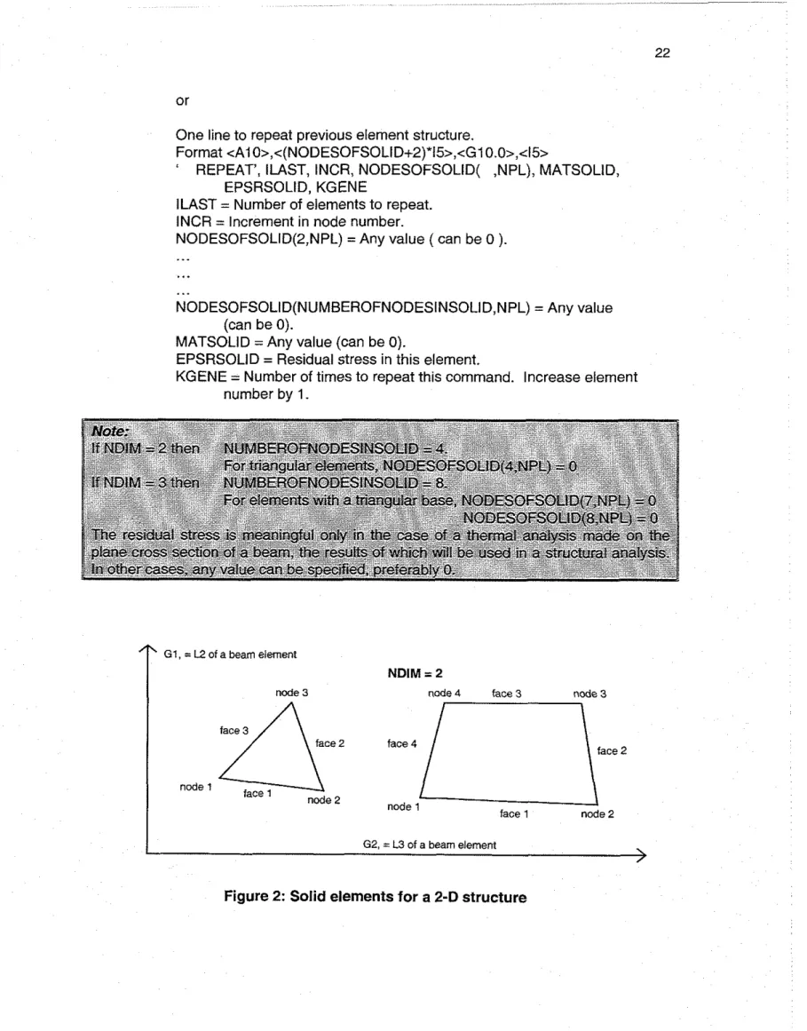
20Solid elements for a 2-D structure
...
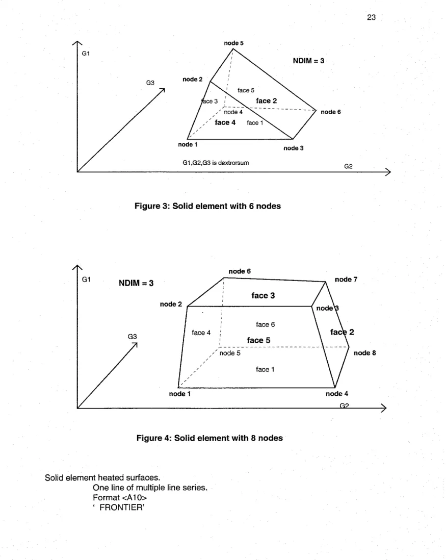
22Solid element with 6 nodes
...
23Solid element with 8 nodes
...
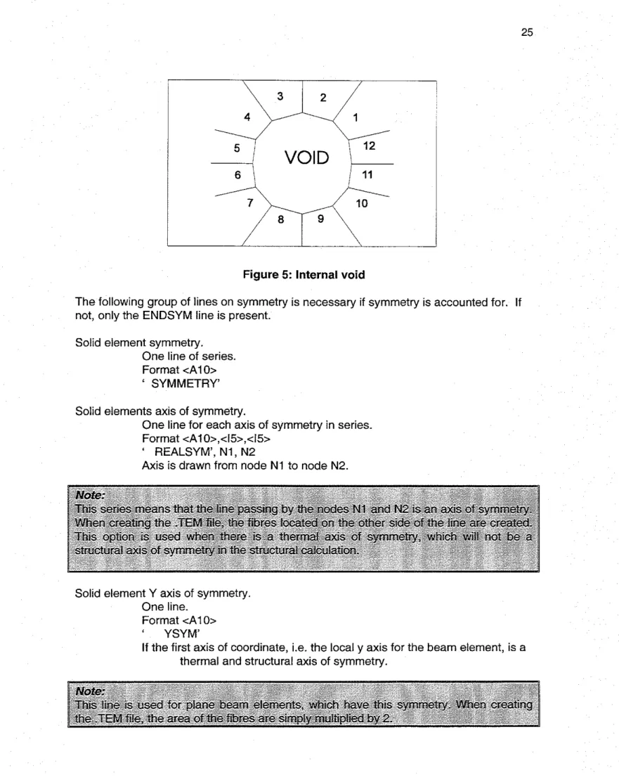
23Internal void
...
25...
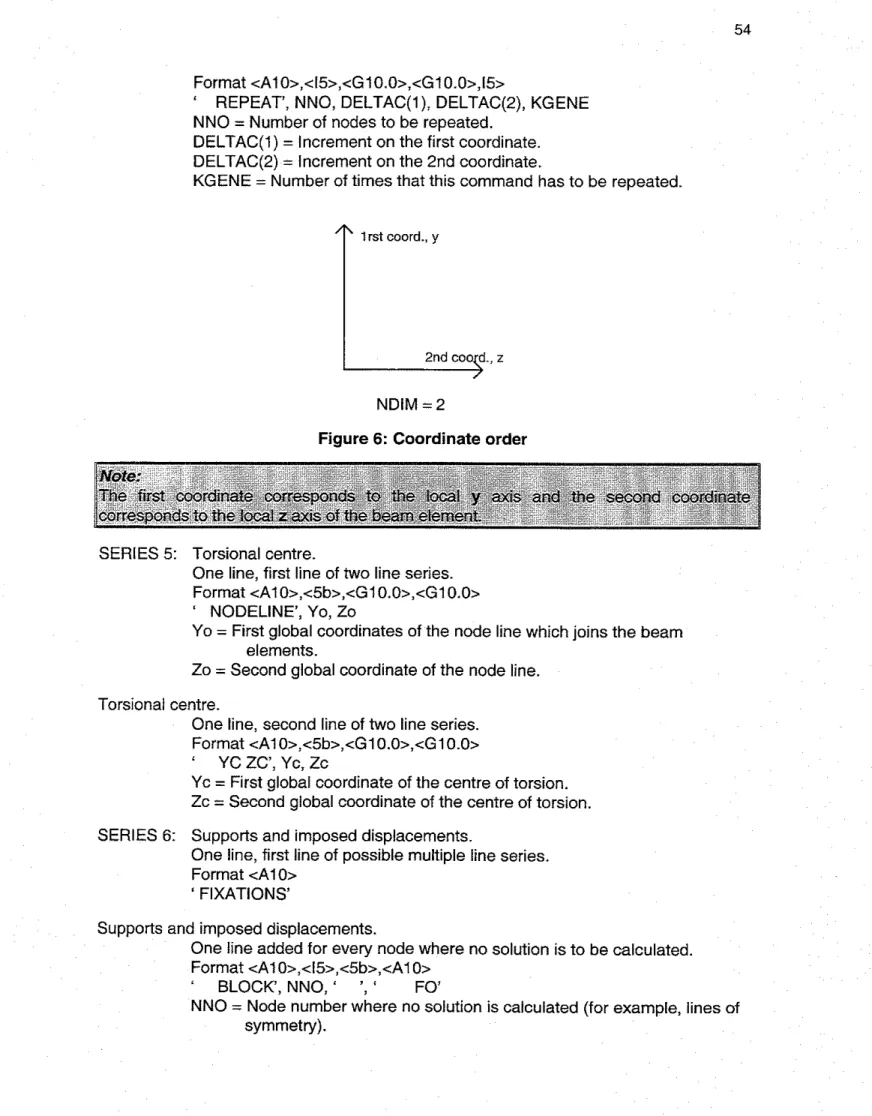
Coordinate order 54 Truss element...
58 Beam element...
60 Shell element...
61 Points of integration...
61 Rebar element...
62 Void frontier...
63 Convergence iterations...
66 List of Tables Table 1 Files and steps...
5Table 2 Input data file (.DAT) format for temperature analysis
...
6Table 3 Input data file (.STR) format for temperature analysis
...
7Table 4 Input data file (.DAT) format for structural analysis
...
81.0
INTRODUCTION
1.1 General
SAFIR is a special purpose computer program for the analysis of structures under ambient and elevated temperature conditions. The program, which is based on the Finite Element Method (FEM), can be used to study the behav~our of one, two and three-dimensional structures. The program (SAFIR) was developed at the University of Liege, Belgium, and is today v~ewed as the second generation of structural fire codes developed in Liege, the first generation being another computer program called Computer Engineering of the Fire design of Composite and Steel Structures (CEFICOSS)'~.
As a finite element program, SAFIR accommodates various elements for different
idealization, calculation procedures and various material models for incorporating stress- strain behaviour. The elements include the 2-D SOLID elements, 3-D SOLID elements, BEAM elements, SHELL elements and TRUSS elements. The stress-strain material laws include multi-linear or linear-elliptic for steel and non-linear for concrete.
The analysis procedure and the program capability are presented in this Chapter.
Details of the data files, material properties and cross sectional shapes are presented in Chapter 2. The detail input and format used in the program are given in Chapter 3, while Chapter 4 presents the theory and formulations of the elements available in the program.
1.2 Analysis Procedure
Using the program, the analysis of a structure exposed to fire may consist of several steps. The first step involves predicting the temperature distribution inside the structural members, referred to as thermal analysis. The torsional analysis may be necessary for 3-0 BEAM elements, a section subject to warping and where the warping function table and torsional stiffness of the cross section are not available. The last part of the
analysis, termed the structural analysis, is carried out for the main purpose of
determining the response of the structure due to static and thermal loading. The various stages of analysis are briefly outlined In the following sections.
1.2.1 Thermal analvsis
This analysis is usually performed while the structure is exposed to fire. For a complex structure, the sub-structur~ng technique is used, where the total structure is divided into several substructures and a temperature calculation is performed successively for each of the substructures. This kind of situation does arise in a structure where the members are made of different sections. For example, a frame structure wlth reinforced concrete columns, pre-stressed main beams and structural steel secondary beams, will require separate temperature analyses for each of the section types. From these analyses, the temperatures across the cross section are obtained and are stored for subsequent structural analysis where these sections are present.
The thermal analysis is made using 2-D SOLID elements, to be used later, on cross sections of BEAM elements or on the thickness of SHELL elements.
1.2.2 Analvsis of torsional stiffness of BEAM elements
This analysis is usually performed when analyzing structures with 3-D BEAM elements, either because non-uniform torsion and beam cross section were subject to warping (warping function is not equal to zero) or because the torsional stiffness is not available from tables or formulas. The 2-0 SOLID elements are used to calculate the warping function and the torsional stiffness of the cross section. The torsional properties obtained from this calculation are added to the results obtained from the temperature analysis of the same cross section for subsequent structural analysis. In cases where the warping function is not necessary, such as in the case of uniform torsion or a cross section with a warping function equal to zero, and if the torsional stiffness can be found in standard tables or by analytical formula, then this analysis need not be performed. In such situations, the torsional stiffness is simply introduced as a property of the cross section for the structural analysis.
1.2.3 Structural analvsis at elevated temoerature
For each calculation, the loads are applied to the structure, described as BEAM, TRUSS and SHELL elements. The temperature history of the structure, due to fire, is read from the files created during the temperature analysis. As the computation strategy is based on
a
step-by-step procedure, the following information can be obtained until failure occurs in the structure:Displacement at each node of the structure.
Axial and shear forces and bending moments at integration points in each finite element.
Strains, stresses and tangent modulus in each mesh at integration points of each finite element.
1.3 Capabilities of
SAFIR
SAFIR can be used for performing three different types of calculations, namely, thermal, torsional and structural analysis. The capabilities of the program based on these three analysis types are outlined in this section.
1.3.1 Capabilities based on temoerature analvsis
Plane sections as well as three-dimensional structures can be analyzed.
Plane sectlons are discretized by triangular andlor quadrilateral (rectangular and non-rectangular) elements, allowing representation of virtually all cross sectional shapes.
Three-dimensional structures are discretized by sol~d elements (prismatic and non- prismatic) with 6 or 8 nodes. This allows the representation of virtually all structure shapes.
The f ~ r e temperature, defined as a function of time, can either be the standard curves predefined in the code (IS0 834, ASTM E l 19, ULC S-101) or any other curve can be introduced through data points.
Cooling down phases can be considered.
Variation of material properties with temperatures, as well as the evaporation of moisture, can be considered.
Can analyze thermal performance of materials such as steel, reinforced concrete and composite steel-concrete sections. Other materials can also be analyzed provided their physical properties at elevated temperatures are known.
1.3.2 Ca~abilities based on torsional analysis
Allows virtually all cross section shapes to be represented. Materials are considered to be in the elastic stage.
1.3.3 Ca~abilities based on structural analvsis Plane or 3-D structures can be analyzed.
The structure is discretized by means of four different elements: Truss elements, made of one single material with one uniform temperature per element; beam elements, either pure steel, reinforced concrete or composite-steel sections; solid elements in which only thermo-elastic material laws are possible; and shell
membrane elements.
Large displacements are considered for truss, beam and shell elements. The effects of thermal strains (thermal restraint) can be accounted for. Material properties are non-linearly temperature dependent.
Unloading of material is parallel to the elastic-loading branch.
Local failure of a structural member that does not endanger the safety of the whole structure can be handled by means of the arc length technique.
Nodal coordinates can be introduced in the Cartesian or cylindrical system of axes. Imposed displacement (prescribed degrees of freedom) can be introduced.
Structures with external support inclined at an angle to the global axes can be analyzed.
Residual stresses (initial strains) can be accounted for. Pre-stressed structures can be analyzed.
Automatic adaptation of time step is possible and structural calculation continues until failure. This means that there are no deflection criteria to actually make the failure point. 1.4 Common Features in all Analyses
The common features in all computations are listed as follows:
Optimization of the matrix bandwidth to reduce the computer storage and calculation time can be performed by the program using internal re-numbering of the system equations. This re-numbering is transparent to the user.
The same temperature or the same displacement can be imposed at two different nodes by the use of master-slave relations.
Thermal and mechanical properties of the steel and concrete according to Eurocodes 2 , 3 and 4 are embedded in the code and can be used directly.
Graphic pre-processing and post-processing capabilities are by the PREPRO and DIAMOND97 codes, respectively. When needed, SAFIR could be adapted so as to give the results in a format compatible with commercial graphic softwaie, such as I-DEAS.
1.5 Sign Conventions
The following sign conventions are applied. 1.5.1 Global and local axes
Global axes are employed when defining a structure that is to be analyzed using SAFIR. This is done using the Cartesian system of coordinates. For the 2-0 (plane) problems, the axes are named G I and G2, while the local axes are named L1 and L2. Applied force and the displacements are positive in the direction of G I and G2; the applied moments and rotations are positwe in a counter-clockwise direction. For the 3-D problem, the global axes are named G I , G2 and G3 and the local axes are named L1,
L2
and L3. The movement GI-G2-G3 is dextrorsum; the applied force and moments, displacements and rotations are all positive in the G I , G2 and G3 directions.1.5.2 Stresses
The stresses are positive in tension. Axial forces, obtained as a summation of the stresses, are also positive in tension. Bending moments in the beam elements, obtained as a summation of
y,
o,,
withy,
measured on the local axis L1, are positive when fibres having a positive local coordinate are in tension.2.0 INPUT DESCRIPTION 2.1 Input for SAFIR
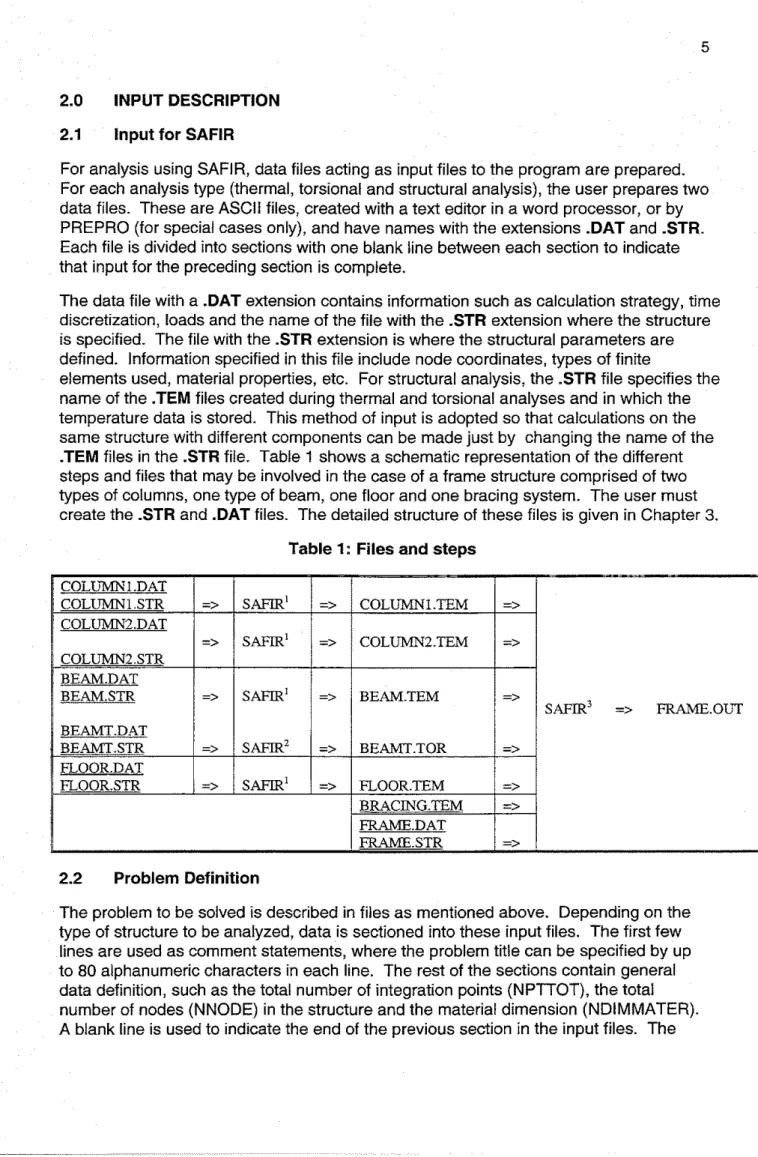
For analysis using SAFIR, data files acting as input files to the program are prepared. For each analysis type (thermal, torsional and structural analysis), the user prepares two data files. These are ASCII files, created with a text editor in a word processor, or by PREPRO (for special cases only), and have names w~th the extensions .DAT and .STR. Each file is divided into sections with one blank line between each section to indicate that input for the preceding section is complete.
The data file with a .DAT extension contains information such as calculation strategy, time discretization, loads and the name of the file with the .STR extension where the structure is specified. The file with the .STR extension is where the structural parameters are defined. Information specified in this file include node coordinates, types of finite
elements used, material properties, etc. For structural analysis, the .STR file specifies the name of the .TEM files created during thermal and torsional analyses and in which the temperature data is stored. This method of input is adopted so that calculations on the same structure with different components can be made just by changing the name of the .TEM files in the .STR file. Table 1 shows a schematic representation of the different steps and files that may be involved in the case of a frame structure comprised of two types of columns, one type of beam, one floor and one bracing system. The user must create the .STR and .DAT files. The detailed structure of these files is given in Chapter 3.
Table 1: Files and steps
2.2 Problem Definition
The problem to be solved is described in files as mentioned above. Depending on the type of structure to be analyzed, data is sectioned into these input files. The first few lines are used as comment statements, where the problem title can be specified by up to 80 alphanumeric characters in each line. The rest of the sections contain general data definition, such as the total number of integration points (NPTTOT), the total number of nodes (NNODE) in the structure and the material dimension (NDIMMATER). A blank line is used to indicate the end of the previous section in the input files. The
commands, format and number of lines required for a section in the input files are briefly given in the following sections.
2.3
General Data for Thermal AnalysisThe general data for thermal analysis is briefly described in Table 2 .DAT file and Table 3 .STR file. Each input line is comprised of a command followed by parameters for the command. Both the command and the parameters are written in a
predetermined format. Commands follow
a
10-character (A1O),
right justified format. Full details of all the commands and their parameters are given in Chapter 3.Table 2: Input data file (.DAT) format for temperature analysis
" TO,"
STEP'," NDDL", follow five character
RENUMPEW
Only RENWMGEO needs a parameter
" RENUMGEO"
Table 3: Input data file (.STR) format for temperature analysis
Parameter Format
2.4 General Data for Structural Analysis
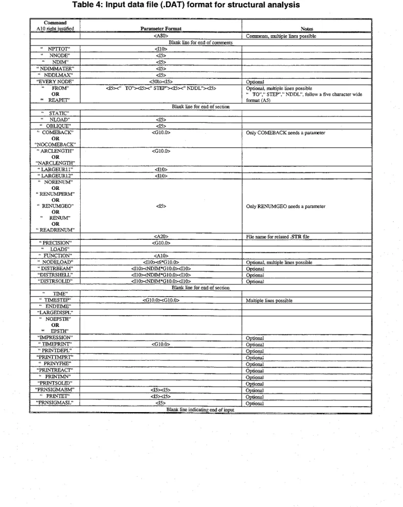
The general data for structural analysis is briefly presented in Table 4 .DAT file, and Table 5 .STR file. In each input line, a command is given followed by the parameters for the command. Both the command and the parameters are written in a predetermined format that is also given. Full details of all the commands are given in Chapter 3.
8
Table 4: Input data file (.DAT) format for structural analysis
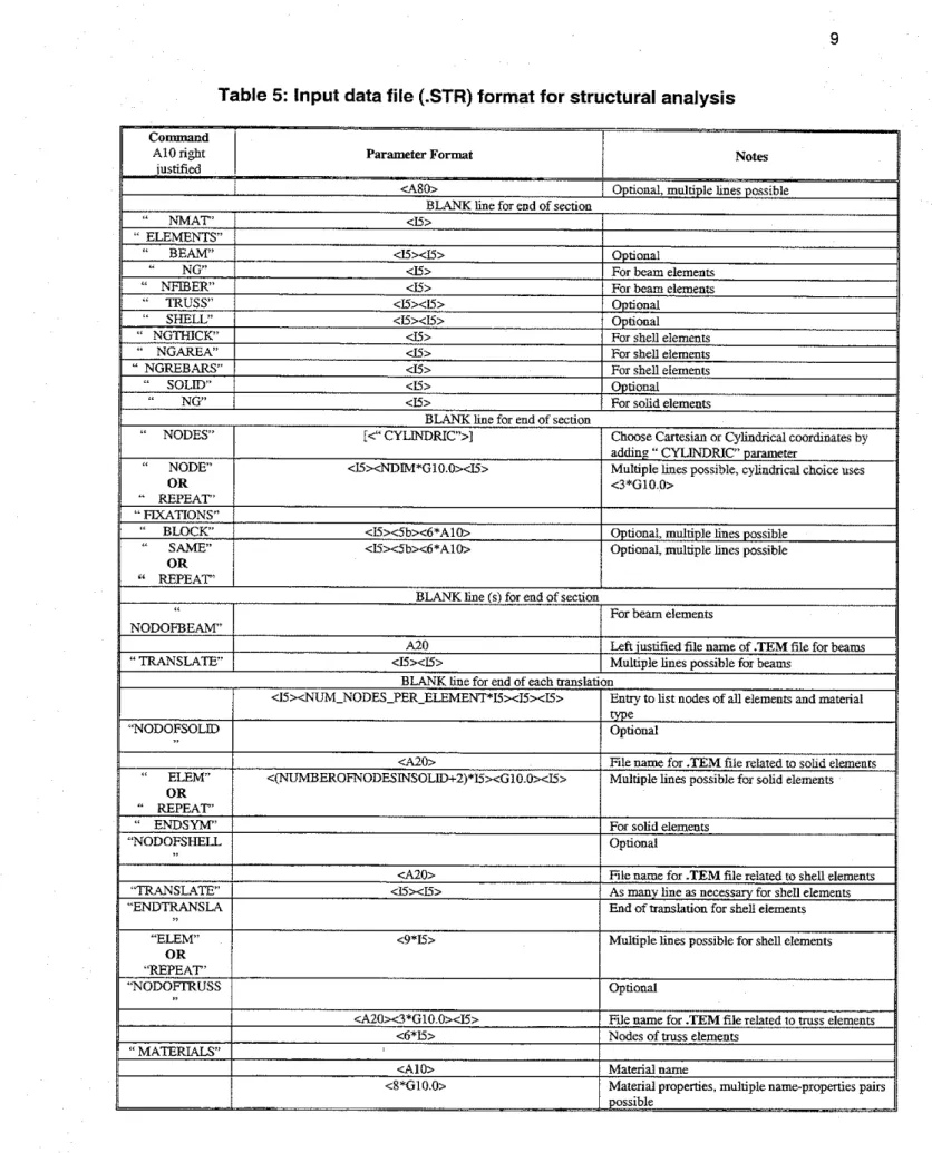
Table 5: Input data file (.STR) format for structural analysis
2.5 Material Properties
Material names are provided in the program by command CMAT(NM) and the values of the parameters associated with this command by PARACOLD(1,NM). There is a maximum of eight values of PARACOLD(1,NM) available in the program depending on the material name introduced in the CMAT(NM). Valid material names are:
INSULATION (does not carry any load), ELASTIC, BILIN, RAMBOSGOOD (only at room temperature), STEELEC3, STEELEC2, SILCONEC2 and CALCONEC2 (at elevated temperatures).
2.5.1 Stress-strain relations of concrete and steel
The relations in these materials are non-linear and are temperature dependent. In structures exposed to fire loads, the materials are subjected to initial strains (E,), thermal effects (E,) and stress related effects (E,). The stresses are, therefore, caused by the difference between the total strain (E,,), obtained from the nodal displacements, and the initial and thermal strains.
2.5.2 Parameters of the material laws
Both the steel and concrete materials can be modelled in the program by different material laws. For example, if CMAT(NM) is RAMBOSGOOD, the Ramberg-Osgood stress-strain relationship is used in the program to model both steel and concrete. For Ramberg-Osgood stress-strain relationships for unheated structures only, with material valid at 20°C, five parameters must be introduced by the user:
(a) PARACOLD(1 ,NM) =the Young's modulus (E)
(b) PARACOLD(2,NM) = any value or leave as blank space (c) PARACOLD(3,NM) = limit of proportionality (Ip)
(d) PARACOLD(4,NM) =exponent of the law (e) (e) PARACOLD(5,NM) =the factor of the law (D) Ramberg-Osgood strain:
If Stress (S) < Ip then Strain = SIE
Else Strain = S/E
+
((S-lp)/D)"For steel materials (STEELEC3, STEELEC2, STEELE3DC and PSTEELAIG), three parameters, according to the Eurocodes, must be introduced by the user:
(a) PARACOLD(1 ,NM) = E, the Young's modulus
(b) PARACOLD(2,NM) = any value or leave as blank space (c) PARACOLD(3,NM) = fy, the yield strength
For concrete materials that behave at elevated temperatures (CALCONCEC2 and SILCONCEC2) and Schneider model3 (CALCONSCH, SILCONCSCH and
LWCONCSCH), four parameters, according to the Eurocodes, must be introduced by the user:
(a) PARACOLD(1 ,NM) =any value or leave as blank space (b) PARACOLD(2,NM) = any value or leave as blank space (c) PARACOLD(3,NM)
=
f,, compressive strength(d) PARACOLD(4,NM) = f,, the tensile strength 2.6 Convergence Criteria
In order to converge to a solution, a tolerance value has to be specified in the program. SAFlR uses an iterative procedure to converge on the correct solution for each
increment. The precision given in the data file is a small value that must be reached at different tlmes in SAFlR calculations in order to have convergence. A good precision value is dependent on the type of structure that is being analyzed and information from preliminary runs. However, if the user does not know which to choose, a value of 0.001 can be used as a starting point. After the first run, an examination of the out-of-balance forces in the output can help the user to modify the corresponding precision value to obtain an acceptable value.
3.0
DETAILED INPUT DATA AND FORMAT3.1 Description and Format for Thermal Analysis Files
Parameter formats are specified as fixed length strings containing alphanumeric, integer or decimal values. Most labels and parameters are right justified with extra blank
spaces for padding. Most commands are left justified. Example:
<A10 > Represents a ten-character string of alphanumeric characters. <I52 Represents a five-character string containing an integer value. <G10.0> Represents a ten-character string containing a decimal value. <30b> Represents a thirty-character string containing only blank spaces. 3.1
.I
The .DAT file for thermal analvsisSERIES 1: Comments.
Any number of lines for comments. Format A80
Follow with one blank line to indicate the end of comments. SERIES 2: Number of integration points of the structure.
One line.
Format <A1 0>,<110> ' NPTTOT', NPTTOT
The user makes an estimate for this number and SAFlR verifies to ensure that NPTTOT is not too small. If the number is found to be small, SAFlR prompts the user to increase the value and indicates which value is to be used.
SERIES 3: Number of nodes of the structure One line.
Format <A1 0>,<15> ' NNODE', NNODE
SERIES 4: Number of global coordinate axes. One line.
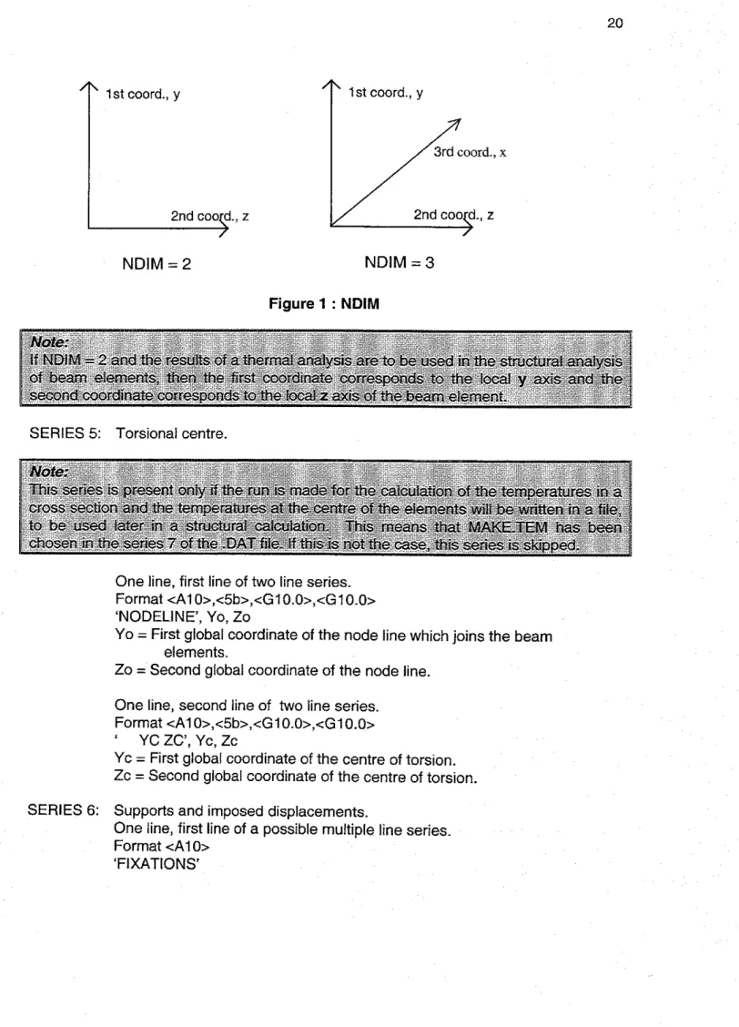
Format <A10>,<15> ' NDIM', NDIM
NDlM = 2 for plane structures. NDIM = 3 for 3-D structures. SERIES 5: Dimension of the material laws.
One line.
Format <A10>,<15>
' NDIMMATER', NDIMMATER NDIMMATER = 1 for thermal analysis
SERIES 6: Maximum degrees of freedom per node. One line, first line of series.
Format <A1 0>,<15>
' NDDLMAX', NDDLMAX
NDDLMAX
=
1 for thermal analysis. Degrees of freedom for all nodes.One line, second line series. Format <A10>,<308>,<15>
'EVERY NODE ', NNDL
Degrees of freedom for specific nodes. Multiple lines possible.
Format
<A10>,<15>,<A5>,<15>,<A5>,<15>,<A5>,<15>
' FROM', NNOI
,
' TO', NN02, 'STEP', NN03, ' NDDL', NDDL NNOI = First node of this group of nodes.NN02 = Last node of this group of nodes. NN03 = Node step.
NDDL = Number of D.0.F. for group of nodes, 0 or 1.
Note:
' i h e nodes: NNO1, NN01sNN03, NNOIi2xNN03,
...
NN02-2xNN03, NNO~-NNO~,/I
NN02 have NDDL D.0.F.Degrees of freedom for specific nodes by repeating existing ones. Multiple lines possible. One line for each set of nodes. Format <A1
0>,<15>,<A5>,<15>,<A5>,<l5>,<A5>,<15>
' REPEAT', NNOI, ' TO', NN02, ' STEP', NN03, ' TIME', NT NNOI = First node to be repeated.
NN02 = Last node to be repeated. NN03 = Node step.
SERIES 7: Thermal calculation.
One line for header, first line of four-line series. Format CAI O>
' TEMPERAT'
Thermal calculation time parameter.
One line for time integration, second line of four-line series. Format <A1 0>,<G10.0>
' TETA', TETA
TETA = Parameter for the time integration, 0 c TETA 1 (0.90 recommended).
Thermal calculation initial time.
One line for initial time, third line of four-line series. Format <A1 0>,<G10.0>
' TINITIAL', TlNlTlAL
TlNlTlAL =Temperature in the structure at time t = 0, normally taken as 20°C.
Thermal calculation output file type.
One line of three possible choices, fourth line of four-line series. Format <A1 O>
' MAKETEM' Store average element temperatures for beam fibres.
' MAKE.TSH' Store first NNODEl2 node temperatures describing shell element temperatures.
'
NOter
SERIES 8: Band width.
One Ilne, flrst line of two-line series. Format <A1 0>,<110>
' LARGEURI l', ILARGEURI 1
ILARGEURI I = Maximum length of K l 1 in the stiffness matrix K. Bandwidth of K12.
One line, second line of two-line series. Format <A1 0>,<110>
' LARGEUR12', ILARGEUR12
ILARGEUR12 = Maximum length of K12 in the stiffness matrix K.
SERIES 9: Renumbering strategy.
One line, choose from five possibilities. Format <A1 0>,[<15>]
' NORENUM' No renumbering of the equations.
' RENUMPERM' Renumbering of equations by logical permutations.
' RENUMGEO', NNOl Renumbering of equations by geometrical method
' RENUM' = RENUMGEO
+
RENUMPERMREADRENUM' Renumbering previously done, reread renumbering from .REN file.
NNOl = Node number where geometrical renumbering will start. NNOl = 0 Then renumbering started successively from all the nodes.
Note:
If RENUM or RENUMPERM is used, SAFlR stops after the renumbering. A subsequent run using READRENUM is required.
SERIES 10: File name.
One line, first line of two line series. Format <A202 Left justified.
'CFILENAME'
CFILENAME = Name of .STR file where the structure is described. File name for temperature file.
One line, second line of two line series. Format <A202 Left justified.
'CFILENAME'
CFILENAME = Name of file .TEM or .TEM or .TSH, where temperatures are stored.
SERIES 11 : Precision. One line.
Format <AlOz,<GIO.O> ' PRECISION', PRECISION
PRECISION = Small value which must be reached to have convergence.
SERIES 12: Time discretization.
One line, first line of several in series. Format <A1 0>
' TIME'
Time discretization time steps.
One line for each time step of multiple line series. Max of IDlMTlMESTEP lines.
Format <10bz,<GI O.O>,<G10.0>
10 blank characters, TIMESTEP, UPTIME TIMESTEP = T~me step in seconds.
UPTIME
=
Limit of validity of this time step. Time discretization last line.One line, last line in series. Format <A1 02
SERIES 13: Output results desired. Program running time increased with additional outputs requested.
One line, first line of possible multiple line series. Format <A1 O>
'IMPRESSION' Output results desired choice.
One line, second line of possible multiple line series. Format <A1 0>,<G10.0>
' TIMEPRINT', TIMEPRINT
TIMEPRINT
=
Output results time. Results written if Mod (TIME, TIMEPRINT) = 0, that is, if TIME is a product of TIMEPRINT. Output results multiple possible lines.One line added to series for each choice. Format <A1 O>
' PRINTDEPL' Write temperature variation each iteration (large amount of results).
' PRINTFHE' Write out of balance forces each iteration (large amount of results).
'PRINTREACT' Write reactions. One blank line, last line of series. Format <A80>
3.1.2 The .STR file for thermal analvsis SERIES
I:
Comments.Any number of lines for comments. Format <A80>
SERIES 2 : Number of materials.
One line.
Format<Al0>,<15> NMAT', NMAT
NMAT
=
Number of different materials.i Note:
If two materials have the same material law but different characteristics, it creates two different materials. e.g. 5235 and S355 steel.
SERIES 3: Number of different elements.
One line, first line of series. Format<Al O>
' ELEMENTS' Number of solid elements.
One line, second line of series. Format <A1 0>,<15>
' SOLID', NSOLID
NSOLID = Number of solid elements in the structure. Number of integration points.
One line, third line of series. ForrnatcAl0>,<15>
' NG', NG
NG
=
Number of integration points in each direction in the element. Not less than 1. Greater than 3 is not recommended.Number of voids.
One line, fourth line of series. Format <A1 0>,<15>
' NVOID', NVOID
NVOID = Number of internal voids. Number of elements around voids.
One line, optional line of series. Used when NVOID >
0
Format <A10>,<15>
'FRTIERVOID', NFRONTIERVOID
NFRONTIERVOID = Maximum number of elements enclosing the internal voids.
One blank line, last line of series. Format <A80>
SERIES 4: The nodes.
One line, first line of series. Format <A1 O>,[<Al O>] ' NODES', [' CYLINDRIC']
' CYLINDRIC' Parameter is used if the cylindrical coord~nate system is chosen instead of the Cartesian system. Cylindrical input as (r,B,Z)
and transformed to (X,Y,Z) for the internal solution process by X = r cos(8), Y = r sin(8). 0 is in degrees.
The Nodes position.
One line for a node added to series. Format <A1 O>,<lS>,<NDlM*Gl 0.0>,<15> '
NODE', NNO, RCOORDG(I,NNO), ..., RCOORDG(NDIM,NNO), KGENE
NNO = Number of the node.
Each node will have one positional entry along each global axis from one to NDIM.
Example:
RCOORDG(1 ,NNO)
=
First global coordinate of the node NNO. RCOORDG(2,NNO) = Second global coordinate of the node NNO.RCOORDG(ND1M-2,NNO) = Node NNO coordinate on global axis NDIM-2 RCOORDG(ND1M-1 ,NNO) = Node NNO coordinate on global axis NDIM-1 RCOORDG(NDIM,NNO)
=
Node NNO coordinate on global axis NDIM KGENE=
Automatic generation between previous defined node and thenode NNO.
KGENE = 0 or left blank ~f no generation
KGENE = I if equidistant generation from the last defined node.
One line for a repeated series added to series.
Format <AIO>,<NNO>,<DELTAC(l),
...,
<DELTAC(NDIM)>, <KGENE> ' REPEAT', NNO, DELTAC(I),...,
DELTAC(NDIM), KGENENNO
=
Number of nodes to be repeated.Each DELTAC( ) increment represents one of the global axis. DELTAC(1) = Increment on the first coordinate.
DELTAC(2) = lncrement on the second coordinate.
.
..
DELTAC(ND1M-2) = lncrement on the coordinate NDIM-2. DELTAC(ND1M-I) = lncrement on the coordinate NDIM-I. DELTAC(NDIM) = lncrement on the coordinate NDIM.
1'
1st mrd.. y'r
1 st coord., yNDIM
=2
NDIM
=3
Figure 1 : NDIM
SERIES 5: Torsional centre.
One line, first line of two line series. Format <A1 0>,<5b>,<GlO.O>,<GlO.O> 'NODELINE', Yo, Zo
Yo = First global coordinate of the node line which joins the beam elements.
Zo = Second global coordinate of the node line. One line, second line of two line series.
Format <A1 0>,<5b>,<G1O.Oz,<G10.0>
' YC
zc',
Yc, ZcYc = First global coordinate of the centre of torsion. Zc = Second global coordinate of the centre of torsion. SERIES 6: Supports and imposed displacements.
One line, first line of a possible multiple line series. Format <A1 O>
Supports and imposed fixations.
One line for each node as a f~xed block. Format <A1 0>,<15>,<5b>,<AI O>
' BLOCK', NNO, ' ', CBLOCK(I(NN0)
NNO = Node where the solution is not be calculated.
CBLOCK(1 ,NNO) = Function name describing the evolution of the solution at this node with respect to tlme. The temperature is the solut~on. Supports and lmposed displacements optional slave nodes
Optional line for each slave node. Format <A1 0>,<15>,<15>,<AI 0>
SAME', NNOI
,
NN02, CTRAV(1) NNOI = Number of the slave node. NN02 = Number of the master node. CTRAV(1) ='
YES'One line to repeat a previous SAME command. Format <A1 0>,<15>,<15>,<AI 0>
' REPEAT', NUMBER, INC, CTRAV(1)
NUMBER = Number of times the preceding SAME command is repeated. INCR = Increment on NNOI and NN02.
CTRAV(1) = ' YES'
Support and imposed displacements end of series. One blank line as last line of series. Format <A80>
SERIES 7: SOLID elements.
One line, first line of possible multiple line series. Format <A1 O>
'NODOFSOLID' Solid elements.
One line for each element.
Format <A1 O>,<(NUMBEROFNODESINSOLID+2)'15>,<G10.0>,<15> ' ELEM', NSOL, NODESOFSOLID( ..., NPL), MATSOLID, EPSRSOLID,
KGENE
NSOL = Number of this element.
NODESOFSOLID(1 ,NPL) = First node of this element. NODESOFSOLID(2,NPL) = Second node of this element.
.
..
. . .
. . .
NODESOFSOLID(NUMBEROFNODESINSOLID,NPL) = Last node of this element.
MATSOLID = Material of this element.
EPSRSOLID = Residual stress in this element.
KGENE
=
Generate from previously element up to this one, increment by node number.One line to repeat previous element structure.
Format
<AlO>,c(NODESOFSOLID+2)*l5>,<G10.0>,~15>
' REPEAT', ILAST, INCR, NODESOFSOLID( ,NPL), MATSOLID, EPSRSOLID, KGENE
ILAST = Number of elements to repeat. INCR = Increment in node number.
NODESOFSOLID(2,NPL) =Any value ( can be 0 ). ...
. . .
...
NODESOFSOLID(NUMBEROFNODESINSOLID,NPL) = Any value (can be 0).
MATSOLID = Any value (can be 0).
EPSRSOLID = Residual stress in this element.
KGENE
=
Number of times to repeat t h ~ s command. Increase element number by 1.'
GI, = L2 of a beam elementNDIM = 2
node 3 node 4 face 3 node 3
A
2 node 1 face l node 2 node 1 face 1 node 2 G2, = L3 of a beam element>
A node 5 3 node 6 node 1 Gl,G2.G3 is dextrorsum node 3 G2
Figure 3: Solid element with 6 nodes
'l'
node 6 G I NDIM=
3 face 3 face 6 face 5 - - . - - - - . - - - face 1 node I node 4Figure 4: Solid element with 8 nodes
Solid element heated surfaces.
One line of multiple line series. Format <A1
O>
Solid element heated elements.
One line for each heated surface of each heated element. Format <15>,<NUMBEROFFRONTlER*AS>,[<I5>]
NSOL, CFRONTIERSOLID(
...,
NSOL), KGENE NSOL = Number of the element.CFRONTIERSOLID(1 ,NSOL) =Temperature curve on the first face of the element.
...
CFRONTIERSOLID(NUMBEROFFRONTIER,NSOL)
=
Temperature curve on the last face of the element.KGENE = Increment the number of the elements.
Note
!
Temperature curve can be
a
predefined function (e.g., "FISO"), or a file name. I ISolid element separator line.
One blank line as separator line in series. Format <A80>
Solid element sub-series for voids among heated elements. One line, first line of possibly repeated sub series. Format <A1 O>.
' VOID'
Solid element sub-series for heated elements and voids.
One line for each heated element adjacent to a void. Format <Al0>,<15>,<15>,<15>
' ELEM', NSOL, NFRONTIER, KGENE NSOL = Number of the element.
NFRONTIER = Number of the frontier exposed to the internal void.
KGENE = Generate elements from the previous element. Can be positive or negative.
Solid element sub-series end.
One line, last line in sub-series. Format <A1 O>
Figure 5: Internal void
The following group of lines on symmetry is necessary if symmetry is accounted for. If not, only the ENDSYM line is present.
Solid element symmetry. One line of series. Format <A1 0> ' SYMMETRY' Solid elements axis of symmetry.
One line for each axis of symmetry in series. Format <A10>,<15>,</5>
' REALSYM', N1, N2
Axis is drawn from node N1 to node N2.
Sol~d element Y axis of symmetry. One line.
Format <A1 O> ' YSYM'
If the first axis of coordinate, i.e. the local y axis for the beam element, is a thermal and structural axis of symmetry.
Solid elements last line in series.
One line as last line in series. Format <A1 O>
' ENDSYM'
SERIES 8: Material description.
One line, first line of series. Format <A1 O>
' MATERIALS'
Material description sub-series, one sub-series for each different type of material used. One line, first line of two line sub-series.
Format <A1 0>[<15>] CMAT(NM), X
CMAT(NM) = Name of the material. Stored in array of NM items, Number Materials.
X = For user defined materials with temperature dependent properties only. Indicates number of temperature ranges with linear interpolation between temperatures.
1
Note:I
Vai~d mater~al names are:
'INSULATION',
1
STEELEC3, ' STEELEC2,
or
' PSTEELAI 6'I
'CALCONCEC2'. 'SILCONCECZ, 'CALCONCSCH', 'SILCONCSCH' 'LWCONCSCH'
"
USER?'Material description sub-series, material properties. One line, second line of two line sub-series. Format <8'G10.0>
Values of eight possible parameters depend on the material: If CMAT(NM) = INSULATION
PARACOLD(1 ,NM) blank.
PARACOLD(2,NM) Thermal conductivity k (WImK), if 0 then k = 0.04
+
0.00025 T.PARACOLD(3,NM) Specific heat (JIkgK). PARACOLD(4,NM) Specific mass (kg/m3). PARACOLD(5,NM) blank.
PARACOLD(6,NM) Convection coefficient on hot surfaces, if 0 then default value 25.
PARACOLD(7,NM) Convection coefficient on cold surfaces, if 0 then default value 9.
For the steel materials in temperature analysis PARACOLD(1 ,NM) blank. PARACOLD(2,NM) blank. PARACOLD(3,NM) blank. PARACOLD(4,NM) blank. PARACOLD(5,NM) blank.
PARACOLD(6,NM) Convectlon coefficient on hot surfaces, if 0 then default value 25.
PARACOLD(7,NM) Convectlon coefficient on cold surfaces, if 0 then default value 9.
PARACOLD(8,NM) Relative emissivlty, if 0 then default value 0.50. Thermal conductivity, specific heat, and specific mass are according to
Eurocode 3.
For the concrete materials in temperature analysis PARACOLD(1 ,NM) blank.
PARACOLD(2,NM) blank. PARACOLD(3,NM) blank. PARACOLD(4,NM) blank.
PARACOLD(5,NM) Moisture content ( kg/m3), if
0
then default value 92. PARACOLD(6,NM) Convection coefficient on hot surfaces, if 0 thendefault value 25.
PARACOLD(7,NM) Convection coefficient on cold surfaces, if 0 then default value 9.
PARACOLD(8,NM) Relative emissivity, if 0 then default value 0.50. Thermal conductivity, specific heat, and specific mass are according to
Eurocode 2.
For user defined materials for thermal analysis only PARACOLD(1 ,NM) Temperature ("C).
PARACOLD(2,NM) lambda. PARACOLD(3,NM) C. PARACOLD(4,NM) rho.
PARACOLD(5,NM) Moisture content ( kg/m3).
PARACOLD(6,NM) Convection coefficient on hot surfaces. PARACOLD(7,NM) Convection coefficient on cold surfaces. PARACOLD(8,NM) Relative emlssivity.
3.2
Description and Format for Structural Analysis Files
Structural input files follow the same general format as those used for thermal analysis. 3.2.1 The .DAT file for structural analysis
SERIES 1: Comments.
One line for each comment. Format <Ago>
One blank line to mark end of comments. Format <A80>
SERIES 2: Number of integration points. One line.
Format <A1 0>,<110z ' NPTTOT', NPTTOT
NPTTOT = Number of integration points in the structure
SERIES 3: Number of nodes. One line.
Format <A1 0>,<15> ' NNODE', NNODE
NNODE = Number of nodes of the structure. SERIES 4: Number of axes.
One line.
Format <A10>,<15> ' NDIM', NDlM
NDlM = Number of global axes, 2 for plane structures, 3 for 3-D structures. SERIES 5: Dimension of the material laws.
One line.
Format <A1 0>,<15>
'NDIMMATER', NDIMMATER
NDIMMATER
=
1 if all the materials used in the structure have uni-axial mechanical law= 2 if one of the materials used in the structure has bi-axial mechanical law (e.g. plane stress).
SERIES 6: Degrees of freedom. One I~ne, first line in series. Format <A10>,<15>
' NDDLMAX', NDDLMAX
NDDLMAX
=
Maximum number of degrees of freedom per node. if NDlM = 2 for truss elements, NDDLMAX 2for solid elements, NDDLMAX 2 for beam elements, NDDLMAX 3 if NDlM
=
3 for truss elements, NDDLMAX 3for solid elements, NDDLMAX 3 for shell elements, NDDLMAX 6 for beam elements, NDDLMAX 7
Degrees of freedom for specif~c nodes. One line added for each node. Format <A10>,<30b>,<15> 'EVERY NODE', NDDL
NDDL
=
Number of degrees of freedom for a specific node.Degrees of freedom for a series of nodes.
One line added for each series of nodes.
Format <A1 0>,<15>,<A5>,<15>,<A5>,<152,<A5>,<15>
FROM', NNOI, ' TO', NN02, ' STEP', NN03, ' NDDL', NDDL NNOI = First node of this group of nodes.
NN02 = Last node of this group of nodes. NN03
= Node step.
NDDL = Number of degrees of freedom for group of nodes.
1
Note:
' The nodes:
NNOI, NNOI+NN03, NN01+2~NN03,
...
NN02-2xNN03, NN02-NN03, NN02 of freedom.One line added for a repeating series of nodes, repeated copies get the same degrees of freedom as the original.
Format <A1 0>,<15>,cA5>,<I5>,<A5>,<l5>,<A5>,<15>
REPEAT', NNOI
,
' TO', NN02, ' STEP', NN03, ' TIME', NT NNOI = First node to be repeated.NN02 = Last node to be repeated. NN03 = Node step.
NT = Number of times that the nodes are to be repeated.
N o k
1
The command will create the following groups: I 1
f NNOl +NN03, NNOI+NN03+1,
...
NN02+NN03.
NN01+2xNN03, NN01+2xNN03+1,...
NN02+2NN03...
...
...
I...
...
.-..-
/
NNOI+NTxNN03, NNOI +NTxNN03+1,...
NN02+NTxNN03If NDlM
=
2:The nodes supporting truss and solid elements must have NDDL 2: translation in the global axis 1
translation in the global axis 2
The end nodes supporting beam elements must have NDDL 3: translation in the global axis 1
translation in the global axis 2 rotation about virtual global axis
The internal node of beam elements must have NDDL = 1:
2nd order component of the longitudinal displacement, no other elements must be linked to this node
If NDlM = 3:
The nodes supporting truss and solid elements must have NDDL 3: translation in the global axis 1
translation in the global axis 2 translation in the global axis 3
The end nodes supporting beam elements must have NDDL 7 : translation in the global axis 1
translation in the global axis 2 translation in the global axis 3. rotation about global axis 1. rotation about global axis 2. rotation about global axis 3. warping.
The internal node of beam elements must have NDDL
=
1 :2nd order component of the longitudinal displacement, only shell elements are allowed to be linked to this node.
The angle nodes of shell elements must have NDDL 6: translation in the global axis 1
translation in the global axis 2
translation in the global axis 3 rotation about global axis 1
rotation about global axis 2 rotation about global axis 3
The mid-side nodes of shell elements must have NDDL 1 :
2nd order component of the longitudinal displacement, only beam elements are allowed to be linked to this node.
SERIES 7 : Loads.
One line, first line of two line series. Format <A1
O>
Load number of vectors.
One line, second line of two line series. Format <A10>,<15>
' NLOAD', NLOAD
NLOAD = Number of load vectors. One load vector is made of the load that will vary with time according to the same function.
SERIES 8: Inclined supports. One line.
Format <A1 0>,<15> OBLIQUE', NOBLIQUE
NOBLIQUE
=
Number of inclined supports. SERIES 9: Convergence strategy.One line, first line of two line series, choice of two possible settings. Format <AlO>,[<GI 0.0>]
'COMEBACK', TlMESTEPMlN
'NOCOMEBACK'
TlMESTEPMlN = Minimum value for the time step in case of comeback only.
Convergence strategy.
One line, second line of two line series, choice of two settings. Format <AIO>,<GI 0.0>
'ARCLENGTH', X
'NARCLENGTH', X
32
SERIES 10: Bandwidth.
One Ilne, first line of two llne series. Format <A1 0>,<11 O>
'LARGEURI l', ILARGEURI 1
ILARGEURI I = Maximum length of K11 in the stiffness matrix K. Bandwidth.
One line, second line of two line series. Format <A10>,<110>
'LARGEUR12', ILARGEUR12
ILARGEUR12 = Maximum width of K12 in the stiffness matrix K.
SERIES I I: Renumbering strategy.
One line, choice of five options. Format <A1 0>,[<15>]
' NORENUM'
=
No renumbering of the equationsRENUMPERM' = Renumbering of equations by logical permutations. or
RENUMGEO', NNOl = Renumbering of equations by geometrical method. or
READRENUM' = Read a previous renumbering from a .REN file.
NO1 = Node number where the geometrical renumbering w ~ l l start. Only used by RENUMGEO. If NNOl = 0 renumbering is started successively from all the nodes.
Note:
/If
RENUM or RENUMPERM is used SAFIR stops after the renumbering. A subsequent' irun has to be made using READRENUMSERIES 12: File name. One line. Format <A20> 'CFILENAME'
Left justified name of the .STR file where the structure is described. SERIES 13: Precision.
One line.
Format <A1 O>,cG10.0> 'PRECISION', PRECISION
PRECISION = Small value that must be reached for convergence.
SERIES 14: Loading.
One line, first line of possible multiple line series. Format <A1 O>
' LOADS' Loading function.
One line, second line of possible multiple line series. Format <A1 O>,<A10>
' FUNCTION', CFORCE(NL0)
CFORCE(NL0) = Function showing how load vector NLO varies as a function of time.
Loading function possible multiple node loads.
One line added for each point load directed at a node. Format <A1 0>,<110>,<6*G10.0>
' NODELOAD', NNO, LOAD(?), LOAD(2), ..., LOAD(NDDL) NNO = Number of nodes where loads are applied.
LOAD(1) = Load at degrees of freedom 1. LOAD(2) = Load at degrees of freedom 2.
LOAD(NNDL) = Load at degrees of freedom NDDL
Loading on beam elements.
One line added for each element with a distributed load applied. Format <A1 O>,<ll O>,<NDIM'Gl 0.0>,<110>
'DISTRBEAM', NBM, TRAV(I), TRAV(2),
...,
TRAV(NDIM), KGENE NBM = Number of the specific BEAM under a distributed load.TRAV(1) = Uniformly distributed load in the direction of the first global axls. TRAV(2) = Uniformly distributed load in the direction of the second global
axis.
. . .
TRAV(NDIM) = Uniformly distributed load in the direction of the final global axis.
KGENE = If not equal to zero, distributed loads are generated between the previous element and the present element
Loading on shell elements.
One line added for each loaded shell element. Format <AIO>,<IIO>,<NDIM*GI O.O>,cllO>
'DISTRSHELL', NSH, TRAV(I), TRAV(2),
...,
TRAV(NDIM), KGENE NSH = Number of the specific SHELL element under distributed load. TRAV(1) = Uniformly distributed load in the direction of the first global axis. TRAV(2) = Uniformly distributed load in the direction of the second globalaxis.
...
TRAV(NDIM) = Uniformly distributed load in the direction of the final global axis.
KGENE = If not equal to zero distributed loads are generated between the previous element and the present element.
Loading on solid elements.
One l ~ n e added for each loaded solid element. Format <AIO>,<Il O>,<NDIMeGI 0.0>,<110>
'DISTRSOLID', NSOL, TRAV(I), TRAV(2),
...,
TRAV(NDIM), KGENE NSOL=
Number of the specific SOLID element under distributed load. TRAV(1) = Uniformly distributed load in the direction of the first global axis. TRAV(2) = Uniformly d~stributed load in the direction of the second globalaxis.
. . .
TRAV(NDIM) = Uniformly distributed load in the direction of the final global axis.
KGENE
=
If not equal to zero distributed loads are generated between the previous element and the present element.Loading end of series.
One blank line, last line of series. Format <Ago>
SERIES 15: Time discretization.
One line, first line of possible multiple line series. Format <A1
O>
' TIME' Time frames.
One line added for each time frame added. Maximum of IDIMTIMESTEP lines.
Format < I Ob>,<GI O.O>,<GI 0.0>
10 blanks characters, TIMESTEP, UPTIME TIMESTEP =Time step in seconds.
UPTIME = Limit of validity of this time step. Time last line.
One line, end of time discretization series. Format <A1 O>
' ENDTIME'
SERIES 16: Large displacements. One line.
Format <A1 0>
SERIES 17: Thermal elongation.
One line, choice of two options. Format <A1 O>
' NOEPSTH' If thermal elongation is not considered.
' EPSTH' If thermal elongation is considered. SERIES 18: Output results.
One line, first line of multiple line series Format <A1 O>
'IMPRESSION' Output results.
One line, second line of multiple line series. Format <A1 O>,<G10.0>
' TIMEPRINT', TlMEPRlNT
TlMEPRlNT = Time for the output of the results. Output optional results.
Add one line for each option chosen. Format <A10>,[<15>],[~15>]
' PRINTDEPL' The displacement variation is written at every iteration. or
'PRINTTMPRT' The temperatures in the fibres of the beam elements are written.
' PRINTFHE' The out of balance forces are written at every iteration.
'PRINTREACT' The reactions are written.
' PRINTMN' Print the internal forces of the beam elements.
or
'PRINTSOLID' Print the stresses in the solid elements.
'PRNSIGMABM', NBM, NG Print the stresses in a beam element. NBM Number of the beam element where stresses are printed. NG Integration point of the beam element where stresses are
'
PRINTET', NBM, NG Print the tangent modul~ in a beam element. NBM Number of beam element where moduli are printed.
NG Integration point of the beam element where moduli are printed.
'PRNSIGMASL', NSOL Print the stresses in a solid element.
NSOL Number of the solid element where the stresses are printed. Output results last line.
One blank line as last line of series. Format <A80>
3.2.2 The .STR file for structural analvsis SERIES 1: Comments.
One line for each comment added. Format <A80>
Comments end line.
One blank line as end to comment series. Format <A80>
SERIES 2: Number of materials. One line.
Format <Al0>,<15> ' NMAT', NMAT
NMAT = Number of different materials.
If two materials have the same material law but dierent characteristics, it makes two
SERIES 3: Number of different elements.
One line, first line of multiple line series. Format <A1 O>
' ELEMENTS'
Different elements, beam elements sub-series.
One line added to sub-series if beams are used in the structure. Format <A1 0>,<15>,<15>
' BEAM', NBEAM, NGEOBEAM
NBEAM = Number of BEAM elements in the structure.
Different elements, integration points, beam elements sub-series. One line.
Format <A10>,<15> ' NG', NG
NG = Number of longitudinal points of integration in elements. Cannot be less than 2. Greater than 3 is not recommended.
Dierent elements, fibres of beam elements, beam elements sub-series. One line.
Format <A1 0>,<15>
' NFIBER', NFIBERBEAM
NFIBERBEAM = Number of longitudinal fibres in the beam elements (the maximum value for all the different groups of geometrical
properties). Different elements, truss elements.
One line added to series if truss elements are used. Format <A1 0>,<15>,<15>
' TRUSS', NTRUSS, NGEOTRUSS
NTRUSS = Number of TRUSS elements in the structure.
NGEOTRUSS = Number of different groups of geometrical properties.
1
Note:!
One group of geometrical properties comprised elements that had the same materials,
the
same cross sectional area and the same temperature history.Different elements, shell elements sub-series.
One line, first line of four line sub-series. Format <A1 0>,<15>,<15>
' SHELL', NSHELL, NGEOSHELL
NSHELL = Number of SHELL elements in the structure.
NGEOSHELL = Number of different groups of geometrical properties.
Different elements, Shell elements sub-series shell thickness. One line, second line of four l~ne sub-series. Format <Al0>,<15>
' NGTHICK', NGSHELLTHICK
NGSHELLTHICK = Number of points of integration on the thickness of the elements. Cannot be less than 2.
Different elements, shell element sub-serges shell area. One line, third line of four line sub-series. Format <A1 0>,<15>
' NGAREA', NGSHELLAREA
NGSHELLAREA
=
Number of points of ~ntegration in each direction of the surface of the elements.Note:
If NGSHELLAREA
=
1 integration point(s)=
I 5=
1/3 q=
113 If NGSHELLAREA=
2 integration point(s)=
3 q = 116 q = 1165
= 416 q=
1/63 ! ;= 1/6 q=
416 If NGSHELLAREA=
3 integration @nt(s)=
4;
=
113 q = 1 / 3 , 5 = 115 5=35 rl=1/5i q = 1 / 5 < = 7/5 q = 3 / 5 / where and q are the natural coordinate systems of the shell surface. IDifferent elements, shell element sub-series rebar. One line, fourth line of four line sub-series. Format <A1 0>,<15>
' NREBARS', NREBARS
NREBARS
=
Number of REBAR layers in the shell elements. Different elements, solid elements.One line, first line of two line sub-series. Format <A1 0>,<15>
' SOLID', NSOLID
NSOLID = Number of SOLID elements in the structure. Different elements, solid elements integration points.
One line, second line of two line sub series. Format <A1 0>,<15>
' NG', NGSOLID
NGSOLID = Number of points of integration in each direction in the elements. Cannot be less than 1. Greater than 3 is not recommended.
Last line of series.
One blank line as last line of series. Format <A80>
SERIES 4: The nodes.
One line, first line of multiple line series. Format <A1 O>,[<AI Oz]
or
' NODES CYLINDRIC'
Adding ' CYLINDRIC' allows use of cylindrical coordinates (r,0,Z) instead of Cartesian coordinates (X,Y,Z). Cylindrical coordinates are processed by the formulas X = r cos(0) and Y = r sin(8).
Nodes.
One line added for each node.
Format <Al0>,<15>,<NDIM*G10.0>,<15>
' NODE', NNO, RCOORD(I,NNO),
...,
RCOORD(NDIM,NNO), KGENENNO = Number of the specific node.
RCOORD(1 ,NNO) = First global coordinate of the node NNO.
...
RCOORD(NDIM,NNO) = Last global coordinate of node NNO of NDIM global axis.
KGENE =Generate nodes between the previous node and the current node NNO.
KGENE = 0 if no generation
KGENE = 1 if equidistant generation from the last defined node.
Format
<Al0>,<15>,cNDIM*GI0.0>,<15>
' REPEAT', NNO, DELTAC(I),
...,
DELTAC(NDIM), KGENE NNO = Number of nodes to be repeated.DELTAC(1) = Increment on the first coordinate.
. . .
DELTAC(NDIM) = lncrement on the coordinate NDIM.
KGENE = Number of times that this command has to be repeated. SERIES 5: Supports and imposed displacements.
One line, first line of possible multiple line series. Format <A10>
'FIXATIONS'
I Note:
Supports and imposed displacements fixed blocks.
One line for each node where solution follows a defined function of time and the reaction must be calculated for up to six degrees of freedom. Format <Al0>,<15>,<5b>,<6*A10>
' BLOCK', NNO, '
',
CBLOCK(1 ,NNO),...,
CBLOCK(NDDLMAX,NNO) If NDDLMAX > 6 then an addit~onal line follows the previous one to specifybounds on other degrees of freedom.
One additional line for more degrees of freedom for a node. Format <20b>,<6*AI 0>
', CBLOCK(7,NNO), ..., CBLOCK(NDDLMAX,NNO) NNO = Number of the specific node where the solution must not be
calculated.
CBLOCK(1 ,NNO) = Function describing displacement for first D.0.F. at this node with respect to time.
CBLOCK(2,NNO) = Function describing displacement for second D.0.F. at this node with respect to time
. .
.CBLOCK(NDDLMAX,NNO) = Function describing displacement for last D.0.F. at this node with respect to time
Supports and imposed displacements slave nodes.
One line added for each slave node up to six degrees of freedom. Format <A1 0>,<15>,<15>,<6'AI
0>
'
SAME', NNOI, NN02, CTRAV(I), ..., CTRAV(NDDLMAX)
If NDDLMAX > 6 add a line to specify functions for additional degrees of freedom.
One line added for other degrees of freedom for a slave node. Format <20b>,<6*A10>
', CTRAV(7),
...,
CTRAV(NDDLMAX) NNOI = Number of the specific slave node.NN02
= Number of the master node.
CTRAV(1) = ' YES' If the solution is the same as at node NN02 and as at node NNOI for the D.0.F. 1.
CTRAV(NDDLMAX) = ' YES' If the solution is the same as at node NN02 and as at node NNOI for the D.0.F. 1.
NNOl for the D.0.F. 1. ' ' If there is no master-slave relation for this D.0.F.
NNOl for the last D.0.F. ' ' If there is no master-slave relation for this D.0.F.
One line added for repeating series of slave node nodes up to six degrees of freedom.
Format <Al0>,<15>,<15>,<6*AlO>
' REPEAT', NUMBER, INCR, CTRAV(I), ..., CTRAV(NDDLMAX) If NDDLMAX > 6 add a line to specify values for other degrees of freedom
for repeated nodes
One line added for specifying additional degrees of freedom. Format <20b>,<6*A10>
', CTRAV(I), ..., CTRAV(NDDLMAX)
NUMBER = Number of times that the preceding SAME command must be repeated.
INCR = Increment on NNOl and NN02.
CTRAV(1)
=
' YES' If the solution is the same as at node NN02 as at node NNOI for the D.0.F. 1. ' ' If there is no master-slave relation for this D.0.F....
CTRAV(NDDLMAX) = ' YES' If the solution is the same as at NN02 as at NNOI for the last D.0.F.
SERIES 6: BEAM elements.
'Note:
[This series is skipped if no BEAM element is present in the structure. One line, first line of possible multiple line series.
Format <A1
O>
'NODOFBEAM'
Beam elements file name sub-series. One sub-series for each type of element. One line, first line of sub-series.
Format <A202 'CFILENAME'
CFILENAME = Full name of the file where the information on this section type can be found. Usually the extension is .TEM. File name is left justified.
Beam elements sub-series material translation.
One llne added for each different material used in the section. Format <Al0>,<15>,<15>
' TRANSLATE', MATL, MATG
MATL = Local number of thls material in this section type. MATG =Global number of this mater~al in the structure.
Beam element sub series last line.
One blank line to mark end of sub-series. Format <A80>
Beam elements list.
One line for each beam element.
Format
<15>,~15>,~15>,<15>,[<15>],<15>,[<l5>]
NE, NODOFBEAM(1 ,NE),
...,
NODOFBEAM(4,NE), ITYPEBEAM(NE), KGENENE = Number of this element.
NODOFBEAM(1 ,NE) = F~rst end node of this element.
NODOFBEAM(3,NE) = Third (i.e. central) node of this element. NODOFBEAM(2,NE) = Second end node of this element.
NODOFBEAM(4,NE)
=
Fourth node of this element (present only ifNDlM = 3).
ITYPEBEAM(NE) =The section type of this element.
KGENE
=
Allows the generation from the previously defined element up to this one. KGENE gives the increment on the first 3 nodes.SERIES 7: SOLID elements
Note:
,This series is skipped if no SOLID element is present in the structure. One line, first line of multiple line series for solid elements. Format <A1
O>
'NODOFSOLID' Sol~d elements file names.
One line for each solid element *.TEM file. Format <A20> left justified.
'CFILENAME'
CFILENAME = Name of the file where the temperatures concerning the solid elements are read. Usually, this file has the extension .TEM.
Solid element list.
One line for each solid element.
Format <AlO>,<(NUMBEROFNODESINSOLID+2)*15>,<G10.0>,<15> ' ELEM', NS, NODE(I,NS),
...,
NODE(8,NS), SMAT, EPSRSOLID,KGENE
NS = Number of this element.
NODE(1,NS) = First node of this element. NODE(2,NS) = Second node of this element.
. . .
NODE(8,NS) = Last node of this element. SMATS = Material of this element.
EPSRSOLID =Any value, preferably 0.
KGENE = Allows the generation from the previously defined element up to this one. KGENE gives the increment on the node number.
Format ~AlO>,<NUMBEROFNODESINSOLID+2)'15>,cG10.0>,<15> ' REPEAT', NE, INC, NODE(2,NS),
...,
NODE(8,NS), MAT,EPSRSOLID, KGENE NE = Number of elements to repeat. INC = Increment on the node number. NODE(2,NS) =Any value ( can be 0 ).
...
NODE(8,NS) Any value ( can be 0 ).
MAT = Any value ( can be 0 ).
EPSRSOLID = Any value, preferably 0.
KGENE = Number of times that this command has to be repeated. The element numbers increase by 1.
For triangular based elements NODE(7,NS)
=
NODE(8,NS) = 0. Solid element last line.One line. Format <A1 O> ' ENDSYM' SERIES 8: SHELL elements.
Note:
,This series is skipped if no SHELL element is present in the structure. One line, first line of possible multiple line series.
Format <A1 0>
Shell elements file list.
One line, first part of shell element sub-series, one sub-series for each element type.
Format <A202 left justified 'CFILENAME'
CFILENAME = File name where the information concerning this section type is read.
Shell element material translation.
One line for each different material in section, second part of shell element sub-series.
Format <A10>,<15>,<15> ' TRANSLATE', N l
,
N2N1
=
Local number of this material in this section type. N2 = Global number of this material in the structure. Shell element series end of translation.One line. Format <A1 O> 'ENDTRANSLA' Shell element list.
One line for each shell element. Format <A1 0>,<9*15>
' ELEM', NSH, N1, N2, N3, N4, N5, N6, ITYPESHELL(NSH), KGENE
NSH
=
Number of the element. N1 = Node 1 (first corner). N4 = Node 4 (first side). N2 = Node 2 (second corner). N5 = Node 5 (second side). N3 = Node 3 (third corner). N6 = Node 6 (third side).ITYPESHELL(NSH)
=
Type of geometrical section. KGENE = Automatic generation on the element number.Format <A1 0>,<15>,<15>,<30b>,<l5>
' REPEAT', NSH, N1, ' ', NUMBER NSH = Number of elements to be repeated.
N1 = Node increment.
NUMBER = Number of times that the NSH elements have to be repeated SERIES 9: TRUSS elements.
Note: