HAL Id: hal-01874763
https://hal.laas.fr/hal-01874763
Submitted on 14 Sep 2018
HAL is a multi-disciplinary open access
archive for the deposit and dissemination of sci-entific research documents, whether they are pub-lished or not. The documents may come from teaching and research institutions in France or abroad, or from public or private research centers.
L’archive ouverte pluridisciplinaire HAL, est destinée au dépôt et à la diffusion de documents scientifiques de niveau recherche, publiés ou non, émanant des établissements d’enseignement et de recherche français ou étrangers, des laboratoires publics ou privés.
Potentialities of micro-supercapacitors as energy storage
buffers in embedded micro-systems
Anaïs Ferris, David Pech, Sebastien Garbarino, Daniel Guay
To cite this version:
Anaïs Ferris, David Pech, Sebastien Garbarino, Daniel Guay. Potentialities of micro-supercapacitors
as energy storage buffers in embedded micro-systems. Symposium on Design, Test,
Integra-tion and Packaging of MEMS/MOEMS (DTIP 2016 ), May 2016, Budapest, Hungary. 4p.,
Potentialities of micro-supercapacitors as energy
storage buffers in embedded micro-systems.
Anaïs Ferris, David Pech
Power Management System Integration Group LAAS-CNRS
Toulouse, France [email protected], [email protected]
Sebastien Garbarino, Daniel Guay
Energy, Materials, Telecommunications. INRS-EMT
Varennes, Canada
[email protected], [email protected]
Abstract— Thanks to their unique properties and potential applications in various smart electronic devices, micro-supercapacitors have been increasingly investigated for on-chip energy storage. In this presentation, we describe our most recent attempts to increase the areal capacitance and energy of micro-supercapacitors. We deposited hydrated ruthenium oxide onto a highly porous gold current collector to realize a 3D electrode with unprecedented performances, fully compatible with current micro-fabrication and silicon-based device technology. The resulting electrode exhibits a capacitance per surface area in excess of 3 F.cm−2, and — for the first time — an all-solid-state
micro-supercapacitor with a specific energy per surface area comparable to that of lithium-ion micro-batteries has been achieved, but with superior power and cycling stability.
Keywords — Micro-Supercapacitors, Pseudo-capacitors, Energy Storage, Micro-fabrication, RuO2.
I. INTRODUCTION
Energy autonomy keeps being a critical issue in the context of off-grid applications, such as autonomous wireless sensor networks, mostly being served by primary batteries. One solution to obtain a complete energetic autonomy of embedded micro-systems is to harvest and store the energy available in the environment, such as heat or vibrations [1]. Combining with the emerging importance of oxide-based energy storage devices such as batteries and supercapacitors in microelectronic mechanical system (MEMS) and nomad electronic device systems, the search for high performances active material and compatible electrode materials has been intensified in recent years [2, 3].
On-chip micro-supercapacitors show very interesting characteristics when it comes to these applications, because of their extended lifetime and high power density. However, they still suffer from a much lower areal energy (energy per footprint area) compared with micro-batteries [4].
Moreover, for on-chip applications, areal density is more important than volumetric density due to the limited area available for integrating components into a system. It is therefore crucial to consider the capacitance and the energy of micro-supercapacitors normalized to their footprint areas. To date, despite their excellent power performances, the reported
areal capacitance (i.e., normalized to the surface area) of micrometer-sized electrical double-layer capacitors typically ranges from 0.4 to 16.5 mF cm−2 [5–8].
This capacitance could be increased through the utilization of pseudo-capacitive materials, mainly transition metal oxides. The charge storage mechanism of these materials consist on rapid and reversible faradaic surface reactions [9] and offers a means of achieving high energy density at high charge– discharge rate. Hydrous ruthenium dioxide (RuO2.xH2O) is one of the most promising electrode materials for electrochemical capacitors because of its high specific capacitance [10, 11], low electrical resistivity [12], and fast reaction rate with protons in aqueous electrolytes as well as long cycle life [13].
While its high cost has limited its development for large supercapacitors, the use of this material becomes relevant and promising for micro-supercapacitors [14]. When we consider the size of the device, the amount of active material involved is limited, thus the cost is mainly determined by the fabrication processes and the assembly of the device.
The charge storage mechanism of pseudocapacitors involves the initial few nanometers from the surface; the performance of micro-supercapacitors is consequently limited by the very thin active layer of the electrodes. It is therefore necessary to build a 3D array of electrode, with high aspect ratio, to allow more active materials to be loaded per unit area [15]. An attractive approach to increasing the capacitance is to deposit the pseudo-capacitive material onto a high surface area structured support [16–18]. Reported capacitances for micro-supercapacitors electrode per surface area, build on 3D structure exceed 100 mF.cm-2 [19–22].
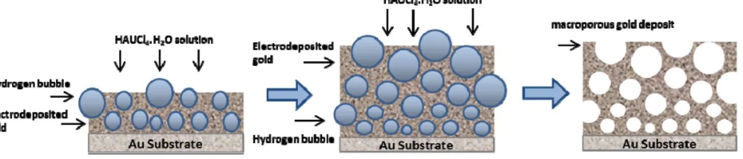
In this study, through a two-step electrochemical deposit, we have fabricated a porous gold/RuO2 electrode. The gold current collector is structured using the hydrogen bubble dynamic template synthesis [23–25], followed by the electrodeposition of the hydrous ruthenium oxide. The resulting electrode exhibits unprecedented high capacitance per surface area, in excess of 3 F cm−2. Such porous gold/ruthenium oxide hybrid structured electrode provides an encouraging alternative for integration of high-performance micro-supercapacitors onto silicon chips, components in which per-area performance is critical.
!
ABCD#DE"A"D#FEBD$G#$GHI#J""%K!"#$%5>>>%
II. EXPERIMENTAL WORK
A. Porous gold current collector
A 4 inches silicon wafer with evaporated Ti (100 nm) and Au (300 nm) was used as a substrate. Porous gold current collector was prepared by potentiostatic electrodeposition via the hydrogen bubbles dynamic template technique during 20 min from an aqueous solution consisting of 2 mM HAuCl4·3H2O in 2M H2SO4. The counter electrode was a platinum grid, 2 mm distant from the working electrode. The applied electrodeposition potential was -1.5 V vs. a saturated calomel electrode (SCE) using a VMP3 potentiostat (Biologic). At that potential, hydrogen bubbles arising from the reduction of protons occur on the surface of the working electrode, disturbing the diffusion layer and the localized current density. These bubbles affect the growth morphology and acts as a dynamic template for the growth of a porous gold layer [23– 25]. Figure 1 illustrates the major steps involved in the formation of the porous gold current collector.
B. Ruthenium-based electrode
Ruthenium dioxide is then electrodeposited onto the porous gold current collector by performing cyclic voltammetry (0.1 V to 0.95 V vs. SCE at 50 mV s-1) from an aqueous solution consisting of 5 mM of RuCl3·xH2O (99.9%) and 10-1 M KCl in 10-2 M HCl solution. The pH of the solution is adjusted with a 2.5 M KOH aqueous solution in order to have an optimized deposition involving both electrochemical and chemical reactions. The electrodeposition was performed in a thermostatic solution (50˚C) under agitation for 400 cycles) and the obtained film was annealed at 150˚C for 1h [26–27].
III. RESULTS AND DISCUSSION
Scanning electron microscopy (SEM) images in Figure 2, show the representative morphology for macro porous gold deposits consisting of a honeycomb network with interconnected and cross linked pores (Figure 2a). The diameter of the largest pores varies between 20 and 50 µm and pore size increases from bottom to the top of the substrate. The internal wall structure of these larger pores is composed of multi-branched dendrites and nodules of 100 nm width (Figure
2b & c), with pores as small as 50 nm.
Electrochemical characterization has been carried out on macroporous gold substrate. Figure 3 displays the corresponding steady-state cyclic voltammogram (CV) obtained for gold substrate (1 cm2 geometrical surface) before (black curve) and after using the hydrogen bubble dynamic template for gold synthesis (red curve). The two CVs exhibit the typical gold electrochemical response in sulfuric acid solution, with a double layer (from -0.2 to 0.5 V vs. SCE) and a gold oxide formation/reduction (from 0.6 to 1.6 V vs. SCE) potential regions. This layer has the electrochemical stability required for the subsequent RuO2 deposition as the formation of gold oxide only occurs above 1.0 V vs. SCE and thus will provide good mechanical stability at long cycles. In the cathodic sweep, the magnitude of the Au oxide reduction peak, centered at 0.8 V vs. SCE of both CVs has been compared. 25 µm
3 µm 400 nm
a
b
c
Figure 2. SEM Characterization of the porous gold current collector,
images at different magnifications showing different levels of pores.
-0,4 0,0 0,4 0,8 1,2 1,6 -80 -60 -40 -20 0 20 40 Cu rr en t ( m A. cm -2 ) Potential (V vs. SCE) Evaporated Au Macroporous Au Scan rate υ = 50 mV/s EASA = 1.38 cm² EASA = 410 cm²
Figure 3. Electrochemical characterization of the gold current collector.
Cyclic voltammogram of the porous Au compared with an Au thin film, in de-aerated 0.5 M sulfuric acid. The electrochemically active surface area of the porous gold coating is almost 300 times larger than the gold thin film.
Figure 1. Schematic illustration of the experimental procedure that generates porous gold film with open interconnected macroporous walls successfully sculptured
using the hydrogen bubble dynamic template synthesis.
!
The associated charge for the Au macroporous electrode (160 mC) is significantly higher than the one obtained for the Au thin film (0.54 mC). The coulombic charge involved in such reduction process [28], allowed us to determine reproducible values of electrochemical active surface area (EASA). The EASA of the bare gold and the macroporous gold deposits have been evaluated to be 1.4 and 410 cm2, respectively. Both electrochemical and scanning electron microscopy characterizations underline the significant increase of the specific surface area of gold substrate via the hydrogen bubble dynamic template synthesis.
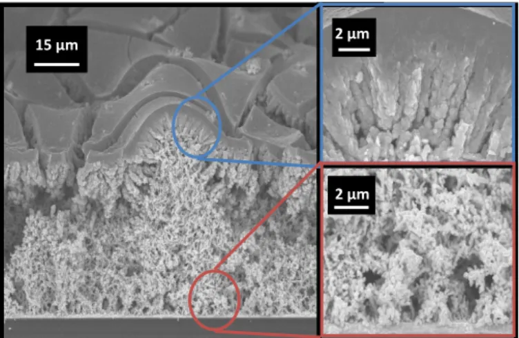
Following the macroporous gold structuration, electrodeposition of the pseudo-capacitive hydrous ruthenium oxide RuO2.xH2O onto the porous gold substrate has been carried out. The CVs of deposition has been recorded and display a change of the signal of ruthenium dioxide, with an increase of the thickness of the layer along the 400 cycles. From the SEM images (Figure 4) we note that the pseudo-capacitive hydrated RuO2.xH2O particles have been electrodeposited all along the nodule morphology of the porous gold layer, on the entire thickness from the top to the bottom of the substrate. The gold structure is fully covered by RuO2.xH2O with more dense ruthenium structure on the top of the substrate
The electrochemical performances of the electrode are then evaluated by cyclic voltammograms. In sulfuric acid, the theoretical electrochemical signature of pseudo-capacitive amorphous RuO2.xH2O is a butterfly-shape with an excellent reversibility. In Figure 5a, the CV of macroporous gold/RuO2.xH2O electrode shows, as expected, a roughly rectangular shape with the two quasi-symmetric peaks around 0.45 V vs. SCE with the progressive change of the oxidation state of ruthenium. This electrode exhibits an extremely high capacitance of 3288 mF.cm-2 when cycled at 5 mV.s-1. The rather impressive value delivered by this porous electrode outperforms the current state-of-the-art of micro-supercapacitors exhibiting capacitance values ranging from 0.4 to 100 mF.cm-2 [5–8, 19–22].
15 µm 2 µm
2 µm
Figure 4. SEM characterization of porous Au/RuO2.xH2O electrode. SEM
images of cross section of the electrode obtained after 400 cycles of RuO2
electrodeposition 0 10 20 30 40 50 0 10 20 30 40 50 -Im (Z ) ( Ω /c m ² ) Re (Z) (Ω/cm²) 10 mHz 0,9 1,2 0,00 0,75 350 Hz 100 kHz 0,0 0,2 0,4 0,6 0,8 1,0 -20 -10 0 10 20 30 C u rr en t dens it y ( mA .c m - ² ) Potential (V) vs SCE υ = 5 mV.s-1 0,0 0,2 0,4 0,6 0,8 1,0 1,2 1,4 1,6 1,8 2,0 2,2 2,4 2,6 2,8 3,0 V o lt am m e tr ic char ge q* ( C. c m -2) Sweep rate v -1/2 (s/mV)1/2 0,5 mV.s-1 50 mV.s-1 5 mV.s-1 0 1 2 3 4 5 0,0 0,1 0,2 0,3 0,4 0,5 20 mV.s-1 5 mV.s-1 0,5 mV.s-1 V o lt am m et ri c char ge q* -1 ( cm 2.C -1) Sweep rate (mV/s)1/2
a
d
c
b
CT = 3746 mF.cm-2 C0 = 3342 mF.cm-2Figure 5. Characterization of the porous Au/RuO2.xH2O electrode. a) Corresponding CV at 5 mV.s-1 in de-aerated 0.5 M sulfuric acid electrolyte. b)
Corresponding EIS Nyquist plot. c) Determination of the outer capacitance (CO) of the electrode. d) Determination of the total capacitance (C T) of the electrode.
!
The equivalent series resistance (ESR) is also very low (1.0 Ω.cm-2) with a quasi-negligible high-frequency semicircle, as shown in the Nyquist plot (Figure 5b). In the low-frequency region, a sharp increase of the imaginary portion of the impedance is observed with a nearly vertical straight line, as it is expected for a capacitive behavior with no leakage current.
To complete the study, the accessibility has been investigated by calculating the voltammetric charge (q*) as a function of the sweep rate (ʋ), as described by Trassati, [29, 30], to identify the outer charge, qouter, related to the more
accessible active sites. The value of qouter is obtained from the
extrapolation of q* to ʋ = ∞ (Figure 5c), whereas the total charge is estimated from the extrapolation of q* to ʋ = 0 (Figure 5d). From these extrapolations, we obtained a qouter
value of 2.84 C.cm−2 (3.34 F.cm−2) for a total charge of 3.19 C.cm−2 (3.75 F.cm−2). Therefore, q
outer represents 90% of
the total charge, i.e., most of the full storable charge is rapidly accessible, fulfilling a substantial requirement for a supercapacitor.
The use of a structured 3D current collector enhances the utilization efficiency of the hydrated ruthenium oxide and provides short transport/diffusion path lengths for protons and electrons.
IV. CONCLUSION
We have combined a dynamic technique of gold synthesis called hydrogen dynamic bubble template, with the electrodeposition of hydrated ruthenium dioxide to achieve a micro-supercapacitor electrode with extremely high performances. The porous gold current collector exhibits an important electrochemical active surface area of 410 cm2 with a macro porous honeycomb-like structure. The efficient RuO2.xH2O electrodeposition all along the substrate structure allows obtaining a capacitance of 3.3 F.cm-2.
In conclusion, with a cost of material estimated to be less than 60 cents cm−2, this porous Au/RuO
2.xH2O electrode is positioned remarkably well in terms of specific capacitance compared to other device electrodes.
Another key feature is the possibility offered by this structure to be transferred onto an interdigitated electrode configuration device. Additionally, resolution can be at first fixed at 500 µm and then optimized to reach 100 µm which is promising for further development of high performance stand-alone supercapacitors that can be used is wearable applications, in which the key consideration is to minimize footprint occupancy while maximizing the energy.
ACKNOWLEDGMENT
This work was partly supported by the French RENATECH network (D.P.) and the Canada Research Chair program (D.G.).
REFERENCES
[1] Z. L. Wang, Adv. Mater. 2012 , 24 , 280 . [2] A. Burke, J. Power Sources, 91, 37–50 (2000).
[3] J. G. Koomey, H. S. Matthews, E. Williams, Annu. Rev. Environ. Resources 2013, 38, 17.1.
[4] M. Beidaghi, Y. Gogotsi, Energy Environ. Sci. 2014, 7, 867.
[5] P. Huang, D. Pech, R. Lin, J. K. McDonough, M. Brunet, P. L. Taberna, Y. Gogotsi, P. Simon, Electrochem. Commun. 2013, 36, 53.
[6] T. M. Dinh, D. Pech, M. Brunet, A. Achour, J. Phys.: Conf. Ser. 2013, 476, 012106.
[7] D. Pech, M. Brunet, P. L. Taberna, P. Simon, N. Fabre, F. Mesnilgrente, V. Conédéra, H. Durou, J. Power Sources 2010, 195, 1266.
[8] D. Pech, M. Brunet, H. Durou, P. Huang, V. Mochalin, Y. Gogotsi, P. L. Taberna, P. Simon, Nat. Nanotechnol. 2010, 5, 651.
[9] T. Brousse, D. Bélanger, J. W. Long, J. Electrochem. Soc. 2015, 162, A5185.
[10] S. Hadzi-Jordanov, H. Angerstein-Kozlowska, M. Vukovic and B. E. Conway, J. Electrochem. Soc. 125, 1471 (1978).
[11] I.D. Raistrick in “The Electrochemistry of Semiconductors and Electronics-Processes and Devices”, p. 297, ed. J. McHardy and F. Luduig, Noyes, New Jersey (1992).
[12] S. Trasatti and G. Lodi in “Electrodes of Conductive Metallic Oxides-Part A”, p. 301, ed. S. Trasatti, Elsevier, New York (1980).
[13] W. Deng, X. Ji, Q. Chen, C. E. Banks, RSC Adv. 2011, 1, 1171. [14] C. C. Liu, D. S. Tsai, S. Susanti, W. C. Yeh, Y. S. Huang, F. J. Liu,
Electrochim. Acta 2010, 55, 5768.
[15] S. Li, X. Wang, H. Xing, C. Shen, J. Micromech. Microeng. 2013, 23, 114013.
[16] B. L. Ellis, P. Knauth, T. Djenizian, Adv. Mater. 2014, 26, 3368. [17] X. Lang, A. Hirata, T. Fujita, M. Chen, Nat. Nanotechnol. 2011, 6, 232. [18] J. Han, Y. C. Lin, L. Chen, Y. C. Tsai, Y. Ito, X. Guo, A. Hirata,T.
Fujita, M. Esashi, M. Gessner, M. Chen, Adv. Sci. 2015, 2, 1500067. [19] X. Wang, Y. Yin, X. Li, Z. You, J. Power Sources 2014, 252, 64. [20] A. Ponrouch, S. Garbarino, D. Guay, J. Power Sources 2013, 221, 228. [21] W. Wang, S. Guo, I. Lee, K. Ahmed, J. Zhong, Z. Favors, F. Zaera, M.
Ozkan, C. S. Ozkan, Sci. Rep. 2014, 4, 4452.
[22] T. M. Dinh, A. Achour, S. Vizireanu, G. Dinescu, L. Nistor, K. Armstrong, D. Guay, D. Pech, Nano Energy 2014, 10, 288.
[23] B. J. Plowman, A. P. O’Mullane, P. R. Selvakannan, S. K. Bhargava, Chem. Commun. 2010, 46, 9182.
[24] S. Cherevko, C. H. Chung, Electrochem. Commun. 2011, 13, 16. [25] J. Liu, L. Cao, W. Huang, Z. Li, ACS Appl. Mater. Interfaces 2011, 3,
3552.
[26] C. C. Hu, Y. H. Huang, J. Electrochem. Soc. 1999, 146, 2465.
[27] J. J. Jowa, H. J. Lee, H. R. Chena, M. S. Wu, T. Y. Wei, Electrochim. Acta 2007, 52, 2625.
[28] L. D. Burke, P. F. Nugent, Gold Bull. 1997, 30, 43.
[29] S. Ardizzone, G. Fregorana, S. Trasatti, Electrochim. Acta 1990, 35, 263.
[30] J. Gaudet, A. Tavares, S. Trasatti, D. Guay, Chem. Mater. 2005, 17, 1570.