HAL Id: hal-01835980
https://hal.archives-ouvertes.fr/hal-01835980
Submitted on 11 Jul 2018HAL is a multi-disciplinary open access archive for the deposit and dissemination of sci-entific research documents, whether they are pub-lished or not. The documents may come from teaching and research institutions in France or abroad, or from public or private research centers.
L’archive ouverte pluridisciplinaire HAL, est destinée au dépôt et à la diffusion de documents scientifiques de niveau recherche, publiés ou non, émanant des établissements d’enseignement et de recherche français ou étrangers, des laboratoires publics ou privés.
Magnetic modulation of inverse Spin Hall Effect in
lateral spin-valves
T. Andrianov, A Vedyaev, Bernard Dieny
To cite this version:
T. Andrianov, A Vedyaev, Bernard Dieny. Magnetic modulation of inverse Spin Hall Effect in lateral spin-valves. Journal of Physics D: Applied Physics, IOP Publishing, 2018, 51 (20), �10.1088/1361-6463/aabb75�. �hal-01835980�
1
Magnetic modulation of inverse Spin Hall Effect in lateral spin-valves
T. Andrianov1, A. Vedyaev1,2 and B. Dieny2
1Department of Physics, Moscow Lomonosov State University, Moscow, 119991, Russia 2Univ. Grenoble-Alpes, CEA-INAC, CNRS, SPINTEC, 38000 Grenoble, France
ABSTRACT
We analytically investigated the spin-dependent transport properties in a lateral spin-valve device comprising pinned ferromagnetic electrodes allowing to inject a spin current in a spin conducting channel where spin orbit scattering takes place. This produces an Inverse Spin Hall voltage (ISHE) across the thickness of the spin conducting channel. It is shown that by adding an extra soft ferromagnetic electrode with rotatable magnetization along the spin conducting channel, the ISHE generated voltage can be magnetically modulated by changing the magnetization orientation of this additional electrode. The dependence of the ISHE voltage on the direction of magnetization of the ferromagnetic electrode with rotatable magnetization was calculated in various configurations. Our results suggest that such structures could be considered as magnetic field sensors in situations where the total thickness of the sensor is constrained such as in hard disk drive readers.
2
Introduction :
Generation, control and detection of spin-polarized current in magnetic nanostructures are key elements for the development of spintronic devices. Devices of particular interest for the manipulation of pure spin currents are the lateral spin-valves1–10 . In these multi-terminal devices, a strong gradient of spin
accumulation is generated in a part of the circuit by flowing a charge current between magnetic electrodes. The gradient of spin accumulation then generates a diffusive spin current, which can propagate in directions where no charge current flows, in particular along spin conducting channels. Since the spin is a non-conservative quantity in contrast to the charge, the spin current spatially decays on a length scale characterized by the spin diffusion length. Pure spin current source can then be made to study various spintronics phenomena. Among them, the absorption of spin current yields spin transfer phenomena which can be used to switch the magnetization of magnetic nanostructures11,12 or excite spin-waves13 or steady
magnetic oscillations14. If spin orbit scattering takes place along the spin conducting channel, an Inverse
Spin Hall Effect (ISHE) takes place yielding the onset of a voltage across the thickness of the spin conducting channel9. Since the spin current is given by the gradient of spin accumulation, the output
signals of these lateral spin-valve devices are all the more important that the spin accumulation itself is maximized at its source. To that respect, it was shown that the introduction of tunnel barriers at the interface between the magnetic electrodes and the spin conducting channel allows optimizing the spin current injection by preventing the back diffusion of the spin accumulation into the electrodes15–18. As a
result, part of the spin relaxation is thus suppressed resulting in an enhancement of the spin signal. An additional enhancement can be obtained by laterally confining the spin conducting channel to further reduce the spin relaxation in useless parts of the channel7.
In this theoretical paper, we analytically investigate the spin transport properties in lateral spin-valve structures in which spin-orbit scattering occurs in the spin conducting channel. As in spin orbit torque MRAM11, the spin orbit interaction in the conducting channel yields a gradual separation between
spin-up and spin-down current as electrons diffuse along the spin conducting channel. Since these two currents do not have the same amplitude, this results in a perpendicular charge current producing an Inverse Spin Hall9,19,20 voltage across the thickness of the spin conducting channel. Alternatively, instead of measuring
the ISHE voltage across the thickness of the spin conducting channel, the ISHE voltage can be measured between two top contacts located at the ends of the spin conducting channel designed to extend
3
transversally to the charge current channel and symmetrically with respect to the point where the spin accumulation is initially generated between the ferromagnetic electrodes9.
In this paper, another type of lateral spin-valve device is investigated as potential magnetic field sensor, in which an additional soft magnetic electrode is introduced at the end of the spin conducting channel. This additional electrode acts as the sense layer of the sensor. The advantage of such sensor is its very reduced thickness at the location of the sense layer which can be quite advantageous in applications where this thickness is strongly constrained, in particular in readers of hard disk drives. In the investigated device, the whole spin accumulation landscape in the spin conducting channel is influenced by the orientation of the magnetization of this additional sense electrode with respect to the pinned electrodes constituting the spin current source. As a result, the ISHE voltage can be modulated depending on the orientation of the magnetization of this additional ferromagnetic electrode. We calculated the amplitude and angular variation of this signal and discuss its possible use as readers in hard disk drives.
Theoretical model :
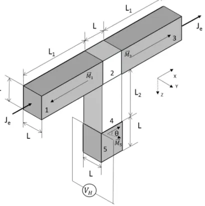
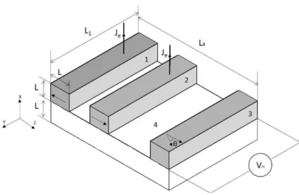
The theoretical system under investigation is depicted in Figure 1. A strong spin accumulation is generated at a first end of a spin conducting channel (labelled 2 and 4 in Fig.1) by flowing a charge current between two oppositely magnetized electrodes of pinned magnetization (labelled 1 and 3) sandwiching the first end of the spin conducting channel. This geometry is relatively similar to the one used for spin current injection in Ref 8 and 9, except for the contact area since for analytical calculation purpose, we are assuming that the spin ferromagnetic injectors 1 and 3 are in contact side to side with the spin conducting channel 2 instead of being on top of each other as in the experiments of Ref 8 and 9. Spin orbit scattering is then assumed to take place in the conductor 4 as in Ref.9. At the second end of the spin conducting channel, another magnetic electrode is introduced (labelled 5 in Fig.1) whose magnetization can be rotated.
A charge current (je) is injected between 1 and 3 along the x-direction. When the two ferromagnetic spin
injection electrodes are in parallel configuration, an antisymmetric profile of spin accumulation is generated in 2 with zero average value yielding a low spin current in the spin conducting channel 4. In contrast, as in Ref 8 or 9, when the two ferromagnetic spin injecting electrodes are in antiparallel configuration, a large spin accumulation with symmetric profile is generated in 2. The spin current generated by the gradient of spin accumulation diffuses in conductor 4 along the z-direction. Due to spin orbit scattering in channel 4, spin-up and spin-down currents are separated along the y-direction so that a
4
voltage appears across the spin conduction channel 4 in the y-direction due to ISHE. In presence of the additional magnetic electrode 5, the spin accumulation landscape and resulting spin current along the spin conducting channel is modified yielding a modulation of the ISHE voltage dependent on the orientation of the soft magnetic electrode magnetization 5. In the paper, we calculated the amplitude and variation of this ISHE voltage as a function of the angular orientation of the magnetization in the soft magnetic electrode 5. The dimensions of the various elements used in the numerical applications of the model are indicated in the caption of Fig.1.
From an experimental point of view, the magnetic electrodes 1 and 3 could be made of exchange biased IrMn/Co bilayers, 5 could be made of Permalloy and 2 and 4 of Cu or Au doped with heavy metal impurities such as Pt or Bi impurities21 (at concentration of ~ 5%) to introduce spin orbit scattering.
FIG. 1: Theoretical model of the investigated lateral spin-valve structure.
L=100 nm, L1=400 nm, L2=200 nm.
1, 3 are the ferromagnetic electrodes with antiparallel orientation of magnetizations. 2 is the first end of the paramagnetic spin-conducting channel, 4 is the paramagnetic spin-conducting channel with spin orbit scattering extending in the z direction. 5 is the soft ferromagnetic sense electrode. θ represents the relative angle between magnetizations in layers 3 and 5. Je is the charge current flow along the x
5
To calculate the spatial dependence of the ISHE voltage across the paramagnetic spin-conducting channel and its dependence on the orientation of the magnetization of sense electrode 5, the following spin-dependent transport equations were used in each material22,23:
The electrical current is a vector given by:
= − − grad + grad + grad − ( × ),
(1)
where the first and the second terms describe contributions to the current due to the electrical field and diffusion. The last term describes the ISHE.
The spin current is a 3x3 tensor given by:
!= − , − −
"#$ % % , (2)
where the first term describes the spin current due to asymmetry of conductivity for up and spin-down channels of ferromagnetic metal. The second term describes the diffusion spin current proportional to the gradient of spin accumulation. The last term is responsible for the SHE due to the spin orbit effect in the spin conducting channel (2 and 4).
The charge conservation is expressed by:
div = 0, (3)
whereas the spatial evolution of the spin current is governed by spin relaxation and spin transfer torque phenomenon:
div != − *+,- − *
.-( × ). (4)
where is the electric potential, σ the conductivity, β the parameter of spin asymmetry of conductivity,
σSH the spin Hall conductivity; a unit vector along the ferromagnet magnetization; the spin
accumulation vector, consisting of 3 components in spin space, 012 the spin diffusion length, 03 the precession length and ν the density of states at Fermi energy. The first term in (4) expresses spin relaxation and the second term is a spin-torque term. Here we should also mention that we express charge and spin currents in the same units (A/nm2). Consequently, the conductivity σ appears as prefactor in both terms
on the right hand side of equation (4). We may notice that SHE and ISHE exist in ferromagnetic electrode 5 as well, but as it was shown in Miao et al24, SHE angle in ferromagnetic (Py) is about 0.005 which is
significantly smaller than SHE angle in the paramagnetic metal (up to 0.11 in Au19). So this contribution
may give some additional, but yet small contribution to the Hall voltage in the ferromagnetic layer which will not make a significant change to the Hall voltage generated in the paramagnetic channel.
6
We may also notice that to increase the Spin Hall conductivity, it is necessary to increase the spin-orbit scattering. In this case, the spin Hall conductivity linearly increases with the amplitude of spin-orbit interaction, while spin-flip relaxation increases quadratically with this interaction. So spin relaxation increases more slowly than ISHE at small impurity concentration.
As a first step, we solved the system of equations (1)-(4), considering the spin channel 4 and electrode-detector 5 as being one-dimensional, meaning that all unknown quantities and are assumed to depend only on coordinate z. In this case, equation (4) reduces to:
;-!
; -
−
*!+,-=
(!×<)*.- (5)
The components of spin accumulation in the paramagnetic spin-conducting channel 4 can then be written:
= = >?@BCA + D?BCA (6)
= = E?@BCA + F?BCA (7)
= = G?@BCA + H?BCA (8)
Where l4 is the spin-diffusion length in the paramagnetic channel 4 and d, f, g, k, u, v are unknown coefficients.
In the ferromagnetic sense electrode 5, the components of spin accumulation can be written:
I J = K L?@ A MN (9) J = O P?@ A MQ+ OR?@M-A (10) I J = SO P?@ A MQ− SOR?@M-A (11)
with TP,R = 01203/V03R± S012R , TL = 012 , where i is the imaginary unit, KL, OP, OR are unknown
coefficients and x’, y, z’ is a coordinate system obtained from x, y, z by rotation by an angle θ around the y-axis. So the x’-axis is directed along the magnetization of layer 5.
7
Equations (6)-(11) must be complemented with boundary conditions applied for spin accumulation at the interface of layers 2/4 (z=0) and at the interface of layers 4/5 (z=z1). These continuity equations write:
> + D = XcosZ (12) E + F = 0 (13) G + H = − XsinZ (14) >?@AQBC + D?AQBC = KL?@AQMN (15) E?@AQBC + F?AQBC = OP?@AQMQ + OR?@AQM- (16) G?@AQBC + H?AQBC = SOP?@AQMQ− SOR?@AQM- (17) where X =P [\ (K]? @B-A + O^?B-A)>_ X @[ represents the value of produced by the injected current flow at the first end of the spin-conduction channel i.e. in the paramagnetic spacer 2 of the lateral spin-valve. After calculation, we derived that X is given by: X =P [\ (K]? @B-A + O^?B-A)>_ X @[ , (18) K] =b[` a Qℜd P *-e1 + ? @B-gh + Q P@a --*Q e1 − ? @B-ghi, (19) O^ =b[` a Qℜd P *-e1 + ? g B-h + Q P@a --*Q e1 − ? g B-hi, (20)
ℜ = cosh*-[ P@a*-*Q- + sinh*-[e -Q P *--+ Q -P@a -*Q- h. (21) The terms D? A BC, F? A BC, H? A BC are due to reflected spin flow at the first end of the spin conducting channel 2 caused by the presence of the sense electrode 5. For sufficiently long paramagnetic layer (L2>>l4), its influence on the value of X is negligible. Finally, this system of equations should be complemented with boundary conditions expressing the continuity of the spin current at the 4/5 interface (i.e. z=z1): k;!lm; = J(1 − R);!ln o ; (22) k;!;pm= J;!; po (23)
8
k;!Am; = J;!An o
; (24)
where k is the conductivity in paramagnetic layers 2 and 4 and J the conductivity in ferromagnetic layer 5.
Solving this system of equations (6)-(20), the expressions for the 3 components of spin accumulation were found. Finally, the expression for the ISHE voltage ∆ in the y-direction at the location of the 4/5 interface, in case of antiparallel orientation of magnetizations in electrodes 1 and 3 lying along x-axis was obtained:
∆ = rX− rPcos2Z (25)
where θ is the relative angle between magnetizations in layers 3 and 5 and
rX = P C C [ *C X?@g-BC(1 + t*C C*tu t*C(P@a-)) (26) rP = P C C [ *C X?@g-BC( C*t@ t*Ca -C*tu t*C(P@a-)) (27)
In these equations, v is the conductivity of the ferromagnetic sense electrode 5, b is the conductivity of the spin channel 4, "#b the Spin Hall conductivity of the spin channel 4, 0v the spin diffusion length in the ferromagnetic sense electrode 5.
Another interesting configuration corresponds to the case where the magnetization of electrodes 1 and 3 are set in antiparallel configuration along the z-direction i.e. parallel to the length of the spin-conducting channel while the magnetization of 5 is rotated in the (x, z) plane. The ISHE voltage is still measured at the 4/5 interface across the y-direction. It is then given by:
∆ = rRsin2Z (28) rR = P C C [ *C X?@g-BC( C*t@ t*Ca -C*tu t*C(P@a-)) (29)
where X represents the value of the spin accumulation produced by the injected charge current in the paramagnetic spacer 2 of the lateral spin-valve. The value of X is obtained in a similar way as X (equation (18)). The ISHE voltage then follows a sine variation. Indeed, when the magnetization in 5 lies
9
along the z-axis, the spin polarization, the magnetization of the 3 magnetic electrodes (1, 3, 5) and the spin current propagation direction (z-direction corresponding to the length of the spin-conducting channel) are all aligned. The ISHE voltage is then equal to zero. When the magnetization of electrode 5 is rotated away from the z-direction in the (x, z) plane, a misalignment is created, generating a back transverse spin accumulation in the spin-channel which generates a ISHE voltage in the y-direction. This voltage is maximum when the magnetization of 5 is along the x-direction.
Results and discussion:
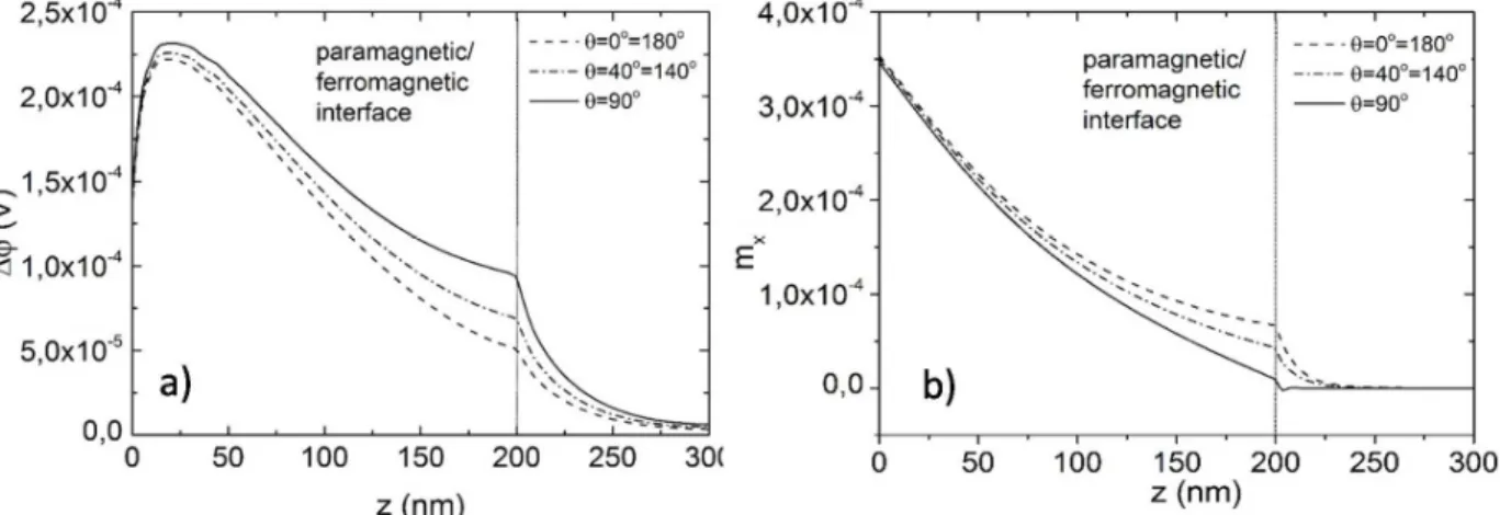
Going beyond the 1D transport assumption, to get a more accurate description of the spin transport in real 3D lateral spin-valves, we numerically solved the system of equations (1)-(4), using a finite element method with COMSOL Multiphysics® software. The magnetization of the pinned ferromagnetic electrodes 1 and 3 are again assumed to lie along the x-axis. The dependence of the ISHE voltage across the y-direction of the spin channel as a function of z-coordinate for three orientations of the magnetization of the ferromagnetic sense electrode 5 is shown in Fig.2a together with the z-profile of spin accumulation in the x direction (Fig.2b).
FIG. 2: (a) Numerical calculation of the dependence of ISHE voltage in y-direction on the z-coordinate
for different angles of magnetization of sense electrode 5. (b) Numerical calculation of the dependence of spin accumulation in the center of spin channel 4 on the z-coordinate for different angles of
magnetization of sense electrode 5. Here we assume that the magnetizations of electrodes 1 and 3 are antiparallel along the x-axis. The vertical line at z=200nm represents the interface between the spin-conducting channel 4 and the sense magnetic electrode 5.
lsf1,3,5=10 nm; ρ1,3,5=1/σ1,3,5=100 µΩ cm; β1,3,5=0.7; ν=0.1 (eV)-1; lJ=1 nm;
10
The upper indexes 1-5 refer to an appropriate layer of investigated lateral structure. The chosen parameters are just theoretical reasonable values which can be representative of a fairly resistive magnetic alloy for 1, 3, 5 (for instance a doped CoFe based alloy) and of a Cu or Ag channel for 2 and 4.
Moving away from the 2/4 interface within the spin-conducting channel, ∆ first increases then decreases. The ISHE voltage decrease as a function of z-coordinate for z>20nm is due to the gradual relaxation of the spin current on the characteristic length scale lsf assumed to be 100nm here. The increase of ∆ for
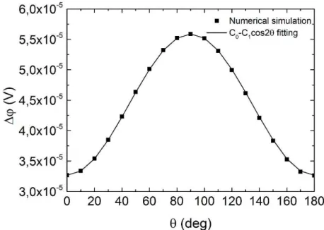
z<20nm can be ascribed to the fact that the spin-up and spin-down currents are initially spatially mixed at the first end of the spin conducting channel (in 2). These currents need to propagate over a certain distance along the spin-conducting channel 4 to allow the spin orbit scattering to separate them thus giving rise to the ISHE voltage. The modulation of the ISHE voltage by the relative angle θ between the magnetization of the sense electrode and that of the pinned ferromagnetic electrodes 1 and 3 is also clearly visible. This modulation is actually largest at the interface between the spin conducting channel and the sense electrode 5. Fig.3 shows the dependence of the ISHE voltage at this interface on the angle θ. This dependence exactly coincides with expression (25) without any noticeable deviation from cos2θ behavior. It is interesting to note that this pure cosine variation contrasts with the more complex angular variation of the CPP-GMR in metallic magnetic multilayers. Indeed in CPP-GMR, strong deviations from cosine variation of resistance versus relative angle between magnetic layers magnetization are commonly observed25. This
difference can be explained by considering that in CPP-GMR, the angular variation of the CPP resistance results from the mutual influence on the spin accumulation landscape of the magnetic configuration in all magnetic layers. On the contrary, in the present lateral spin-valve structures, the spin accumulation which is built up between the two ferromagnetic electrodes 1 and 3 is almost independent of the magnetic state of electrode 5. More exactly the value of spin accumulation is influenced by magnetic state of sense electrode 5 near its interface with paramagnetic channel 4, however this influence exponentially decreases with distance away from this interface. So the spin accumulation landscape in 2 forms a pure spin battery almost not affected by the magnetic state of the sense electrode 5. In other words, the value of initial spin accumulation X may be considered as fixed, resulting in a simpler cosine variation of the ISHE voltage than of resistance in CPP-GMR. Such simple cosine variations of non-local signal in lateral spin-valves of various geometries were experimentally observed in earlier studies10,26,27. Here, we have to mention
that the assumed current 108 A/cm2 flows only in layers 1, 2 and 3 while almost no charge current and
only small spin current flows through electrode 5. So the torque due to the spin current on the magnetization in layer 5 can be considered as negligible so that the magnetic state of 5 will not be affected by this spin current. Let us mention that in the paper28, the authors investigated the Hall voltage appearing
11
in a Hall bar structure fabricated from a non-magnetic normal metal (Au) with two separate parallel vertical wires bridged by horizontal wires of identical width. It was shown that besides Hall voltage due to ISHE, an additional Hall voltage appears due to the penetration of charge current into the horizontal wire. To check this possibility, we calculated the Hall voltage in our structure in the case σSH=0 and found
that in this case, the Hall voltage is negligibly small in comparison with the case of non-zero σSH. The
Hall voltage due to ISHE in structure presented in paper28 is proportional to the square of the Hall angle,
whereas in our structure, it varies linearly vs the Hall angle. So ISHE in our structure is significantly larger than the nonlocal Hall voltage contribution due to classical diffusive transport of quasiballistic electrons. Furthermore, in paper29, the ISHE was investigated in the system Co/Cu/YIG submitted to an applied
gradient of temperature across the system. In this case, a charge current flows in the system due to this gradient and the spin polarized part of it is mainly produced inside the dielectric YIG. It therefore weakly depends on the direction of magnetization in the Co layer. In contrast, in our system, only spin current flows in the paramagnetic channel 4 and as it was demonstrated, it strongly depends on the direction of magnetization of electrode 5.
FIG. 3: Numerical calculation of ISHE voltage in y-direction at the paramagnetic 4/ferromagnetic 5 interface versus relative angle between magnetization of sense electrode 5 and magnetization of the pinned electrode 3 when magnetizations of electrodes 1 and 3 are antiparallel along x-axis. The full line is a fit of the numerically calculated points with a cos(2θ) variation.
lsf1,3,5=10 nm; ρ1,3,5=1/σ1,3,5=100 µΩ cm; β1,3,5=0.7; ν=0.1 (eV)-1; lJ=1 nm;
12
In the previous calculation, the ISHE in the ferromagnetic sense electrode was assumed to be negligible. To check the possible influence of ISHE in the ferromagnetic sense electrode 5 on the VH output voltage,
we recalculated the dependence of Hall voltage in the vicinity of the interface 4/5 for spin Hall angle in 5 characteristic of Py (θH5 = 0.005)24 and for two values of spin Hall angle in the PM channel 4 (θH5 = 0.005
and θH4=0.1)19. The results are plotted in Fig.4. This Figure shows that the contribution to the total value
of Hall voltage VH due to ISHE in the ferromagnetic sense electrode is negligible when the spin Hall angle
in the PM channel 4 is much larger than in the sense ferromagnetic electrode 5 (Fig.4a, θH4=0.1 versus
θH5=0.005). However, it becomes noticeable when the value of the spin Hall angle in the PM channel is
13
FIG. 4: Numerical comparison of the dependence of ISHE voltage in y-direction on the z-coordinate for
different angles of magnetization of the sense electrode 5 with and without ISHE in the sense electrode . Two cases were considered: a) significantly higher spin Hall angle in 4 than in 5 (θH5 = 0.005 and
θH4=0.1). (b) Comparable spin Hall angle in 4 and 5 (θH5=θH4=0.005). In these calculations, the
magnetizations of electrodes 1 and 3 are assumed to be antiparallel along the x-axis. The vertical line at z=200nm represents the interface between the spin-conducting channel 4 and the sense magnetic electrode 5.
lsf1,3,5=10 nm; ρ1,3,5=1/σ1,3,5=100 µΩ cm; β1,3,5=0.7; ν=0.1 (eV)-1; lJ=1 nm;
lsf2,4=100 nm; ρ2,4=1/σ2,4=10 µΩ cm; θH=σsh/σ; Je=108 A/cm2.
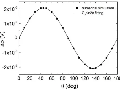
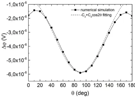
Fig.5 shows the same dependence as in Fig.3, but in the geometry where the magnetizations of electrodes 1 and 3 are antiparallel along the z-axis. The magnetization of the sense electrode 5 is still rotated in the (x, z) plane and the ISHE voltage is measured across the y-direction of the spin conducting channel at the location of the 4/5 interface. This dependence coincides with expression (28) without any noticeable deviation from sin2θ behavior. The amplitude of the variation of the ISHE voltage is comparable to that of the other configuration described in Fig.3. However, the maximum value reached by the ISHE voltage is about 4 times weaker in the configuration of Fig.5 compared to that of Fig.3.
FIG. 5: Numerical simulation of ISHE voltage in y-direction on the angle of magnetization of the sense
electrode 5 when magnetizations of electrodes 1 and 3 are antiparallel along z-axis, taken at the paramagnetic 4/ferromagnetic 5 interface.
lsf1,3,5=10 nm; ρ1,3,5=1/σ1,3,5=100 µΩ cm; β1,3,5=0.7; ν=0.1 (eV)-1; lJ=1 nm;
14
From an experimental point of view, fabricating structures such as depicted in Fig.1 with vertical interfaces may be rather uneasy. Rather, an alternative structure, which could be more easily built to investigate the above-described magnetic modulation of the ISHE voltage, is represented in Fig.6. Here, the ferromagnetic electrodes 1, 3 and ferromagnetic sense electrode 5 are all located above (or below) the paramagnetic base which serves as spin conducting channel (2 and 4). This type of device is much closer to those realized in experimental studies1-17. In this geometry, the angular dependence of ISHE voltage
(Fig.7) can be approximated with the following expression:
∆ = −rL+ rbcos2Z (27)
For this geometry, the main contribution in ISHE voltage originates from the w /wx term i.e from the vertical component (along x-axis) of the spin-current flowing from the paramagnetic base 4 to the sense electrode (labeled 3 in Fig.5). In contrast, in the previous structure of Fig.1, the main contribution to the ISHE voltage originated from w /w_ i.e. the spin current propagating along the length of the spin-conducting channel.
FIG. 6: Modeled lateral spin valve structure more suited for experimental investigation.
The dimensions of the sense electrode are typically those which would be used in read heads of hard disk drives. L=5 nm, L1=30 nm, L3=100 nm.
1,2 are the ferromagnetic electrodes with antiparallel orientation of magnetization along z-axis, 3 is the ferromagnetic sense layer, 4 represents the paramagnetic spin conducting channel with SHE. θ is the angle between magnetizations in layers 2 and 3.
The geometrical parameters chosen for the structure depicted in Fig.6 correspond to those which would be nowadays required in a readout head in hard disk drives30,31. There, the sense layer 3 would be inserted
15
in the read gap of the head next to the air bearing surface (ABS) whereas the layers 1 and 2 would be remote i.e. further in the read gap, away from the ABS. The advantage of using a sensor such as the one depicted in Fig.6 rather than a magnetic tunnel junction (MTJ) is the total thickness of the device next to the ABS. This thickness has to be as small as possible because it determines the shield to shield spacing which itself determines the downtrack spatial resolution. Since 1991 where the first magnetoresistive heads were introduced based on anisotropic magnetoresistance (AMR)31, several technologies of
magnetoresistive heads have been developed31. They were based on the current in-plane giant
magnetoresistance (CIP-GMR) of spin-valves between 1998 and 200432 and on tunnel magnetoresistance
(TMR) since 200433. Nowadays, a conventional MgO-based in-plane magnetized MTJ for Hard disk drive
has a composition of the form Ta3nm/IrMn 7nm/CoFe2.5nm/Ru0.8nm/ CoFeB2nm/MgO 1nm/CoFe1nm/Ta0.3nm/NiFe3nm/Ta3nm meaning a typical thickness of ~22nm. The above presented structure with insulating bottom and top layer could have a total thickness of about 14nm or even less compatible with the requirement for areal density of 5Tbit/in² 34. The ISHE voltage (see Fig.6) of this
sensor is represented in Fig.7. It is close to the expected form given by Eq.27 with however some deviations around 0° and 180° which can be explained as follows: When the magnetizations are aligned along z (θ=0), only the dmz/dx component gives a contribution to the Hall voltage. When the
magnetization in layer 3 (Figure 5) deviates from θ =0, a dmx/dz component also appears in addition to
the dmz/dx component. Their combined contributions at θ =10 or 170° is smaller than the contribution of
dmz/dx at θ =0 or 180° so that the maximum in the Hall voltage does not occur at 0 or 180° but at 10 or
170°. In terms of amplitude, the observed ISHE signal is rather small and would require a significant amplification before being processed in the readout channel.
Another very important point to consider is the evolution of the spin diffusion length in the spin conducting channel as a function of the channel thickness. Surface spin flip scattering seems to drastically reduce the spin diffusion length when the channel thickness becomes lower than the elastic mean free path35. For
reader applications, the spin channel thickness would have to be in the range 2 to 4nm meaning much smaller than the elastic mean free path. Indeed, if Cu is used as spin conducting channel material, the elastic mean free path in Cu is of the order of 20nm to 80nm35. This means that particular care should be
paid to minimizing spin flip scattering at Cu surfaces, otherwise the non-local signal would be significantly reduced compared to typical values calculated here or reported in experiments which are of the order of a few microvolts 1–17,19–21 .
For comparison, present TMR sensor have an output signal in the range of 20mV, 3 to 4 orders of magnitude larger than those expected from lateral spin-valves. However, what mostly matters for MR
16
heads used in recording technology is on one hand the signal to noise ratio which still need to be investigated for lateral devices and on the other hand the total thickness of the sensing part of the sensor which is reduced in the case of lateral spin-valve devices34.
FIG. 7: Numerical simulation of ISHE voltage at the paramagnetic base 4/sense layer 3 interface in the
structure of Fig.6 versus relative angle between magnetization of sense layer 3 when magnetizations of electrodes 1 and 2 are antiparallel along z-axis. The chosen parameters are chosen to be representative for device operation between 300K and 400K..
lsf1,3,5=10 nm; σ1,3,5=0.001 (Ω nm)-1; β1,3,5=0.7; ν=0.1 (eV)-1; ; lJ=1 nm;
lsf2,4=100 nm; σ2,4=0.01 (Ω nm)-1; σsh4=0.001; Je=108 A/cm2
Conclusion:
In conclusion, we have theoretically investigated the possibility to modulate the ISHE voltage in lateral spin-valves comprising a sense electrode with rotatable magnetization. The angular variation of the output signal was analytically calculated and found to follow simple cosine laws, simpler than in CPP-GMR devices, and in accordance with earlier experimental observations in other types of lateral spin-valve structures. Various geometries were considered both analytically and by finite element calculations. The device theoretically investigated in this study may be interesting as reader in hard disk drives but this statement is still uncertain. Further studies are required on one hand to minimize the decrease of the spin diffusion length due to surface scattering for very thin spin conducting channel (thickness of the order of
17
2 to 3 nm), on the other hand to evaluate the noise and signal to noise ratio of such lateral spin-valve devices. This will be the object of a subsequent paper.
Acknowledgements: This work was partially funded by the ERCEA under the ERC Advanced grant MAGICAL n° 669204. L.Vila is warmly acknowledged for fruitful discussions.
18 REFERENCES
1 T. Kimura and Y. Otani, Phys. Rev. Lett. 99, (2007).
2 T. Kimura and Y. Otani, J. Phys. Condens. Matter 19, 165216 (2007). 3 T. Kimura, T. Sato, and Y. Otani, Phys. Rev. Lett. 100, (2008).
4 E. Villamor, M. Isasa, L.E. Hueso, and F. Casanova, Phys. Rev. B 87, (2013). 5 H. Idzuchi, Y. Fukuma, and Y. Otani, Sci. Rep. 2, (2012).
6 E. Villamor, M. Isasa, L.E. Hueso, and F. Casanova, Phys. Rev. B 88, (2013).
7 P. Laczkowski, L. Vila, V.-D. Nguyen, A. Marty, J.-P. Attané, H. Jaffrès, J.-M. George, and A. Fert,
Phys. Rev. B 85, (2012).
8 W. Savero Torres, P. Laczkowski, V.D. Nguyen, J.C. Rojas Sanchez, L. Vila, A. Marty, M. Jamet, and
J.P. Attané, Nano Lett. 14, 4016 (2014).
9 V.T. Pham, L. Vila, G. Zahnd, A. Marty, W. Savero-Torres, M. Jamet, and J.-P. Attané, Nano Lett. 16,
6755 (2016).
10 G. Zahnd, L. Vila, V.T. Pham, A. Marty, C. Beigné, C. Vergnaud, and J.P. Attané, Sci. Rep. 7,
(2017).
11 L. Liu, C.-F. Pai, Y. Li, H.W. Tseng, D.C. Ralph, and R.A. Buhrman, Science 336, 555 (2012). 12 T. Yang, T. Kimura, and Y. Otani, Nat. Phys. 4, 851 (2008).
13 Y. Kajiwara, K. Harii, S. Takahashi, J. Ohe, K. Uchida, M. Mizuguchi, H. Umezawa, H. Kawai, K.
Ando, K. Takanashi, S. Maekawa, and E. Saitoh, Nature 464, 262 (2010).
14 L. Liu, T. Moriyama, D.C. Ralph, and R.A. Buhrman, Phys. Rev. Lett. 106, (2011). 15 Y. Fukuma, L. Wang, H. Idzuchi, and Y. Otani, Appl. Phys. Lett. 97, 012507 (2010). 16 T. Wakamura, K. Ohnishi, Y. Niimi, and Y. Otani, Appl. Phys. Express 4, 063002 (2011). 17 Y. Fukuma, L. Wang, H. Idzuchi, S. Takahashi, S. Maekawa, and Y. Otani, Nat. Mater. 10, 527
(2011).
18 H. Jaffrès, J.-M. George, and A. Fert, Phys. Rev. B 82, (2010).
19 J. Sinova, S.O. Valenzuela, J. Wunderlich, C.H. Back, and T. Jungwirth, Rev. Mod. Phys. 87, 1213
(2015).
20 Y. Niimi, H. Suzuki, Y. Kawanishi, Y. Omori, T. Valet, A. Fert, and Y. Otani, Phys. Rev. B 89,
(2014).
21 Y. Niimi, Y. Kawanishi, D.H. Wei, C. Deranlot, H.X. Yang, M. Chshiev, T. Valet, A. Fert, and Y.
Otani, Phys. Rev. Lett. 109, (2012).
22 S. Zhang, P.M. Levy, and A. Fert, Phys. Rev. Lett. 88, (2002). 23 M.I. Dyakonov, Phys. Rev. Lett. 99, (2007).
24 B.F. Miao, S.Y. Huang, D. Qu, and C.L. Chien, Phys. Rev. Lett. 111, (2013). 25 J.. Slonczewski, J. Magn. Magn. Mater. 247, 324 (2002).
26 T. Kimura, Y. Otani, and P.M. Levy, Phys. Rev. Lett. 99, (2007). 27 S. Nonoguchi, T. Nomura, and T. Kimura, Phys. Rev. B 86, (2012).
28 G. Mihajlović, J.E. Pearson, M.A. Garcia, S.D. Bader, and A. Hoffmann, Phys. Rev. Lett. 103, (2009). 29 D. Tian, Y. Li, D. Qu, S.Y. Huang, X. Jin, and C.L. Chien, Phys. Rev. B 94, (2016).
30 O.G. Heinonen, E.W. Singleton, B.W. Karr, Zheng Gao, Hae Seok Cho, and Yonghua Chen, IEEE
Trans. Magn. 44, 2465 (2008).
31 E.E. Fullerton and J.R. Childress, Proc. IEEE 104, 1787 (2016).
32 B. Dieny, V.S. Speriosu, S. Metin, S.S.P. Parkin, B.A. Gurney, P. Baumgart, and D.R. Wilhoit, J.
Appl. Phys. 69, 4774 (1991).
33 J.-G. (Jimmy) Zhu and C. Park, Mater. Today 9, 36 (2006).
34 Y.K. Takahashi, S. Kasai, S. Hirayama, S. Mitani, and K. Hono, Appl. Phys. Lett. 100, 052405
19