HAL Id: inria-00071423
https://hal.inria.fr/inria-00071423
Submitted on 23 May 2006HAL is a multi-disciplinary open access archive for the deposit and dissemination of sci-entific research documents, whether they are pub-lished or not. The documents may come from teaching and research institutions in France or abroad, or from public or private research centers.
L’archive ouverte pluridisciplinaire HAL, est destinée au dépôt et à la diffusion de documents scientifiques de niveau recherche, publiés ou non, émanant des établissements d’enseignement et de recherche français ou étrangers, des laboratoires publics ou privés.
UML2 as an ADL Hierarchichal Hardware Modeling
Arnaud Cuccuru, Philippe Marquet, Jean-Luc Dekeyser
To cite this version:
Arnaud Cuccuru, Philippe Marquet, Jean-Luc Dekeyser. UML2 as an ADL Hierarchichal Hardware Modeling. [Research Report] RR-5166, INRIA. 2004. �inria-00071423�
ISRN INRIA/RR--5166--FR+ENG
a p p o r t
d e r e c h e r c h e
THÈME 1
UML 2 as an ADL
Hierarchichal Hardware Modeling
Arnaud CUCCURU — Philippe MARQUET — Jean-Luc DEKEYSER
N° 5166
Arnaud CUCCURU† , Philippe MARQUET† , Jean-Luc DEKEYSER† Thème 1 — Réseaux et systèmes
Projet DaRT
Rapport de recherche n° 5166 — April 2004 — 17 pages
Abstract: Taking into account the hardware architecture specificities is a crucial step in the development of an efficient application. This is particularly the case for embedded systems where constraints are strong (real-time) and resources limited (computing, power). This approach is called co-design, and it is found more or less explicitly in ADLs (Architecture Description Languages). Many works have been done around co-design and ADLs, but no standard notation and semantics have emerged. Concerning software engineering, UML has become a recognized standard language for modeling, proving the need of users for common syntax and vocabulary to specify their applications. We believe that it would useful to use the well achieved syntax and vocabulary of UML for both applications and hardware architectures, that is to say using UML as an ADL. Our approach consists in a clear specialization of an UML subset via a the proposition of a generic profile that allows the definition of precise semantic and syntaxic rules. The generic profile can then be extended to suit the need of the user. To illustrate our subject, we give a refinement example of the profile to get relevant informations for a simulation at the TML level (Transaction Level Modeling). The modeling of the TI OMAP2410 and OMAP2420 is provided as an example.
Key-words: Architecture Description Language, ADl, UML, UML2, modeling, co-design
∗This work has been partially supported by the ITEA projet 01009, Prompt2Implementation †LIFL — Laboratoire d’informatique fondamentale de Lille, Université des sciences et technolo-gies de Lille, France
UML 2 as an ADL
Modélisation hiérarchique d’architectures
Résumé : La prise en compte des spécificités de l’architecture matérielle est un élément essentiel du développement d’applications efficaces, particulièrement dans le cas des systèmes embarqués fortement contrains (contraintes tempo-relles, contraintes de consommations électriques...). Cette approche de conception conjointe (co-design) se retrouve dans les ADL (Architecture Description Language),
même si aucune notation ou sémantique standardisée ne s’est aujourd’hui imposée. Dans le domaine du génie logiciel, UML est reconnu comme un langage standard de modélisation. Nous promouvons l’utilisation de la syntaxe et du vocabulaire d’UML pour la conception non seulement des applications, mais aussi des archi-tectures matérielles. Il s’agit d’envisager UML comme un ADL. Notre proposition est une spécialisation d’un sous-ensemble d’UML au travers un profile générique permettant la définition de règles syntaxique et d’une sémantique. Ce profile géné-rique peut ensuite être étendu en fonction des besoins particuliers de l’utilisateur. Nous illustrons cette proposition par la donnée d’un raffinement du profile pour faire figurer les informations nécessaires à une simulation au niveau transaction (TML,Transaction Level Modeling). La modélisation des 2410 et 2420 de TI est
four-nie comme exemple.
Mots-clés : Langage de description d’architecture, ADL, UML, UML2, modélisa-tion, co-design
1 Hardware Modeling and UML
The usage of an ADL permits to represent static or dynamic characteristics of a system. This system is either a software or a hardware system. For embedded systems, both system are defined: you need to co-design your application and your hardware platform in the same time with respect to specific constraints.
Concerning software engineering, UML [7] (Unified Modeling Language) has become a standard language for modeling. It does not present a particular method-ology and it can be used to model different point of view of the same model. UML 2 introduces the component notion and structure diagrams that facilitate architec-ture modeling. With deployment diagrams, UML 2 also considers hardware de-scriptions and mapping. Unfortunately, the model for applications differs from the model for hardware. The same comment applies for the mapping of an application on a particular hardware, for example a System on Chip: we want to benefit from the component notion, the hierarchical constructs of the structural and behavioral diagrams for the hardware design as well as for the software design.
We define our hardware description metamodel based on the UML 2.0 compo-nent notion. The structural specification is sufficient to generate SystemC [8] code to produce a TLM (Transaction Level Modeling) simulation once the mapping of an application on this hardware model is achieved.
1.1 Related Works
Several proposals, emerged from the OMG world or not, introduce hardware mod-eling techniques and/or concepts. Only a few ones are “sold” as ADLs.
AADL [2] (Avionics Architecture Description Language) is the only proposal which clearly advocates the use of UML as an ADL. This language is based on MetaH. It is used to describe the structure of an embedded system as a gathering of software and hardware components. It can describe both functional (data inputs and outputs) and non functional (such as timing) aspects of components. A UML profile for AADL (based on UML 2) is under standardization, and will be soon submitted to the OMG. Concerning the hardware modeling part of this proposal, four concepts are introduced: memory, processor, bus and device. We will see later
in this paper that our proposal is not semantically far from this one. However, the goal of hardware modeling (called platform) in AADL is not the same as ours. The platform specification is more or less used to apply schedulability and fault toler-ance analysis verification tools (that is to say to verify that a software associated to one platform meets the requirements that the system must satisfy), whereas the
4 A. Cuccuru, Ph. Marquet & J.-L. Dekeyser
tools we plan to use are rather optimization tools (for mapping of computing, data, and communications). Moreover, we can’t clearly see in the specification of the language how the hardware concepts can be composed and/or assembled.
The UML SPT Profile [6] (Scheduling, Performance, and Time analysis) is an UML 1.x OMG standard profile for embedded systems modeling. It introduces var-ious hardware (or more generally platform) modeling concepts and an interesting resource classification according to three criteria: purpose (processor,
communica-tion and device),activeness (a resource is active when it is able to generate stimuli,
and passive when it is only able to react when prompted by stimuli), andprotection
(a resource is protected when the access to services it offers is restricted according to some control access policy). However, the profile gives no clear orientation and methodology on the way it can be used. Moreover, the underlying execution model (a resource is acquired and then released) is too restrictive and unfortunately does not suit our needs.
HaSoC [4, 5] (Hardware and Software Objects on Chip) is a platform-based design methodology using UML to represent high-level structure and behaviour of the hardware architecture model of an application platform. The hardware ar-chitecture model of HASoC distinguishes general-purpose hardware (processors, memory), programmable logic (FPGAs), fixed-function (custom) hardware, and in-terconnection elements. This model enables to generate SystemC code for simula-tion and particularly for hardware synthesis. For our purpose, distincsimula-tion between programmable and non programmable units is not necessary1, as hardware syn-thesis is not one of our goal. Moreover, this model doesn’t seem to exploit hierar-chical capabilities offered by UML 2.
The SLOOP [11] (System Level design with Object-Oriented Process) design process integrates a methodology based on UML for both SoC modeling and per-formance evaluation at system level. The hardware model proposed is similar to those previously presented: it proposes hardware elements such as processors, memories, buses and hardware devices. However, the hardware architectures are modeled via deployment diagrams, with various stereotypes applied to “Nodes”. This choice has the benefit of being simple and relatively natural for people coming from the UML world. Indeed, deployment diagrams are used to coarsely describe execution platforms for applications. But we believe that deployment diagrams are too restrictive to model architectures (no hierarchy, no encapsulation via ports and interfaces, no behavior description...), and that the same model must be used for both hardware and software.
1As we’ll see later, we just tell which functions can be executed by a processing unit
1.2 Proposal
Our approach consists in a clear specialization of an UML subset for which we can define precise syntactic and semantic rules. This prevents from all kind of ambigu-ities in the model2.
The abstract syntax of our model is described by a MOF metamodel defined as an extension of the UML 2 metamodel. The metamodeling brings a set of tools which will enable us to specify our application and hardware architecture models using UML tools, to reuse functional and physical IPs, to ensure refinements be-tween abstraction levels via mapping rules, to ensure interoperability bebe-tween the different abstraction levels used in a same codesign, and to ensure the opening to other tools, like verification tools, thought the use of standards. The concrete syn-tax is defined by a profile for UML 2. This profile is, for the moment, only based on UML 2 class diagrams and internal structure diagrams3. In this paper, we focus on the description of the profile(there is almost a “one to one” equivalence between concepts introduced in the metamodel and stereotypes introduced in the profile). The generic rules and concepts are described in a generic part of the profile. This generic elements are then refined via an extension of the profile to fit to the needs of the user (documentation, simulation at various abstraction levels, optimization...).
The first part of the paper summaries the so-called “Y model approach” [1], and describes the generic part of the profile, focusing on the set of “basic blocks” that define the syntax and semantics of our hardware architecture model. Therefore, we propose a classification, at the same time both functional and structural, in order to identify each kind of components4of our model. Then, we specify the construction rules which govern components assembling and composition.
The second part of this document shows how an extension of the profile can be used to refine the “basic blocks”, in order to produce models suited to a par-ticular use. For that, we give an extension of the used profile to gather relevant informations of a simulation at a TLM level in an environment such as SystemC. As a conclusion, we illustrate our subject with a case study: the TI OMAP2410 and OMAP2420 [10].
2This restriction does not mean that the usage of the other UML elements are forbidden. It only means that all the elements added by a user in a model will not be taken into account by tools which exploit the profile.
3We are investigating the introduction of activity diagrams, and possibly state diagrams, to model hardware architecture behavior
6 A. Cuccuru, Ph. Marquet & J.-L. Dekeyser
2 Y Model Approach
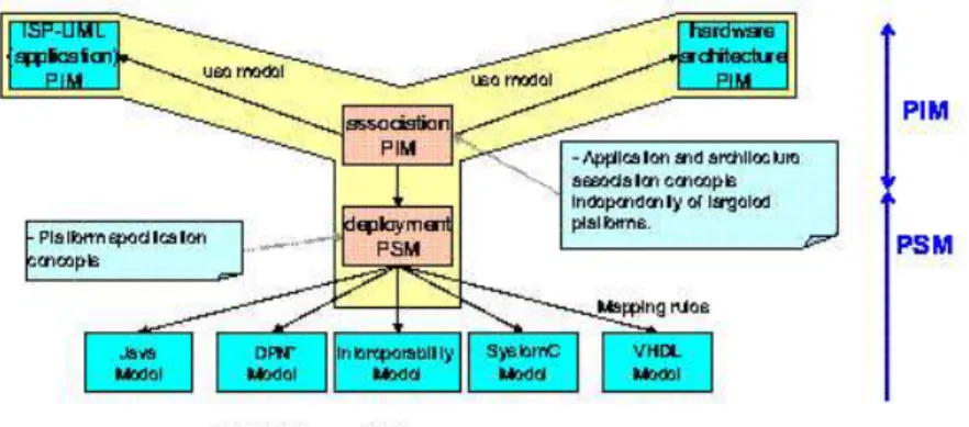
Our proposal is partially based upon the “Y-chart” [3] concepts. A clear distinci-tion is made between applicadistinci-tion and hardware, which are related via an explicit mapping.
Figure 1: Y Model Approach
The application and hardware architecture are described by different metamod-els. Some concepts handle within these two metamodels are similar in order to unify and so simplify their understanding and use.
The proposed methodology is to separately design the two models for the ap-plication and the hardware architecture (maybe by two different people). At this point, it becomes possible to map the application model on the hardware architec-ture model. For this purpose we introduce a third metamodel, the so-called associ-ation metamodel, to express the associassoci-ations between the functional components of the application model and the hardware components of the hardware model. This third metamodel imports the first two metamodels.
3 Hierarchical Hardware Architecture Model
We present here the different hardware components that we introduce in our model, and we give the rules on the way to compose and assemble them with each other.
The hardware components represent abstractions of physical hardware archi-tecture elements. A hardware component owns an interface materialized by its
ports, and a structure defined by an assembly of components via an internal struc-ture diagram.
3.1 Resource Classification
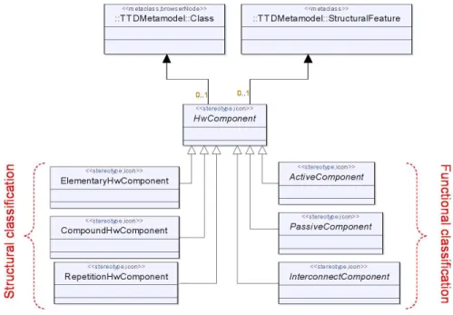
We propose to classify the resources according to two criteria: a functional criterion, and a structural criterion (Fig. 2). Each resource is characterized by a composition of this two criteria. In UML, it comes to apply two stereotypes to each component.
Figure 2: Resource classification
IFunctional Classification We identify three kinds of function for a component (three stereotypes in UML): a component can be either passive, active, or for inter-connection.
“PassiveHwComponent” A passive component symbolizes a resource which has
the function of supporting data. Typically, we find in this category elements such as RAMs, ROMs, sensors, or actuators.
8 A. Cuccuru, Ph. Marquet & J.-L. Dekeyser
“ActiveHwComponent” An active component symbolizes a resource which has
the function or reading or writing into passive resources. It may modify, or not, the data. This category includes elements such as CPUs or DMAs. It also includes more coarse-grained elements, such as a SMP node inside a parallel machine.
“InterconnectHwComponent” An interconnection resource connects active and
passive components, or active and active in the case of a distributed memory architecture. This category includes element as simple as a bus, or as complex as an omega interconnection network.
IStructural Classification The structural classification is used ease introspection of models and, as a consequence, automatic or manual exploitation of gathered data (for example to optimize the mapping of an application on a hardware archi-tecture). We identify three kinds of structure for a component (three stereotypes in UML): a component may be either elementary, passive, or for repetition.
“ElementaryHwComponent” An elementary component is a component without
an internal structural description. For example, it could be used in the case where we have an hardware IP for this component, or in the case where we don’t want to model the component more finely.
“CompoundHwComponent” A compound component is a component with an
in-ternal structure description. A compound component can represent an “ex-ecutable architecture” (fully defined architecture) or a part of an architecture that will be reused in other contexts. A compound component may be defined with several hierarchy levels: a compound component may be described as the gathering of other “sub” compound components. The benefits of compo-sition are numerous, and they are not specific to our model: encapsulation of structural details not needed at a given hierarchical level, reuse or repeti-tion (in the case of a “RepetitionHwComponent”) of predefined blocks to
model other architectures...
“RepetitionHwComponent” A repetition component5is a particular case of the
compound component. The repetition component structure contains a regu-lar repetition of a single component. This kind of component is well suited to the modeling of massively parallel architectures and is motivated by the recent introduction of such architectures in the design of SoC such as the pic-oChip PC101 [9].
5This kind of component is part of a work in progress and will not be detailed in this paper.
3.2 Construction Rules
The construction rules (that is to say the composition and assembling rules) of our model are based on UML 2.0 rules. From generic UML rules, we define coherent rules for the possible direction of ports (“required” or “provided”) according to the function of each component (“active”, “passive” or “interconnection”). Then, we propose rules for components assembling, based on rules given for ports direction. We also lightly modify the semantic of connection concept, but we remain coherent with definition given in UML 2 specification. Finally, we give rules concerning component composition.
IAssembling Rules Defined in UML 2 The components are linked together via connectors. The ports materialize the connection points. One or more required or provided interfaces are associated to each port. Two ports can be connected only if they have compatible interfaces, and if one port is “required”6, and the other is “provided”6.
The methods associated to each interface represent services. A component with a required port is able to emit services requests to its environment, whereas a com-ponent with a provided port provides a set of services to its environment.
IPorts “direction” We use assembling rules defined in UML to restrict possible directions of ports (required or provided) associated to each kind of components of our architecture model.
A passive component only owns provided ports, as it can only propose services for data support (read/write) to active components. An active component typi-cally owns required ports, as it can emit read or write services requests to passive components. It can also own provided ports to receive requests emitted by other active components, for example in the case of a distributed memory architecture. An interconnection component owns required and provided, as it has the function of linking active and passive components, or active and(Fig. 5) active components. IAssembling Rules Respecting rules previously mentioned, two passive com-ponents can not be connected together (on both sides, there are only provided ports). We add the constraint that all connections between active and passive com-ponents or between active and active comcom-ponents must be done via an intercon-6A “required port” refers to a port with a required interface , and a “provided port” refers to a port with a provided interface.
10 A. Cuccuru, Ph. Marquet & J.-L. Dekeyser
nection component. This constraint enables to ease and systematize the parsing of models. Moreover, a clear identification of the interconnection resources enables to associate properties to these resources (such as bandwidth, or latency).
IConnections Semantics Services associated to ports are implicit according to the function of the component and the definition we gave of these functions (the active components require read/write services to passive components via inter-connection components). As a consequence, an incomplete model in the standard UML formalism (that is to say with no interfaces associated to ports) can be inter-preted without ambiguities in the context of our profile. The user of the profile is free to add the interface suited to the case he is modeling.
Connections between ports are interpreted as potential data paths offered by architecture, more than paths for services exchanges. This semantics is close to the semantics of connections between modules in SystemC.
In our case, the association of interfaces to ports in a hardware architecture is a way to refine its specification according to application mapped on this architecture. IComposition Rules A passive compound component may only contain other passive components. A active compound component can only contain other inter-connection components. An active component can contain all kinds of component. The top level component in the hierarchy is necessarily a active compound (or repe-tition) component. By this way, the parsing of an architecture consists in a traversal of active compound or repetition components.
4 A Profile Refinement for TLM Level Simulation
In this section, we show a refinement of the generic profile designed to get rele-vant informations from a simulation at a TLM level, such as execution time, load of interconnection elements, load balancing of active elements... The profile refine-ment consists in extending stereotypes defined in the generic part by adding them properties. First of all, we describe data types associated to properties of various modeling elements. Then, we show successively a refinement for active elements, for passive elements, and finally for interconnection elements.
4.1 Data Types
Data types described here are used to type properties added to various refined model elements:
TimeExpression is an expression representing a duration("13ns")
FrequencyExpression is an expression representing a clock frequency
("1.2MHz")
CapacityExpression is an expression representing a capacity("16Mo") BandWidthExpression is an expression representing a bandwidth("3.5Go/s")
4.2 Active Component Refinement
Figure 3: Active component refine-ment
To refine the concept of active component, we introduce two kinds of components: “CPU” and “DMA” (Fig. 3). These
compo-nents extend (in a UML point view, but par-ticularly in a semantic point of view) the definition of the active component.
I “CPU” Component A CPU represents a resource able to read and write in pas-sive resources, with or without data mod-ifications. It also symbolizes a resource able to execute functions defined in the applica-tion model. It is potentially able to execute all functions, except if the list of functions is explicitly restricted7. CPU is a generic
term gathering CPUs (strict meaning), DSPs, or even FPGAs (i.e. all kind of pro-grammable or not propro-grammable resource able to realize a computation on data). A CPU is characterized by four attributes:
frequency: FrequencyExpression. This property represents the clock
fre-quency of the CPU. For example, it can be used to determin the execution duration of a function, in the case where the number of cycles necessary to execute this function on this CPU is known.
7The way to restrict a list of executable functions is not described here. This problem is rather related to the association model.
12 A. Cuccuru, Ph. Marquet & J.-L. Dekeyser
wordSize: Integer. This property represents the size of the words handled by
the CPU. The size expression unit is the bit.
dataCache: CapacityExpression. This property represents the size of the
data cache of the CPU.
instructionCache: CapacityExpression. This property represents the size
of the instruction cache of the CPU.
I“DMA” Component A DMA is characterized by its number of channels and by the policy it uses: whether it is based on cycle-stealing or not.
4.3 Passive Component Refinement
To refine the concept of passive component, we introduce three kinds of compo-nent: “Memory”, “Sensor” and “Actuator” (Fig. 4). These components extend
(in a UML point view, but particularly in a semantic point of view) the definition of the passive component.
Figure 4: Passive component refinement
I“Memory” Component A memory has the function of supporting data. It is characterized by six attributes:
capacity: CapacityExpression. This property represents the size of the
memory.
latency: TimeExpression. This property represents the latency related to a
memory access. The value is expressed in time, and not in cycles, in order to make easier the reuse of memory component for several architecture mod-elings, or in the case of heterogeneous architectures (several kinds of CPU accessing the same memory component).
readBandWidth: BandWidthExpression. This property represents the read
bandwidth of the memory.
writeBandWidth: BandWidthExpression. This property represents the write
bandwidth of the memory.
wordSize: CapacityExpression. This property represents the size of a
mem-ory word.
burst: Integer. This property represents the number of memory word
col-lected when an access in burst mode occurs.
I“Sensor” Component A sensor represents a resource able to periodically catch data from its environment, and put it at hardware architecture disposal. Sensors are classified in the category of passive elements, in the way that they can be consid-ered as read only memories. A active element can periodically get (read) data to compute or move from it. A sensor is characterized by two attributes:
latency: TimeExpression. This property represents the latency related to a
read access.
readBandWidth: BandWidthExpression. This property represents the read
bandwidth of the sensor.
I“Actuator” Component An actuator is the opposite of a sensor, that is to say
a resource that provides data from the hardware architecture to its environment. Actuators are classified in the category of passive elements, in the way that they can be considered as write only memories. An active component can periodically give (write) data to it. An actuator is characterized by two attributes:
latency: TimeExpression. This property represents the latency related to a
write access.
writeBandWidth: BandWidthExpression. This property represents the write
14 A. Cuccuru, Ph. Marquet & J.-L. Dekeyser
4.4 Interconnection Component Refinement
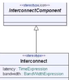
Figure 5: Interconnection compo-nent refinement
To refine the concept of interconnection com-ponent, we introduce one kind of component: “Interconnect” (Fig. 5). This component
ex-tends (in a UML point view, but particularly in a semantic point of view) the definition of the interconnection component.
I “Interconnect” Component The
inter-connect is not more precise semantically than the interconnection component defined in the generic part of the profile. It’s just an intercon-nection enriched with properties used for a sim-ulation at a TLM level. It is characterized by two attributes:
latency: TimeExpression. This property represents the latency related to an
access to the interconnection component.
bandWidth: BandWidthExpression. This property represents the bandwidth
of the interconnect.
5 Modeling examples: The TI OMAP2410 and OMAP2420
We present in this section two modeling examples. Specifications are deliberately not complete, and are just introduced for an illustration purpose. We illustrate the use of various modeling elements (refined or not) of our model, and the use of the inheritance mechanism of UML to define an hardware architecture by extension of another one.The OMAP2410 and OMAP2420 processors are based on OMAP2 “All-in-One Entertainment” architecture [10]. They are designed to be used into smart-phones and portable media devices. They support high-end features such as multi-megapixel cameras, hifi music with 3D sound effects, high-speed wireless connec-tivity and more.
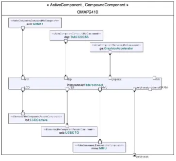
The OMAP2410 processor (Fig. 6) consists of an ARM11 that handles the operat-ing system tasks and a TMS320C55 that works on the audio and video applications. It also contains additional features such as a hardware engine for three-dimensional images, a MMU (memory management unit), and interfaces to LCD/Camera, USB
Figure 6: OMAP 2410 Structure
devices, and peripherals. Communications are made via a low-latency intercon-nection component.
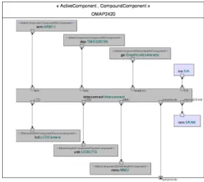
The OMAP2420 processor (Fig. 8) is an extension of the OMAP2410. It extends the features of the 2410 with an IVA (Imaging Video Accelerator) and a 5 Mbit SRAM supporting a VGA display. As illustrated in Fig. 7, the OMAP2420 inherits the definition of the 2410.
6 Conclusion
We have shown how we use UML 2 as an ADL, focusing on the hardware model of our approach. The model we have presented enables a description of hardware architectures at a high abstraction level. This model is implemented in a UML pro-file. This profile introduces generic concepts, with clear semantic and syntaxic ba-sis, that can be refined for particular use. We gave an example of profile refinement to get relevant informations from a simulation at a TLM level, and we illustrated our subject with the modeling of the TI OMAP2410 and OMAP2420.
16 A. Cuccuru, Ph. Marquet & J.-L. Dekeyser
Figure 7: Inheritance link between
OMAP 2410 and OMAP 2420 Figure 8: OMAP 2420 Structure
This is only the first step of our approach. We are currently working on mech-anisms to express repetition of architectural elements. It enables for example to easily model regular hardware architectures such as hypercubes, or complex inter-connection networks such as Omega networks. The repetitions are expressed in the context of the “RepetitionHwComponent”, with mechanisms similar to ones
used in the application model to express data parallelism via dependency expres-sions.
Moreover, we plan to soon introduce behavioral descriptions of hardware com-ponents. Typically, such informations would be taken into account in our simula-tion environment. For example, it would be useful the describe the behavior of a shared interconnect element (priority policy) to get informations about latency.
References
[1] Cédric Dumoulin, Pierre Boulet, Jean-Luc Dekeyser, and Philippe Marquet. UML 2.0 structure diagram for intensive signal processing application specifi-cation. Research Report RR-4766, INRIA, March 2003.
[2] Peter H. Feiler, Bruce Lewis, and Steve Vestal. The SAE avionics architecture description language (AADL) standard : A basis for model-based architecture-driven embedded systems engineering. In RTAS 2003 Workshop on Model-Driven Embedded Systems, May 2003.
[3] D. D. Gajski and R. Kuhn. Guest editor introduction: New VLSI-tools. IEEE Computer, 16(12):11–14, December 1983.
[4] Peter Green and Martyn Edwards. The modeling of embedded systems us-ing hasoc. InDesign, Automation and Test in Europe Conference and Exhibition (DATE’02), Paris, France, March 2002.
[5] Peter Green and Martyn Edwards. Platform modeling with UML and systemc. InForum on specification and Design Languages (FDL’02), September 2002.
[6] Object Management Group, Inc., editor. (UML) Profile for Schedulability, Perfor-mance, and Time Specification. http://www.omg.org/cgi-bin/doc?ptc/
2002-03-02/, May 2002.
[7] Object Management Group, Inc., editor. (UML 2.0): Superstructure Draft Adopted Specification. http://www.omg.org/cgi-bin/doc?ptc/ 03-07-06/, July 2003.
[8] Open SystemC Initiative. SystemC. http://www.systemc.org/, 2002.
[9] picoChip. PC101 and PC102 datasheets. http://www.picochip.com/
technology/picoarray, 2003.
[10] Texas Instruments. OMAP 2 architecture. http://focus.ti.com/docs/ general/splashdsp.jhtml?&path=templatedata/cm/%splashdsp/
data/omap2, 2004.
[11] Qiang Zhu, Akio Matsuda, Shinya Kuwamura, Tsuneo Nakata, and Minoru Shoji. An obect-oriented design process for system-on-chip using UML. In
Proceedings of the 15th international symposium on System Synthesis, pages 249–
Unité de recherche INRIA Futurs
Domaine de Voluceau - Rocquencourt - BP 105 - 78153 Le Chesnay Cedex (France)
Unité de recherche INRIA Lorraine : LORIA, Technopôle de Nancy-Brabois - Campus scientifique 615, rue du Jardin Botanique - BP 101 - 54602 Villers-lès-Nancy Cedex (France)
Unité de recherche INRIA Rennes : IRISA, Campus universitaire de Beaulieu - 35042 Rennes Cedex (France) Unité de recherche INRIA Rhône-Alpes : 655, avenue de l’Europe - 38330 Montbonnot-St-Martin (France) Unité de recherche INRIA Rocquencourt : Domaine de Voluceau - Rocquencourt - BP 105 - 78153 Le Chesnay Cedex (France)
Unité de recherche INRIA Sophia Antipolis : 2004, route des Lucioles - BP 93 - 06902 Sophia Antipolis Cedex (France)
Éditeur
INRIA - Domaine de Voluceau - Rocquencourt, BP 105 - 78153 Le Chesnay Cedex (France)
http://www.inria.fr