HAL Id: hal-00605297
https://hal.archives-ouvertes.fr/hal-00605297
Submitted on 1 Jul 2011
HAL is a multi-disciplinary open access
archive for the deposit and dissemination of
sci-entific research documents, whether they are
pub-lished or not. The documents may come from
teaching and research institutions in France or
abroad, or from public or private research centers.
L’archive ouverte pluridisciplinaire HAL, est
destinée au dépôt et à la diffusion de documents
scientifiques de niveau recherche, publiés ou non,
émanant des établissements d’enseignement et de
recherche français ou étrangers, des laboratoires
publics ou privés.
Dynamic tests on a cohesive and frictional material.
Influence of high pressure and high strain rate on
compaction and shear.
Patrice Bailly, Franck Delvare, Maxime Biessy, Didier Picart
To cite this version:
Patrice Bailly, Franck Delvare, Maxime Biessy, Didier Picart. Dynamic tests on a cohesive and
frictional material. Influence of high pressure and high strain rate on compaction and shear.. 9th
International conference on the mechanical and physical behaviour of materials under dynamic loading,
Sep 2009, Brussels, Belgium. pp.213-218, �10.1051/dymat/2009029�. �hal-00605297�
Dynamic tests on a cohesive and frictional material.
Influence of high pressure and high strain rate on
compaction and shear.
P. Bailly
1, F. Delvare
1, M. Biessy
2, D. Picart
21
ENSI Bourges, Institut PRISME, F-18020 Bourges
2
CEA, DAM, Le Ripault, F-37260 Monts
Abstract. Many of aggregate composites are made of small size particles mixed with a highly compliant
rubbery polymer. When the loading leads to high pressures, the behaviour gets closer to this of cohesive, frictional, and compactable materials. When this kind of material is subjected to an impact, the loading domain is the case of high pressure (from 100 to 1000 MPa) and high strain rate (roughly 1000 s-1). An experimental study is led by using the technique of the SHPB. The specimens are small cylinders placed in a ring which creates a passive confinement by opposing to the radial displacements. The instrumentation of the ring allows to estimate the radial stress and the radial displacement. The main point is that it makes possible the follow-up of the spherical and deviatoric parts of the stress and strain tensors during the test, without restrictive hypothesis on the behaviour of the material. The results show a high sensitivity to the strain rate. The stresses evolutions show that the frictional phenomenon is sensitive even under high pressures.
1. INTRODUCTION
The aim of this study is to observe experimentally the behaviour of a material under high pressure and high strain rate. The material is an aggregate composite made of small size particle mixed with a highly compliant rubbery polymer [1]. The load domain corresponds to the one which is reached during shocks or during impacts of missiles (from 100 to 1000 MPa for the pressure and roughly 1000
s-1 for the strain rate). The material peculiarities determine the loading path which it will be desirable
to follow. Confined compression tests are defined and are obtained using a Split Hopkinson Pressure Bar (SHPB) device. The confinement is made by metallic rings. The dimensions and the constitutive materials of the ring are defined to obtain the wished loading path.
2. THE EXPERIMENTAL DEVICE
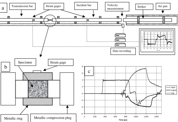
The SHPB device, also called Kolsky's apparatus, is a commonly used experimental technique in the study of constitutive laws of materials at high strain rates. Dynamic compression testing under confinement pressure is not so frequent. For low confinement pressures, experimental data are obtained using a SHPB device combined with a pressure cell [2], [3], [4], [5]. This technique does not allow high pressures. Following a few authors [6][7], we propose a test where the specimen is confined by an instrumented metallic ring and axially loaded by a SHPB system (figure 1 a) specially designed for this purpose. This system is composed of long input and output bars with a short
specimen placed between them. When the striker impacts the input bar at its free end a compressive longitudinal "incident" wave is created. Once this incident wave reaches the interface between the specimen and the bar, a reflected pulse appears in the input bar and a transmitted one in the output bar. Strain gages are glued on the input and output bars and allows to record these three basic waves. The bars, made of hard steel (1000 MPa), have a 20 mm diameter. The input bar is 3 m long, the output bar is 2 m long and the striker is 1.2 m long. The length of the striker and the strain gages positions allow test duration of 400 µs. Forces and particle velocities at both faces of the specimen can be deduced from incident, transmitted and reflected waves. A complete data processing of the waves is used, including wave dispersion correction and an assisted time shifting based on the elastic transient response of the specimen. This precise data processing is especially important for testing brittle materials that cannot support large strains without damage [8]. An additional transversal gage is glued on the metallic ring (figure 1b). This gage measures the radial expansion of the ring. From this measurement and with the assumptions of an elastoplastic behaviour of the metallic ring, the lateral pressure on the specimen can be estimated.
-6 -4 -2 0 2 4 6 8 0 200 400 600 800 1000 1200 1400 Time (µs) input output ring
Figure 1.The SHPB test system (a), the specimen confinement device (b) and typical records of the input and
output waves and of the extension strain of the metallic ring (c).
In order to exploit the tests, we use the assumption of stresses homogeneity in the specimen. The homogeneity of the axial stress is checked since we have the same forces at the two ends of the sample. By opposition to simple compression tests on brittle materials, the inertia effects are removed by the confinement ring. In present tests, we have a strong confinement and a small radial expansion of the ring, in particular when the ring keeps an elastic behaviour. The stresses evolutions are increasing and monotone. It can then be assumed that localisation will not occur. Stress-strain relations and a loading path can then be derived.
Strain gage Specimen
Metallic ring Metallic compression plug
b
-15 -10 -5 0 5 10 15 800 1000 12001400 1600 1800 2000 22002400 Temps (µs) "D é fo rm a ti o n" (V )Transmission bar Strain gages Incident bar Velocity Striker Air gun
measurement
Data recording
a
3. THE LOADING PATHS
To precise the stress state, we shall use the pressure P, or hydrostatic stress, and Q, the octahedral shear stress (1). The subscript 1 denotes the axial direction of the specimen and the subscript 2 denotes the transverse direction.
σ
=
trace
3
1
P
S
=
σ
−
P
ℑ
S
:
S
3
1
Q
=
(
)
(
)
σ
−
σ
=
σ
+
σ
=
2 1 2 13
2
Q
2
3
1
P
(1)Triaxial quasi-static tests on the material were worked out. They allow to determine a shear resistance criterion (2) and an 20 ° internal friction angle. The usual values of the internal friction angle for brittle materials is included between 30° and 40° . The lower value is probably due to the highly compliant rubbery polymer.
(
MPa
)
P
25
,
0
12
Q
=
+
C
=
10
MPa
ϕ
=
20
°
(2)This material has also a high Poisson ratio (about 0.42) and its Young modulus E is equal to 2 GPa. If we confine the cylindrical specimen with a metallic ring, the ratio between Young moduli is such that the radial displacement of the ring is negligible. The stress state is very close to the oedometric state (uniaxial strain). With the characteristic values of the material, the shear resistance criterion ( 3 ) can not be reached by the oedometric loading path.
ν
+
ν
−
=
1
2
1
P
2
Q
(
Q=0,22P)
(3)When the ring behaviour remains elastic, the transversal stress grows faster than when the ring begins to plastify. When the ring is completely plastified, the transversal stress remains constant (this value is
denoted by pc) and the corresponding loading path is parallel to the simple compression one.
On figure 2, the line OA corresponds to the beginning of the test when the ring remains elastic. The line AB corresponds to the end of the test, when the ring is totally plastified. The line OC is the loading path corresponding to a simple compression test. The beginning of our test is close to the simple compression (the dotted line shows the real loading path). In fact, there is always a very small space between the specimen and the ring. So, the beginning of the test is close to the simple compression (the dotted line shows the real loading path). In order to obtain several values of the confinement pressure, different rings are used. They are made of steel or of brass with different thicknesses (figure 2b).
Figure 2. The loading paths (a). A ring made of steel and a ring made of brass (after the test) (b).
P
Q
Criterionp
c Elastic ring Plastic ring O A B C4. RESULTS
In this section, two representative tests results are presented. The first test is realised with a ring made of steel. The thickness of the ring is 5 mm. The confinement pressure imposed at the end of the test is
620 MPa so that the ring is plastified. During this test, the strain rate reached the value of 1300 s-1.
The figure 3a presents the evolution of the axial stress and of the radial stress versus the axial strain. The figure 3b represents the state stress in the P-Q diagram. We can notice, at the beginning of the test, a disturbance due to a short phase of simple compression caused by the small gap between the specimen and the ring. During the elastic behaviour phase of the ring (when the axial strain is less than 0.15), the ratio between radial stress and the axial stress is equal to 2/3. This ratio depends on the specimen Poisson ratio which is equal to 0.42.
0,0E+00 2,0E+08 4,0E+08 6,0E+08 8,0E+08 1,0E+09 1,2E+09 0,00 0,04 0,08 0,12 0,16 0,20 Axial strain S tr e s s ( P a ) 0,0E+00 5,0E+07 1,0E+08 1,5E+08 2,0E+08 2,5E+08
0,E+00 2,E+08 4,E+08 6,E+08 8,E+08 Pressure (Pa) Q ( P a )
Figure 3. Dynamic compressive test with a steel ring with 5 mm in thickness. Axial and radial stresses versus the
axial strain (a) and stress state in the P-Q diagram (b).
The second test is realised with a ring made of brass. The thickness of the ring is 2 mm. The confinement pressure imposed at the end of test is 150 MPa and the ring is plastified. During this test,
the strain rate reached the value of 1200 s-1. The figure 4a presents the evolution of the axial stress and
of the radial stress versus the axial strain. The figure 4b represents the state stress in the P-Q diagram. We can also notice, at the beginning of the test, a disturbance caused by the small gap between the specimen and the ring. The plastic behaviour phase of this ring is reached for a lower hydrostatic pressure and allows a greater plastic deformation of the specimen than the one obtained in the previous test. 0,0E+00 1,0E+08 2,0E+08 3,0E+08 4,0E+08 5,0E+08 6,0E+08 0,00 0,05 0,10 0,15 0,20 0,25 0,30 0,35 0,40 Axial strain S tr e s s ( P a ) 0,0E+00 5,0E+07 1,0E+08 1,5E+08 2,0E+08
0,0E+00 5,0E+07 1,0E+08 1,5E+08 2,0E+08 2,5E+08 3,0E+08
Pressure (Pa) Q (P a )
Figure 4. Dynamic compressive test with a ring made of brass with a 2 mm thickness. Axial and radial stresses
versus the axial strain (a) and stress state in the P-Q diagram (b).
σ
1σ
1σ
2σ
2a
b
a
b
Other tests were also worked out with the same device and with the same specimen. Only the thickness of the rings and the impact velocities were changed. These parameters have an influence on
the strain rate and on the confinement pressure pc. It is well known that the strain rate has an influence
on the octahedral shear stress Q. The parameters of the tests and the results are gathered in table 1. In figure 5, each test is also represented in the P-Q diagram by a little star. For the cases C and D, the line and the dotted line correspond to the quasi-static test
Table 1. Parameters of the tests
Ring (thickness) Strain rate (s-1) p
c (MPa) P (MPa) Q (Mpa)
A1 A2 No ring 0 500 0 4 30 13 90 B Brass (1 mm) 1000 80 140 80 C1 C2 C3 C4 Brass (2 mm) 0 1100 1200 1300 150 200 270 275 270 60 110 180 140 D1 D2 D3 Brass (3 mm) 1000 1400 1400 240 340 360 380 140 160 200 E1 E2 E3 Steel (5 mm) 0 1300 1600 620 750 750 850 110 190 340 0 100 200 300 0 100 200 300 400 500 600 700 800 900 1000 Pressure (MPa) Q ( M P a )
Figure 5. Results of several tests in the P-Q diagram.
A B C D E
5. CONCLUSION
Confined compression tests were worked out using a classical SHPB device. The passive confinement was realized using a ring made of an elasto-plastic material. The tested material is an aggregate composite made of small size particle mixed with a highly compliant rubbery polymer. The material presents an internal friction angle (roughly 20°) which decreases when the pressure becomes higher. This angle is small compared with that of concrete or stones (between 30° and 40 °). This technique allows us to reach a large loading domain which depends on the ring thickness and on its constitutive material (steel or brass). With a steel ring, it is possible to reach a high level of hydrostatic pressure, while with a brass ring, it is possible to reach a large plastic deformation of the specimen but a weaker hydrostatic pressure. One interest of this experimental device is to be able to separate, in the dynamic behaviour, the spherical part and the shear part of the stress tensor. We can notice that the material strength strongly depends on the strain rate. This sensitivity seems rather connected to the shear strain. The shear stress and the shear strain have an influence which does not allow to consider a simple relation between the hydrostatic pressure and the volume variation in order to describe the spherical behaviour of this material.
References
[1] Le V.D., Modélisation et identification du comportement plastique visco-élastique
endommageable d’un matériau agrégataire. Thèse de doctorat de l’Université de Tours, 2007.
[2] Christensen R.J., Swansow S. R. and Brown W. S., Split Hopkinson bar test on rock under
confining pressure, Experimental Mechanics, Vol.12, pp. 508-541, 1972
[3] Malvern L.E., Jenkinds D.A., Tang T. Mc Lure S., Dynamic testing of laterally confined
concrete, Micromechanics of failure of quasi brittle materials, Elsevier App. Sc.,pp 343-352, 1991.
[4] Semblat J.F., Gary G. and Luong M.P., Dynamic response of sand using 3D Hopkinson bar,
Proc. IS-TOKYO'95 First Int. Conf. Earthquake Geotechnical Eng. Tokyo, Nov. 1995.
[5] Gary G. Bailly P., Behaviour of a quasi-brittle material at high strain rate. Experiment and
modelling, European Journal of Mechanics, Vol. 17, n°3, pp.403-420, 1998
[6] Masson I., Guegan P., Lessaffre A.S., Quirion Y., Poitou A., Dynamic compressive testing
under confining pressure on a quasi-brittle material, J. Phys. IV France, Vol. 134, 707-712, 2006.
[7] Forquin P. Gary G. Gatuingt F., A testing technique for concrete under confinement at high
rate of strain, Int. J. Impact Engineering, Vol. 35, n° 6, pp. 425-446, 2008
[8] Zhao H Gary G., On the use of SHPB technique to determine the dynamic behavior of the
materials in the range of small strains, Int. J. Solids & Structures. Vol. 33, pp. 3363-3375, 1996.
[9] Safa K., Mise au point d’un essai de compression avec confinement sur du béton, thèse de