HAL Id: cea-02339277
https://hal-cea.archives-ouvertes.fr/cea-02339277
Submitted on 14 Dec 2019
HAL is a multi-disciplinary open access
archive for the deposit and dissemination of
sci-entific research documents, whether they are
pub-lished or not. The documents may come from
teaching and research institutions in France or
abroad, or from public or private research centers.
L’archive ouverte pluridisciplinaire HAL, est
destinée au dépôt et à la diffusion de documents
scientifiques de niveau recherche, publiés ou non,
émanant des établissements d’enseignement et de
recherche français ou étrangers, des laboratoires
publics ou privés.
ASTRID Nuclear Island design update in
French-Japanese joint team development of Decay Heat
Removal systems
H. Edouard, T. Mihara, A. Dauphin, A. Ide, J.-F. Dirat
To cite this version:
H. Edouard, T. Mihara, A. Dauphin, A. Ide, J.-F. Dirat. ASTRID Nuclear Island design update in
French-Japanese joint team development of Decay Heat Removal systems. 2018 International Congress
on Advances in Nuclear Power Plants (ICAPP 18), Apr 2018, Charlotte, United States. �cea-02339277�
ASTRID Nuclear Island design: update in French-Japanese joint team development of Decay Heat
Removal systems
Edouard HOURCADE1*,Takatsugu MIHARA2, Alexandre DAUPHIN3, Jean-François DIRAT3,Akihiro IDE4
1 CEA, DEN, DER, F-13108, Saint-Paul-lez-Durance, France, E-mail:edouard.hourcade@cea.fr 2 JAEA, Japan Atomic Energy Agency, 4002 Narita, Oarai, Ibaraki 311-1393 JAPAN
3 Framatome, 10 Rue Juliette Récamier, 69006 Lyon, France 4 MFBR, Mitsubishi FBR Systems, Inc; Harajuku, Tokyo, Japan
ASTRID (Advanced Sodium Technological Reactor for Industrial Demonstration) has the objective to integrate innovative options with the objective to prepare the 4th generation reactors.
In this framework a French-Japanese agreement was signed in 2014 between CEA, framatome (ex AREVA NP), JAEA, MHI/MFBR to jointly perform components design of ASTRID such as Decay Heat Removal Systems (DHRS).
In this respect an ambitious close collaboration is set in the framework of the practical elimination objective of Decay Heat Removal (DHR) function loss which is one of the main ASTRID safety objectives.
To reach this target, design is driven by deterministic safety criteria, probabilistic safety indicators and proper technical and economic analysis.
Safety demonstration aims at identifying common cause failures and imposes to search for proper diversification of decay heat removal systems. In ASTRID, DHRS main diversification is based on final heat sinks types and intermediate coolant fluids. It is also based on spatial segregation of systems which leads to thermal loading diversification during normal operation as well as severe accident exposure. Implication of two different designers bodies framatome and a Japanese team (JAEA, Mitsubishi FBR Systems (MFBR) and MHI) also participate to diversification.
This paper is giving an update concerning ASTRID DHR strategy with description of reference architecture evolution and project objectives. In particular, new developments were made for DHR during normal shutdown and role of Ex-Vessel system. A special focus is made on design process of automatic shutter to hydraulically connect Hot Plenum and cold plenum to enhance primary vessel natural convection.
I. INTRODUCTION
I.A. ASTRID project [1]
ASTRID (Advanced Sodium Technological Reactor for Industrial Demonstration) is a 1500MWth Sodium-cooled Fast Reactor (SFR) pool type representative of what should be future high-powered industrial Sodium-cooled Fast Reactors. ASTRID is under development in France to qualify innovative options relative to safety and operability.
I.B. CEA/AREVA JAEA/MHI/MFBR
collaboration [2]
Launched in 2014, French-Japan collaboration on ASTRID project is active both in reactor design and R&D fields (fuel technology, material science, instrumentation, sodium technology and severe accidents) with more than 25 “task sheets”.
For current collaboration, design task sheets focuses on the following systems:
• Curie Point Electro-magnets for passive control rod systems,
• Para-seismic pads,
• Decay Heat Removal Systems (DHRS).
Collaboration on DHRS is an important challenge with an impact on:
• Safety analyses,
• Primary vessel design,
• General layout design and mounting operations,
• General systems design: Air Heat eXchanger (AHX), Direct Heat eXchanger (DHX), draining system etc.
I.C. Decay Heat Removal issue
After reactor shutdown, heat coming from decay of unstable fission products and actinides still account for a few percent of nominal power which can be sufficient for a core melt if Decay Heat Removal (DHR) function is not properly managed.
Consequently, DHR function is one of the fundamental safety functions; loss of DHR was at the origin of Three-Miles Island and Fukushima Daiichi severe accidents. For ASTRID the objective is to ensure the practical elimination of DHR loss “The demonstration of practical
elimination of accident sequences which could lead to
large or early radioactive releases will be based, as far as necessary, on detailed deterministic and/or probabilistic studies.”
Deterministic demonstration is based, at system design stage on appropriate redundancy and diversification of systems (see §II.A and §II.B).
Probabilistic demonstration [3] is based on detailed description of DHR systems through fault tree and event tree modelling. Statistical branching of possible events that could lead to DHR loss allows the estimation of overall frequency which has to be extremely low (10-7 per year is a target).
II. REMINDER OF ASTRID DHR FEATURES
As shown in Fig 2, three types or systems contribute to this function.
• Normal Energy Conversion System (ECS) via the main secondary loops with additional heat sink for long term cooling
• Two diverse Direct Reactor Auxiliary Cooling Systems (DRACS), named RRA and RRB
• Reactor Vessel Auxiliary Cooling System (RVACS), named RRC
During normal shutdown conditions, main secondary sodium loops associated to ECS and dedicated heat sink will achieve the DHR function. For incidental and accidental situation DHR function is achieved by the two DRACS and the RVACS only.
DRACS and RVACS are designed (see II.A) taking into account safety constraints and economic constraints
(limitation of primary vessel sizing, impact on building layout, minimization of costs of systems).
Both RRA and RRB are designed in compliance with single failure criterion and have, as described in §II.B.1, an extensive level of diversification between each other. RRC is even furtherly diversified (see II.B.2) but its overall efficiency is lower than the one of each DRACS.
II.A. In-vessel DHR Systems
For both RRA and RRB, the heat from the core is directly removed from primary sodium through in-vessel Direct Heat eXchanger (DHX) (see Fig 2 below). Those two systems mainly differ with their operational modes. One requires electrical power to operate (RRA) and the other can operate in natural circulation (RRB). Consequences on overall loop design essentially reside in the design of
sodium-Air Heat eXchanger (AHX) which requires an active air fan in the case of RRA when RRB only relies on naturally driven sodium and air convections. On the downside, the latter is only possible thanks to dedicated chimneys with greater sensitivity to some external hazards (see Fig 1 and Fig.4).
Another significant diversification between both systems is in-vessel DHX location (see Fig 3). RRA DHX is located in reactor vessel cold plenum and RRB DHX is located in hot plenum. Main advantages of the RRA DHX location are:
• Lower thermal loading during normal operation (operation at 400°C) than the ones of RRB DHX (550°C)
• Diverse response in case of hypothetical mechanical energy release during severe accident
• Improved core catcher cooling during severe accident
II.B. Ex-vessel DHRS description
RRC system (see Fig 5) is located around safety vessel in the reactor pit. Transfer of heat from primary sodium is based on radiating process of both main vessel and safety vessels (relying on steel emissivity). Because of its location, RRC is not sensitive to the potential consequences of severe accident. Also, secondary cooling fluid is oil which brings further diversification with DRACS. Tertiary cooling fluid is water with cooling tower as final heat sink. This system is available for long term cooling of reactor structure after severe accident but also as back up of in-vessel systems after few days of shutdown.
Fig. 2: Presentation of ASTRID Decay Heat Removal Systems: RRA, RRB and RRC
Fig. 3: RRA and RRB Decay Heat Exchangers (DHX). In RRA case, DHX is crossing the inner
vessel belongs to cold plenum
Fig. 4: RRA and RRB loops; RRB is a passive DHRS characterized by chimneys (in blue color)
Fig. 5: RRC Ex-Vessel Decay Heat Exchangers around safety vessel
III NEW DEVELLOPEMENTS OF ASTRID DHRS
II.A. DHR during normal shutdown
II.A.1. Former strategy and limitations
In former strategy, Energy Conversion System (ECS) was used for DHR up to 3 days after reactor shutdown. Duration was mainly limited by constraints on heat sink sizing with low power output as well as turbine maintenance constraints. As a matter of fact, procedure to guarantee sufficient availability of Turbine (at least one) was considered as not realistic and too complex to guarantee high reliability. Also, possibility to extract low power with “normal“ cooling tower could require technology changes (modular cooling etc.) and was not studied in Conceptual Design phase.
After 3 days, In-vessel DHRS (RRA and RRB) were used for normal DHR. Limitation of this strategy was highlighted when studying operating conditions dealing with sodium system maintenance: In some maintenance cases, the only remaining DHRS could be RRC. These conditions have an impact either on RRC performance (see §II.B.1) or on maintenance needs for Sodium DHR system (related to regulation consideration not described in this paper).
II.A.2. Tertiary system design
For procedure simplification sake and because previous strategy was carrying some associated risks (see II.A.1), auxiliary system used for Sodium-Gas Heat Exchanger (SGHE) preheating was modified to also ensure cooling during normal shutdown: additional heat sink based on gas/water heat exchanger was implemented (see Fig 6) . This option was preferred to using existing coolers of Rankine cycle (to prevent further complexification of main gas system) although operating flexibility is lower (necessity of isolation valves on normal circuit with some operating conditions constraints)
Fig 6: Cooling circuit for normal operation
II.B. Role of ex-vessel system
II.B.1. Development target
Several drivers are pushing for Ex-Vessel system performance increase:
1. Contribution as back-up during In-Vessel systems maintenance situations (see II.A.1) 2. Capacity to handle DHR at any time during
severe accident
3. RRC capacity is a strong driver of long term DHR reliability highlighted by Probabilistic Safety Assessment (PSA) studies
4. High performance RRC could lead to simplification of global DHRS
1. As seen in II.A.1, RRC capacities are conditioning possibility to perform In-vessel DHRS maintenance. In Conceptual Design phase these capacities were too low to manage normal shutdown (including refueling plus DHR maintenance) within reasonable time frame (significantly less than 30 days). The reason behind is that Safety objectives aim at maintaining equivalent number of line of defense in all normal operation conditions. In other words, maintenance of DHRS should not weaken DHR safety margins. As a consequence, maintenance of main DHR systems can only occur when Residual power has sufficiently decreased so that Ex-vessel system is a credible back-up.
2. Reference RRC Heat transfer capacities are not sufficient to handle core catcher cooling in all situations. Consequently, RRC is associated with a sodium circuit capable of filling gas space between main and safety vessels. Implementation of this procedure during severe accident is used within safety demonstration despite remaining challenges to demonstrate feasibility in all situations.
As a consequence, in-vessel systems were also used within Severe Accident management procedure for situations corresponding to mechanical energy release. This design constraint for in vessel DHRS DHX is quite significant and has an impact on other demonstrations (seismic, life time justification etc.). 3. PSA studies with capacities to model component
repair are under development within ASTRID project (Dynamic PSA [4]). Preliminary results show that RRC performance increase is a strong driver for long term DHR reliability. As a matter of fact Oil circuit is considered as almost fully repairable. Beside, reliability data of conventional oil circuit components are easier to assess than those of sodium circuits components.
4. Last but not least, feasibility of Ex-vessel DHR with similar capacities as in-vessel system is the ultimate goal leading to a possible simplification of DHRS architecture (not described in this paper).
II.B.2. Insight of technological solutions
3 types of solutions are studied to reach development target, some of these solutions can be “twinned” to reach high performance system.
• Emissivity increase of vessels
• Contact cooling of safety vessel with heat exchanger
• Direct contact cooling with fluid
II.C. Development of automated closable connection between hot and cold plenum
The objective of automated closable connection is to enhance core cooling by having an additional flow path in case all primary pumps lose their function. As matter of fact because of low position of DHX within reactor block, design case for RRA implies either pony motor operation or RRB driven natural convection.
II.C.1. Principle of systems
Two kinds of systems have been considered, “RRA-DHX shutter” and “plug on inner vessel”
The concept of the RRA-DHX shutter is shown in Fig 8. The communication line between hot and cold plenum is put though the DHX of RRA. In other word, this RRA design has a penetration type DHX which have sodium intakes in hot pool and shutter mechanism. In addition feasibilities of other concept such as “Gas shutter” involving no moving component have been studied. In this concept, in order to cut the communication line in normal power operation, sodium coolant level is pushed down by Ar gas pressure.
Concerning plug on inner-vessel (Fig 7), concept is derived from Super Phenix mechanical plugs used for sodium filling and inspection. New features is “fail safe” automated opening with high level of confidence on actuation capability.
Through the comparison study among proposed optional design, the concept of plug on inner-vessel has been selected as the reference system. Main reasons are that plug solution implementation has generally the lowest impact on reactor roof layout, thermal loadings on RRA-DHX and other safety demonstration.
Fig 7: solution with plug shutter on inner-vessel (in Blue)
Fig 8: solution with mechanical shutter on RRA chimney (in blue)
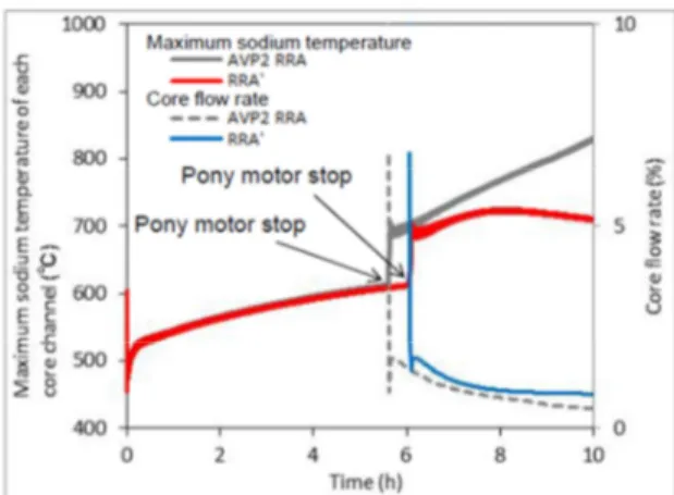
II.C.2. Impact on RRA operation without primary pumping
In order to evaluate impact of closable connection on RRA performance, following study case is considered:
• Loss of Offsite Power (LOOP)
• RRB operation neglected
• One RRA circuit operating
Additional trip of primary pumps pony motor when temperature reaches 600°C can be considered so that primary circuit is operating under natural circulation mode. Automated hydraulic connection is opened on pony motor trip signal. Results are shown on Fig 9 (case with DHX-Shutter is illustrated).
Fig 9: Thermal transient of NC onset under 1 RRA DHR conditions. RRA’ correspond to RRA plus Shutter-DHX
In reference case (grey curve) natural convection in primary circuit with RRA operation is not sufficient. In case additional flow path opening is triggered, satisfactory natural convection takes place (red curve).
II.C.3. Impact on Natural convection onset
This study shows the impact of additional hydraulic connection opening on Station Black Out (SBO) transient (design option with plug on inner vessel is illustrated). In simulated case, following conditions are considered:
• Pump trip at t=0
• Thermal flux through main cooling circuit is instantaneously canceled (no thermal inertia)
• No DHR system are considered for short term operation
Results are shown on Fig 10. Core outlet temperatures are presented: each curve of same color represent one hydraulic zone gathering several fuel assembly channels. Opening of additional hydraulic connection between hot and cold plenum lowers temperature peaks of roughly 150°C increasing core temperature margins.
Fig 10: SBO transient without secondary loop inertia: cases with and without additional hydraulic connection
between hot and cold plenum (plug on inner vessel option)
IV. CONCLUSIONS
Jointly developed by a French and Japanese design team, ASTRID decay heat removal systems are based on an adequate application of defense in depth principle with highlights by probabilistic assessment.
Diversification is the key point of ASTRID design with three types of systems in complement to the normal DHR system by ECS, which contribute to the robustness of the practical elimination demonstration. Option selection process of type of DHR systems and number of loops was
also driven and confirmed by static probabilistic assessment
Latest developments are presented in this paper with modification of DHR strategy during normal shutdown, increase of ex-vessel cooling capacities and enhancement of natural convection capacities with automated plug on inner-vessel.
Next step is to confirm Ex-vessel system role within practical elimination demonstration and consolidate role of automated plug opening within operating conditions.
ACKNOWLEDGMENTS
This paper includes the result of Technical development program of fast breeder reactor international cooperation, etc." entrusted to Japan Atomic Energy Agency (JAEA) by the Ministry of Economy, Trade and Industry (METI) in Japan.
REFERENCES
1. J. ROUAULT et al. “ASTRID, The SFR GENIV Technology Demonstrator Project: Where Are We, Where Do We Stand For?”, Proceedings of ICAPP 2015, Nice, FRANCE, May 03-06, 2015
2. J. ROUAULT et al. “JAPAN-FRANCE collaboration on the ASTRID program and sodium fast reactor” Proceedings of ICAPP 2015, Nice, FRANCE, May 03-06, 2015
3. F. CURNIER et al. “Use of simplified PSA studies to support the ASTRID design process”. Proceedings of ICAPP 2014, Charlotte, USA, April 6-9, 2014. 4. F. CURNIER et al. “Symbiosis of static and dynamic
probabilistic approaches to support the design process and evaluate the safety of a SFR” Proceedings of PSA 2015, Sun Valley, USA, 26-30 April, 2015