HAL Id: in2p3-00022687
http://hal.in2p3.fr/in2p3-00022687
Submitted on 5 May 2008HAL is a multi-disciplinary open access
archive for the deposit and dissemination of sci-entific research documents, whether they are pub-lished or not. The documents may come from teaching and research institutions in France or abroad, or from public or private research centers.
L’archive ouverte pluridisciplinaire HAL, est destinée au dépôt et à la diffusion de documents scientifiques de niveau recherche, publiés ou non, émanant des établissements d’enseignement et de recherche français ou étrangers, des laboratoires publics ou privés.
Simulations and measurements of the TTF phase-1
injector gun
T. Garvey, M. Omeich, M. Jablonka, J.M. Joly, H. Long
To cite this version:
T. Garvey, M. Omeich, M. Jablonka, J.M. Joly, H. Long. Simulations and measurements of the TTF phase-1 injector gun. 16th IEEE Particle Accelerator Conference (PAC 95) and International Conference on High-energy Accelerators (IUPAP), May 1995, Dallas, United States. pp.935-937, �10.1109/PAC.1995.505087�. �in2p3-00022687�
Simulations and Measurements of the TTF phase-1 Injector Gun
T. Garvey and M. Omeich
Laboratoire de l'Accélérateur Linéaire, IN2P3 - CNRS, Orsay, France.
M. Jablonka, J.M. Joly and H. Long
CEA, DSM/DAPNIA , Saclay, France.
Abstract
The TTF phase-1 injector will use a conventional thermionic triode gun as its electron source. The temporal structure of the injector will be obtained by the application of fast (< 1 ns) pulses to the gun cathode. As it is necessary to operate the injector at a fixed average macropulse current of 8 mA, while having the ability to vary the repetition frequency of the micropulses, the gun has to function at peak currents varying from 100 mA to 400 mA. We report on both measurements and simulations (using EGUN) of the current-voltage characteristics of the TTF gun. In addition we report on measurements of the emittance of the gun over a limited range of current and voltage. The emittance is seen to be dependent upon the operating perveance and is smallest for perveances closest to the space-charge limited value.
1. INTRODUCTION
The TTF phase-1 injector must provide the TTF linac with an average macropulse current of 8 mA. In addition it is forseen that this current should be provided using a time strucure (micropulse frequency) that can be varied. The highest frequency at which the injector can operate is 216.7 MHz, corresponding to the frequency of the sub-harmonic buncher (SHB) used on the injector [1]. However it desirable that the injector provide 8 mA average current at sub-multiples of the above frequency, notably 72.2 MHz. In order to achieve variable frequency operation of the injector we propose to modulate the gun current by the aplication of fast pulses to the cathode delivered via a wide-band amplifier. An average current of 8 mA for pulses at 216.7 MHz / 72.2 MHz implies a bunch population of 2.3x10⁸ e's / 6.9x10⁸ e's. Test measurements on the wide-band amplifier indicate that the gun output pulses will be quasi-triangular in form. As the base width of the pulses should be of the order of 0.64 ns, in order to ensure sufficient compression in the SHB, the figures above imply the need for peak gun currents of 115 mA / 345 mA.
In addition to the above beam current requirements the electron source for the TTF injector must deliver a beam of 250 keV energy. Although a suitable gun was commercially available we have preferred the solution, inspired from the S-DALINAC at the TH-Darmstadt[2,3] of using a triode gun providing 30 kV with the additional energy of the beam being furnished by an electrostatic accelerating column capable of sustaining 300 kV in air.
2. DESCRIPTION OF THE GUN
The triode gun is a modification of the gun, built by Hermosa Electronics, for use on the ALS linac at Saclay[4].
It has a classical "Pierce-like" geometry and employs an Eimac Y-845 cathode (emitting surface area = 0.5 cm2, cathode-grid spacing = 140 µm). In its original form the gun had a anode-cathode (A-K) gap distance of 97 mm and provided a nominal current of 100 mA at 40 kV. In order to have some margin for safety we should like to be able to operate the gun at 400 mA with 30 kV A-K voltage, consequently the gun has to be modified to increase its perveance, K (= I/V3/2) to 0.077
µPervs. A schematic of the modified gun is shown in fig. 1.
Figure 1. Schematic of TTF Gun. The distance from the cathode plane to the anode nose is 37.5 mm
3. GUN CHARACTERISTICS
The space-charge limited (SCL) current for a planar diode is given by the Child-Langmuir law,
I = 4ε0 9 2e me V 1.5A d2 or, I = kV1.5A d2
where A is the cathode area, d is the K distance, V is the A-K voltage, k = 2.33x10⁻⁶ A/V3/2 and the other symbols have their usual meaning. Approximating our gun geometry as a planar diode one would expect therefore that the we should reduce the A-K gap to 39 mm. Following quick exploratory runs with the E-GUN code[5] we have settled on a gap of 37.5 mm. We have reduced the A-K spacing by welding the focus electrode onto a long cylindrical stalk which is, in turn, welded to the original cathode flange (fig. 1).
935
© 1996 IEEE. Personal use of this material is permitted. However, permission to reprint/republish this material for advertising or promotional purposes or for creating new collective works for resale or redistribution to servers
3.1 EGUN Simulations
For the geometry corresponding to figure 1, EGUN runs predict that the SCL current will be 402 mA at 30 kV operating voltage. As well as reducing the A-K gap distance we have also performed simulations and measurements for the case were the length of the "nose" of the focus electrode is halved, from 14 mm to 7 mm. This modification was considered due to concern about electrical breakdown between the tip of the nose and the anode for the reduced gap distance. EGUN runs for this case show an additional increase of 25% in the perveance, i.e. K = 0.1 µPervs. However the outputs also show some increase in the divergence of the extracted beam, an effect which turned out to be much greater for the measured case (see below). For this reason, and following high voltage tests which showed that breakdown did not occur with the original focus electrode for A-K voltages up to 60 kV, we intend to work with the original focus electrode dimensions.
Examination of the EGUN output file shows that the current density at the the outer radius is only 5% higher than that on axis. However the phase-space at the edge of the beam suffers from a certain degree of aberration which is less severe for higher currents. A re-design of the focus electrode might allow some reduction of the effects of aberration.
3.2 Perveance Measurements
The measured characteristics of the gun are shown in figure 2 for various A-K voltages. One can see that the measured SCL current is 406 mA, in excellent agreement with the EGUN prediction of 402 mA (note that the planar diode approximation predicts 430 mA). Measurements for the reduced focus electrode nose length resulted in exactly the same 25% increase in perveance seen in the simulations.
Figure 2. Measured characteristics of the modified gun for varying A-K voltages.
4. THE GUN EMITTANCE
To be consistent with the definition used in EGUN we take the normalised emitance, εn = 4γβεrms, where
εrms = (<x2><x'2> - <xx'>2)1/2 ,
x and x' are the positions and slopes of the particles with respect to the beam axis and γ and β are the usual relativistic factors. The brackets imply the weighted averages of the quantities within them. The emittance specification for the injector is set by the requirement to maintain a small rms spot size (2 mm rms radius) in the linac for non-accelerated beams. This results in the need for a normalised emittance of the order of 20 mm-mrad. Higher charge electron injectors normally have emittances which are dominated by the beam dynamics in pre-bunching and bunching cavities. However, for our low charge case (37 pC/microbunch), PARMELA simulations indicate that emittance growth from the source (250 keV) to the end of the injector (10 MeV) is less than a factor of 2, hence the beam emittance is dominated by the value provided by the gun.
The intrinsic emittance of a non-relativistic thermionic gun is given by the expression,
εn = 2R kT
mec2
where R is the cathode radius and T is the cathode temperature. For our case, with R = 4 mm and T = 0.1 eV we would expect an emittance of 3.7 mm-mrad. However this value is well known to be optimistic as field non-uniformities around the grid wires will increase the angular spread of the electrons as they pass through the grid[6] (this effect would be minimised for the case where the grid is biased at a potential difference, w.r.t. the cathode, which just corresponds to the same potential difference which would exist in the absence of the grid[7]). Increases in emittance by factors of four to seven have been reported for guns employing triode configurations over identical geometries using simply a diode[8].
4.1 Emittance Measurements
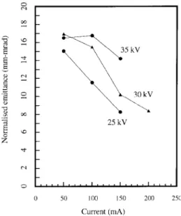
The emittance of the beam has been measured using a previously reported technique which takes into account the effects of the space-charge of the beam[9]. Since then, the process has been computerised with Labview. Beam profiles are digitally recorded, and 2σ radii are calculated. The range of current measurements was restricted to 200 mA due to the damage threshold of the current detector. Although the gun will be operated in a very short pulse mode (< 1 ns) the emittance measurements to date have been made using relatively long pulses of 3 µs as the fast pulser for the cathode was not available at the time of the measurement. The measured emittances, as a function of beam current and anode voltage, are shown in figure 4. One can see that, in general, for a given beam current the emittance increases with increasing voltage and that, for a given voltage, the emittance appears to decrease with increasing current. Of the ten data points one (50 mA, 35 kV) is not consistent with this remark however this point is sufficiently close to the point at 50 mA, 30 kV that the measurement error could easily account for this exception. These observations are consistent with the fact that the gun optic is optimised for one single value of perveance, i.e. the space-charge limited value. For this perveance the
external focus force provided by the gun geometry balances the self space-charge field of the beam. The further one reduces the beam current below the SCL value, for any given A-K voltage, the further this balance is reduced, resulting in inreased emittance[10]. Care should be exercised in using this arguement to explain the measured values as the situation is further complicated by the fact that different grid voltages are used to extract a particular current for a given A-K voltage. Therefore the contribution from the 'grid effect' mentioned above is not always the same.
As the EGUN runs are performed for the case of a diode, i.e. the simulations do not include the effect of the grid, one cannot expect to obtain good agreement between the calculated values and the measured ones[11]. The calculated emittance is found to be an increasing function of current but never exceeds the intrinsic value, consequently it is always inferior to the measured values. This same grid effect is responsible for the large measured beam divergences in comparison to the calculated values.
The smaller emittance values shown in figure 3 for smaller gun voltages might imply that it is best to operate the gun at the lowest voltage which will produce the required current. However, we wish to minimise growth of the transverse beam size in the electrostatic column (approximately 90 cm long) and therefore it may be advantageous to have the beam exit the anode aperture at higher voltages. Now that tests of the 40 kV gun are complete we will determine the optimum operating conditions for the gun-column assembly during forthcoming tests at SEA (Saclay).
Figure 3. Measured emittance as a function of gun voltage and current.
5. ACKNOWLEDGEMENTS
We are indebted to Bernard Jaquemard and the staff of the SECAP group at LAL for mechanical engineering work on the gun and to J.C. Bourdon and B. Aune for many
discussions on the gun. One of us (T.G.) is grateful to Bernard Mouton for computer support.
REFERENCES
[1] M. Bernard et. al., "The TESLA Test Facility Linac Injector", The proceedings of the 4th European Particle Accelerator Conference (London) 1994.
[2] K. Alrutz-Ziemssen et. al., "Status of the Darmstadt Near Infra-Red Free Electron Laser", Proceedings of EPAC 90, Nice, France, 1990, pp 562-564.
[3] The tube is available from High Voltage Engineering Europa, (Holland).
[4] B. Aune et. al., "Improvement of the Electron Injection for the ALS Electron Linac", Proc. of the Linear Accelerator Conference, California, USA, SLAC report 303, 1986. [5] W.B. Herrmansfeldt, "EGUN - An Electron Optics and Gun
Design Program", SLAC report 331, 1988.
[6] R.H. Helm and R. Miller, "Particle Dynamics", in Linear Accelerators, edited by Septier and Lapostolle, p 124. [7] Ron Koontz, private communication.
[8] B. Strongin and A. Salop, "Emittance determination of electron guns by analysis of beam profile measurements", Proceedings of the 1990 Linac Conference (Alberquerque), pp 758-760, Los Alamos report LA-12004-C, 1990.
[9] B. Aune et. al., "A Device for Gun Emittance Measurement", IEEE Trans. Nucl. Sci., Vol NS-32, pp1896-1898, 1985. [10] R. Chaput, "Canon SLL de CLIO", Internal Report of the
LURE Laboratory, Orsay, Linac/CLIO/8087, 1987
[11] M. Castellano et. al. "Commisioning and performance of a low emittance, long pulse electron gun for the superconducting linac LISA", Nuclear Instruments and Methods, Vol A 332, pp 354-362, 1993.