Design of a MAC Protocol for Wavelength Sharing in a Passive
Optical Distribution Network
by
Richard Thommes
B.Sc., Mathematics and Engineering: Control and Communications
Queen's University at Kingston, Ontario, Canada, 2000
Submitted to the Department of Electrical Engineering and Computer
Science
in partial fulfillment of the requirements for the degree of
Master of Science in Electrical and Computer Science
at the
MASSACHUSETTS INSTITUTE OF TECHNOLOGY
June 2002
@ 2002 Massachusetts Institute of Technology
All Rights Reserved
Author....
Certified b
Accepted
.. yJ BARKER MASSACH USETT I NSTITIUTEOF TECHNOLOGY
JUL 3 1200 2
LIBRARIES
... ...
Department of Electrical and Computer Engineering
May 16, 2002
Ni Professor Vincent W.S. Chan,
Director, EECS Laboratory for Information and Decision Systems
Thesis Supervisor
)y ..
... ...
Arthur C. Smith
Chairman, Department Committee on Graduate Theses
Design of a MAC Protocol for Wavelength Sharing in a Passive Optical Distribution Network
by
Richard Thommes
Submitted to the Department of Electrical Engineering and Computer Science on May 10, 2002
in partial fulfillment of the requirements for the degree of Master of Science in Electrical and Computer Science
Abstract:
The model under consideration in this thesis is a passive optical distribution network shared by a number of users generating IP packets that are destined for an edge router port at an access node. Each user generates data in a bursty fashion, meaning it only has packets to send a small fraction of the time. Therefore, in order to maintain efficient router port usage and to keep the cost low, a large number of users must share each port.
All the users connected to the port share a single wavelength (or a group of wavelengths).
This thesis develops a MAC protocol that allows the access router port and this wavelength to be efficiently shared between the users. A major impetus of the thesis is to identify presently available hardware that may be used to physically implement the protocol at a reasonable cost
An assessment is made of the theoretical delay and throughput characteristics of various classes of multi-access schemes. A reservation scheme is chosen as the best candidate.
A high level specification of a reservation-based MAC protocol is presented. This
specification defines all the control data which must be exchanged between the users and the access router in order for the protocol to operate, and addresses the need for
synchronization between all users and the router/scheduler. Next, the hardware
implementation of this protocol is addressed. An architecture making use of existing Gigabit Ethernet technology is suggested. Finally, the performance difference between a contention-based and contention-free version of the reservation MAC protocol is
Acknowledgements
Personal:
I would like to thank first and foremost my family: my parents, Fred and Rita, and my
brother Ed.
Further, I wish to acknowledge my fellow students at MIT:
Jason Bau, Serena Chan, Patrick Choi, Todd Coleman, Lillian Dai, Roop Ganguly, Chi (Kyle) Guan, Ramesh Johari, Desmond Lun, Tengo Saengudomlert, Etty Shin, Guy Weichenberg, Yonggang Wen
Academic:
Thanks to my thesis advisor, Dr. Vincent Chan.
This thesis was supported by the MIT Lincoln Laboratory under the Architectural Study for Next Generation Internet Award # BX-7276.
Contents
Introduction
...
6
1.1 O bjective
...
6
1.2 M odel
... 6
1. Analysis of M ulti-Access Schemes
...
9
1.1 Static TD M
...
9
1.1.1 O verv iew ... 9 1. 1.2 Throughput ... 9 1.1.3 D e lay : ... 101.2. Slotted A loha
...
10
1.2.1 Overview ... 10 1.2.2 Throughput ... 11 1.3 Slotted C S M A/C D ... 12 1.3.1 Overview ... 12 1.3.2 Throughput ... 13 1.4 O ptical C D M A ... 15 1.4.1 Overview ... 15 1.4.2 Throughput ... 16 1.4 .3 D elay ... 17 1.5 Reservation ... 17 1.5.1 Overview ... 17 1.5.2 Throughput ... 18 1.5 .3 D elay ... 181.5.4 Contention Reservation Optimization ... 22
1.6 Token-Passing ... 28
1.6.1 Overview ... 28
1.6.2 Throughput ... 28
1.6 .3 D elay ... 2 8 1.7 Preliminary Performance Evaluation ... 31
1.7.1 Slotted Aloha ... 32
1.7.2 Slotted CSM A/CD ... 32
1.7.3. TDM & O-CDM A: ... 33
1.7.4. Reservation and Token-Passing ... 33
2. Reservation Protocol Specification ... 37
2.1 O verview ... 37
2.2 Access Node Packets ... 37
2.2.3 Data packets ... 37
2.2.4 Control packets: ... 38
2.2.4.1 Types of Control Packets ... 38
2.3 User Packets ... 41
2.3.1 Data Packets ... 41
2.3.2 Control Packets ... 41
2.4. Registration... 42
2 .4 .1 U ser R em o val... 44
2.5 Timing ... 44
2.5.1 Synchronization ... 44
2.5.2 Synchronization Issues... 46
2.5.2.1 Precision of measured quantities ... 47
2 .5 .2 .2 C lock D rift... 47
2.5.3 Maximum discrepancy between AN and any user ... 48
2.5.4 Maximum discrepancy between any two users ... 48
2.5.5 Compensating for Propagation Delay ... 49
2.5.6 Collisions between Upstream Packets... 51
2.6 Reservation Schemes... 51 2 .6.1 Static T D M ... 52 2.6.1.1 A N O peration ... 5 4 2.6.1.2 U ser O peration ... 56 2.6.2 C ontention R eservation ... 58 2 .6 .2 .1 O peration ... 58 2.7 Scheduling Algorithm ... 59 3.
H ardware...
3.1 Gigabit Ethernet...61 3 .1.1 H isto ry ... 6 1 3.1.2 F ram e Structure ... 6 1 3.1.3 G igabit E thernet L ayers ... 623.1.4 Available Gigabit Ethernet Hardware ... 64
3.2 Im plementing the Reservation Protocol...65
3.2.1 Mapping Packets to GE Frames ... 65
3.2.2 U ser H ardw are ... 66
3.2.3 A ccess N ode H ardw are ... 70
3.2.3.1 Access Node Scheduler Hardware: A Closer Examination... 72
4. Perform ance Evaluation ... 77
4.1 TDM Reservation ... 77 4.2 Aloha-Contention... 80 4.3 Effect of Bounds... .83 5.1 Lim itations...84 5.2 Alternatives ... 85 5.3 Im provements... 86
5.3.1 Shortening the Reservation Interval... 86
5.3.2 Retaining Reservation Requests Exceeding the Bound... 87
Conclusion
...88
Appendix: Sim ulation ode
... ...89
Introduction
The use of fiber optics is commonplace in modem communication networks. The majority of long-distance telephone calls and Internet packets traverse a fiber link for at least part of their path through the network. While fiber optic technology is also utilized in access networks, it is typically implemented in the form of a point-to-point link between an end-user and an access node. This type of architecture requires that each user have its own dedicated port on a network access router. The problem with this approach is that if the users generate traffic in a bursty manner the port utilization will be low and the expense high. Since each user only transmits a small fraction of the time, the port will mostly sit idle. Furthermore, if a large number of users are to access one router, it becomes prohibitively expensive to have a separate port for each one.
1.1 Objective
The objective of this thesis is to develop a high level architecture design for efficiently sharing a router port between multiple users connected to a passive optical network. Solving this problem involves dealing with both Physical Layer and Data Link Layer (DLL) issues. Specifically, in order to share the channel, a DLL Multi Access Control
(MAC) protocol must be developed. In order for users to transmit their data, a Physical
Layer solution must be designed.
1.2 Model
The physical model of the distribution network consists of a number of users connected to an Access Node (AN) via a common fiber. The term "user" will be used to denote any entity other than the AN connected to the passive distribution network. A typical user may be a high-end workstation or a router terminating a corporate LAN. The AN consists of an IP router and hardware handling the MAC protocol functionality. Depending on the protocol chosen, this hardware's role may include sending control packets to the users and receiving control packets from them. Upstream control packets will be processed by the MAC hardware and will not be forwarded to the router port.
Downstream control packets will be interleaved with downstream IP packets. The
functionality of the MAC hardware is transparent to the IP router. Figure 1 illustrates an overview of the model.
Access Node IP Router MAC Hardware I __________________ Upstream IP Packets: X, Downstream IP Packets: X2 Shared ' Fiber (Multiple levels) (Multiple users) User N User 1 User 2 User N-1
Figure 1.1: Model Overview
A subset of users sharing a single wavelength destined for the IP router port will be
considered. A major focus of the research is to develop a scheme that could be implemented at a reasonable cost using technology that is presently available. As a result, for cost reasons, a separate control channel will not be used.
Users generate all their data in the form of IP packets. Some simple assumptions will be made about the bursty nature in which user IP packets are generated. Each user is typically only active about 10% of the time. The term "active" refers to a user being in a
state where it may generate IP packets. Users are assumed to be active independent of one another. The total number of active users follows a binomial distribution. While a user is active, it is not continuously generating packets. Instead, new packets are created
in bursts. Packet bursts arrive only during a small proportion of the time a user is active, on the order of 1%.
Packets destined for users connected to the port arrive at the IP router from elsewhere. They are modeled as being generated by a random process at the IP router. Once generated, they must be sent downstream to the users.
There may be as many as 1000 users in this group. The fiber connecting the users and the
AN is of a general broadcast structure. The average distance between the AN and the
users is 5km, and the maximum distance between the AN and any user is 10km. The fiber allows all the users sharing the port to send packets upstream to the AN. The
specific structure of the fiber will not be considered.
Upstream and downstream communication may occur simultaneously. This will be modeled as follows: Upstream packets are sent on wavelength X1, and downstream packets are sent on X2. If upstream and downstream packets are sent over the same
physical fiber, these wavelengths must be distinct. If separate fibers are used, X, and X2
1. Analysis of Multi-Access Schemes
The following section introduces the classes of multi-access schemes being considered to
form the basis of a MAC protocol for sharing the upstream wavelength. General
measures of their performance are provided. These performance measures include throughput and delay. In some cases formulas are omitted because analytical results are not available. Packets are assumed to be of a fixed length, each requiring X seconds to transmit over the shared upstream channel. There are N total users sharing the channel, and the upstream channel rate is C bits/second.
In order to obtain closed-form expressions for delay, a simplified model for the generation of new IP packets will be used. Namely, each of the A active users will generate packets according to a Poisson process of rate X. This is admittedly a violation of the assumption that packets arrive in bursts, since the Poisson process models packets as arriving one at a time. Rather than having -10% of the total number of users sharing the access network generating packets in bursts at any given moment - as is more likely to be seen in a real network - the model used will have them generate packets "smoothly". This means that any specific delay values derived are only approximations to the behavior of a real network.
1.1 Static TDM
1.1.1 OverviewUsers are synchronized to a common time source, and time is divided into fixed-length slots of length X. Each of the N users statically assigned every M h slot during which time
it may send a packet. If a user does not have any data to send during a slot, that slot remains idle.
1.1.2 Throughput
Each user is assigned 1/N of the total available upstream capacity. A user not generating data during a given time period wastes its entire allocation of the channel. Due to the nature of static TDM, wasted slots cannot be reallocated to other users. A user may only generate data while it is active, following the definition of Section 1.2. Thus, throughput is upper-bounded by the proportion of active users. If there are A active users,
A
throughputTDm - (1. N
1.1.3 Delay:
When a new packet is generated by a user, it must wait for all the packets ahead of it to be sent. Each user may be modeled as an M/D/1 queue. The average delay of this type of queue is given by the Pollaczek-Khinchin formula. It has the following general form [3]:
WMID/i =1yfl (1.2) 2 (1 - r8)
Here y is the Poisson rate at which packets arrive, / is the time required to transmit one packet, and WMD,,1 is the average queuing delay.
In the model under consideration, a user may only send once every N slots, meaning
/3=XN. Each user generates new packets at a rate of y =X.
In addition to waiting for all the queued packets to be sent, a new packet must wait till the user is first allowed to transmit during its allocated slot. Since there are N total slots, the average waiting time till the next assigned slot is:
NX
Wnextsiot = (1.3)
2
The total average delay is the sum of the (1.2) and (1.3):
AN2X2 NX
TDM 2(1- ANX) 2
1.2. Slotted Aloha
1.2.1 Overview
Aloha refers to a family of contention-based strategies in which each user sends data packets without checking whether the common channel is free. This means that users may collide with one another when attempting to transmit. The variant of Aloha considered here is slotted. This means users are synchronized to a common time source, and time is divided into fixed-length slots. The slot length is chosen to match the time required to transmit one packet. The packets generated are initially buffered before transmission. Users may only send packets at the beginning of a slot. During each slot every user that has buffered packets sends one with a certain probability. This probability must be strictly less than one. If this was not the case, throughput would drop
to zero following a collision: Each user involved in the collision would attempt to retransmit its packet in every subsequent slot and the collisions would continue ad infinitum.
1.2.2 Throughput
If there are M users with buffered packets to send, and each transmits with probability q
during a slot, the probability that a given user successfully transmits a packet is given by:
q(1- q)m~' (1.5)
The derivation of this expression is readily apparent: In order to be successful, the given user must attempt to transmit (an event of probability q), and the other users with packets must remain idle (each of the M-1 users is independently idle with probability (1-q), so the event of them all being idle is the product of the individual probabilities).
The system throughput is limited by the probability of a successful transmission. A success occurs when one user transmits, and all the other users remain idle. Since there are M users with packets to send, there are M different ways for a successful transmission to occur. These events are mutually disjoint, so the total probability of a success is just the sum of the individual probabilities of each event:
Psuccess = Mq(1-q)m-' (1.6)
The above is maximized for q = 1/M. If q can be adapted in "real time" to adjust for a
change in M, the algorithm is said to be stabilized. Stabilization is essential for the throughput to remain close to its ideal value. If M can be accurately measured, the maximum ideal throughput of stabilized, slotted Aloha - as function of the M - is given
by:
throughputideal, Slotted Aloha =
I
(1.7)M
1- 0.0-0.6 0.4 /e.- -- -- -- --- -0.2 0 1' ''20 30 40 50
NI&,mi di Usais Wh Palckes la Send Figure 1.1: Aloha Throughput
In reality, the exact value of M is typically not known exactly and is instead estimated. This lowers the throughput from the theoretical maximum illustrated in Fig 1.1.
1.3 Slotted CSMA/CD
1.3.1 Overview
Carrier Sense Multiple Access/Collision Detection has similarities to Aloha. It is also a contention based scheme in which collisions between users may occur. However, one difference with CSMA/CD is that users monitor the channel to make sure it is not in use before attempting to transmit. Collisions can still occur due to propagation delays: If a user finds the channel free it may be that another user has just begun broadcasting but its packets have not yet arrived at the first user. The other defining property of CSMA/CD is that a user continues to monitor the channel after it has transmitted in order to detect collisions, and ceases transmission after one time slot if it finds that one has occurred. The length of a time slot is determined by the maximum possible delay between a user sending a packet and determining that it was involved in a collision. Thus, if a user sends
a packet at the beginning of a slot, and does not detect a collision by the end of the slot, it will know with certainty that its transmission was successful.
1.3.2 Throughput
The maximum time to detect a collision is the maximum propagation delay between any two users: this is the longest it can take a transmitting user to determine another user is also transmitting. This value will be denoted by Tc. After a successful transmission ends, a contention period starts. It is divided into contention slots of length Tc. Just as with Aloha, each user with data packets to send will do so at the beginning of a slot with probability q. If a contention slot remains idle or a collision occurs, it is wasted. The probability of a successful transmission (exactly one user transmitting a packet) is Psuccess, given by (1.6), for each slot. Thus, the distribution of the number of contention slots needed till the first success is geometric, with an expected value of:
I Psurcess
It follows that the expected number of wasted contention slots is:
1 -1 (1.8)
Psuccess
Once a successful transmission occurs, a time period of length X will be used to send a data packet. Thus, for every successfully transmitted packet of length X, the average amount of wasted time is Tc multiplied by (1.8). This means the maximum average throughput is given by:
X 1 T
ThroughputCSMAICD T 19)'
X+TC - = 1+ a I
-For simplicity, the assumption has been made that X is an integer multiple of Tc. This allows a new contention period to begin immediately after the end of a successful transmission - no time is wasted waiting for the next contention slot to start.
After (1.6) is substituted into (1.9), it is elementary to find that the optimal value of q is again 1/M. This results in the throughput converging quickly, in M, to:
1
1+ a(e -1) (1.10)
While the derivation above assumed Tc < X and hence a < 1, (1.9) still holds for cases where this is not true. A value of a > 1 corresponds to the situation where, after the packet is sent, the channel stays idle while the transmitter waits for a collision that it can do nothing about. It is readily apparent that CSMA/CD is an illogical choice in this case: Collision detection is not only useless, it actually increases the delay. A value of a =1 corresponds to slotted Aloha: The sender does not stop transmitting due to a collision,
and does not continue to monitor the channel after it is done.
The following plot illustrates the dependence of maximum throughput (the optimal value of q is used) on the value of a:
ICShA/CD ft~d ghmIp 0.0- 0.6- 0.4- 0-2-0* a=0.5 a=0.5 10 3 40 50
NIohbd 9l Uses Wih PWeIts In Send
Figure 1.2: Aloha Throughput
As expected, values of a > 1 give poorer throughput than slotted Aloha. 20
1.4 Optical CDMA
1.4.1 Overview
Code Division Multiple Access (CDMA) has been successfully deployed for several years in cellular communication. Optical-CDMA is being studied as an alternative technology for sharing an optical channel [17]. In this scheme, more than one user may use the channel at any time. Each is assigned a unique binary "spreading code". When a user sends data, it multiplies the data by this code. Specifically, a "1" bit is sent by user i as:
F
ci (t)= Lci - p(t -t"
n=I
Here F is the length of the spreading code, [cin,n=1..F c [0,1] makes up the unique
spreading code for user i, and p(t) is a light pulse of a duration equivalent to the time needed to send one bit over the channel. The "0" bit is sent as an all zero sequence of length F. The receiver checks for the presence of a particular user's transmission by correlating the received signal, which is composed of the sum of all the coded signals sent by active users, with the particular user's spreading code.
In order for correct detection to happen, the autocorrelation peak, K, common to all users' codes, must be greater than both the cross correlation constraint A,, and the autocorrelation constraint La. These are defined by:
F
K = cj -c, Vj
n=1
This is equivalent to the number of "1"s in a spreading code.
F
Ar LCjnOCk n_ 0!m F-1,j*k
n=I
This is the maximum correlation between any shifted versions of any two distinct users' spreading codes.
F
2a Cjn Cjn+, 1 m F -1
The above is the maximum correlation between two shifted versions of the same spreading code.
O-CDMA may be either synchronous or asynchronous. The above formulae hold for
asynchronous O-CDMA, where a user may transmit at any time. In synchronous
does not matter, since it is not possible to simultaneously receive two time-shifted
transmissions from the same user. Furthermore, the A, constraint is less strict for
synchronous O-CDMA:
F
Ie Cj, 'Ckc j k
n=1
One class of optical codes that have been extensively studied [29] and are well
understood are Orthogonal Optical Codes (OOC). For these types of code, Aa and , are
unity. OOC codes are suitable for asynchronous O-CDMA. It should be noted that the usage of the word "orthogonal" to describe these codes represents a bit of a misnomer, since the cross correlation of distinct codes is not zero. The number of supportable unique codes N is related to F and K as follows:
N [ F-1 ,K >2 (1.11)
K(K -1)_
For a fixed N, increasing K (and hence F) lowers the probability of false detection at the receiver due to the presence of other users' transmissions. Specific expressions for the probability of error as a function of K lie beyond the scope of this paper
In the synchronous case, codes exist which have N=F. In fact, the simplest case of such a code is bit-based TDM: For N users, each user is allocated every N bit-slot. This still
meets the definition of an O-CDMA: The user assigned the j bit-slot is equivalently
assigned the spreading code (0.. .010...0) where the only 1-bit is in the jth position. As
one might expect, no codes exist with F<N.
1.4.2 Throughput
When a user wishes to send 1 bit, it must encode it as an F-bit sequence. Since all N users may transmit simultaneously, every transmitted F-bit sequence can carry 1 bit of data for every user. Using F transmitted bits to carry at most N bits of data limits the maximum throughput to N/F. Thus, of the total channel rate of C, only a fraction N/F is available for transmitting data.
Each user is effectively assigned 1/N of this available channel rate. As with static TDM, a user not generating data during a given time period wastes its entire allocation of the channel. Thus, with A active users, the total throughput is upper-bounded by the product of (1.1) and the fraction N/F:
ThroughputO-CDMA (1.12)
1.4.3 Delay
The average delay for O-CDMA is closely related to that of TDM. The substitution /=FX is made for equation (1.2), since each user may transmit at an effective rate of 1/F of the channel capacity. For non-synchronous O-CDMA, a user may send at any time, it does not have to wait till its next assigned slot. Thus, equation (1.3) does not apply, and the
average delay is given by:
AF 2 X 2
W O-CDMA, Asynchronous 2(1 - AFX) (1. 13)
For synchronous O-CDMA, a user may begin transmission once every F bit-slots. This means a newly arrived packet must wait on average F/2 slots before the user may transmit. Each of these slots is long enough to send one bit: 1/C seconds. Thus, the
average total delay for synchronous O-CDMA is: -AF2
X 2 F
W O-CDMA,Synchronous 2(1-FX) (1.14)
1.5 Reservation
1.5.1 Overview
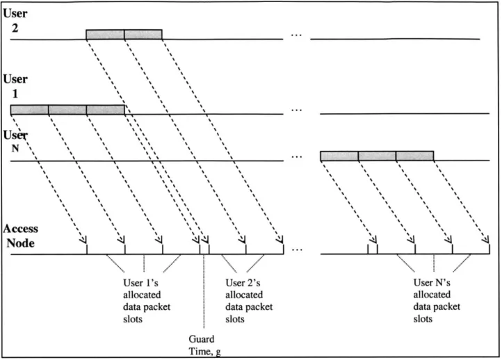
A reservation based multi-access strategy requires users to inform a central scheduler of
their intent to send accumulated data packets. The scheduler subsequently informs the users of when to send their packets, and how many may be sent. The scheme is divided into two alternating phases: the reservation phase, during which time users send their requests to the scheduler, and the data phase, when users transmit data packets as allocated by the scheduler.
There are two possible ways to implement the reservation phase, contention-free or contention-oriented. The contention-free approach divides the reservation interval using static TDM or O-CDMA. Since it was shown in Section 1.4.2 that O-CDMA requires at least as much time as TDM to send the same amount of data, only TDM reservation will henceforth be considered. Each of the N users is assigned a unique slot which it uses to request packet transmission times.
Contention-reservation reduces the length of the reservation interval, but requires users wishing to reserve to compete with one another when sending requests. The motivation is as follows: If only a small fraction of the N users typically have data packets waiting to be sent, most of the N reservation slots used in the contention-free scheme will remain
idle. The reservation phase represents overhead, and therefore should be made as short as possible.
Since users compete to send requests, collisions are possible. All users involved in a collision will be unsuccessful in their attempt to send a request to the scheduler. They must wait till the next reservation interval to try again. Thus, designing a contention-reservation scheme involves finding a balance between the length of the contention-reservation interval, and the probability that a user will be unsuccessful in reserving.
1.5.2 Throughput
The maximum achievable throughput is given by:
Maximum time spent sending packets per data phase
(Max. time spent sending packets per data phase)+(Avg. length of reservation phase) There is no inherent limit on how many packets may be sent during a data phase. Thus, assuming a fixed reservation phase length, the scheme can approach a throughput of close to 1.
In a typical implementation, the scheduler would place a limit on how many packets each user may send per data phase. This is to eliminate the possibility of a user sending a large number of packets continuously and choking off the other users for an extended period of time. With N total users sharing a channel, a bound of B packets/user/data phase, a reservation phase of length R and data packets that take a time X to transmit, the throughput is upper-bounded by:
ThrouhgputRe servation, Bounded < B (1.15)
NBX + R
If, for a given time period, it is known that only A of the N users are generating data
packets, N can be replaced by A for a tighter bound on the maximum throughput during that time.
1.5.3 Delay
The first case considered will be contention-free reservation, in which there is no bound on the number of packets each user may send per cycle. The derivation of this delay presented below is directly from [3]. It is repeated here to justify the use of a similar approach to later derive new expressions for the delays of bounded and contention-based reservation schemes.
The assumption is that newly generated packets are sent according to a first-come, first serve policy. This means that a newly generated packet must wait for three events to
complete between the times that it arrives and is transmitted. These include waiting for all the packets ahead of it to be transmitted, waiting through one reservation phase, and waiting through the residual time. The residual time is defined as the time to complete the transaction occurring at the instant the new packet is created: either the transmission of another packet or a reservation operation. Writing out an expression for the delay and taking expectations gives:
E{Wreservation, unbounded
}=
E{R} + E{}X + E{Q}Wreservation, unbounded = delay of a packet
Q
= residual timeR = duration of the next reservation interval
X= time to transmit one packet
K = total number of packets waiting in all users' queues
Next, Little's law is utilized. It states that if packets arrive at a rate r to a queue and wait an average time w before being sent, the average number in the queue is given by:
n = rw
Assuming a cumulative packet generation rate of a, one may apply Little's Law to find K:
K = aW reservation,unbounded
Using simplified notation, the average waiting time is now given by:
W reservation,unbounded = R + aX W reservation,unbounded +
Q
Solving forW reservation,unbounded
-R +Q
W reservation,unbounses = (1.16)
1- aX
Queuing theory provides the following expression for
Q:
- aX2 (1-aX)R2
Substituting this result into (1.16) provides:
aX2 R R2
W reservation,unbounded = +
-2(1 -aX) 1 -aX 2R
If the reservation interval is a fixed time R, the above simplifies to:
-aX 2 R 3-aX)
W reservation,unbounded = a +- (1.18)
2(1- aX) 2 I-aX
Now consider how this formula changes when a bound of B is placed on how many packets one user may transmit at any one time.
In this case, a packet may have to wait through more than one reservation interval until its reservation is made. In particular, if a user has 1 packets in its queue, a newly arrived packet must wait through
[
reservation intervals: a total delay ofR B
Here, R is considered fixed. If the distribution of r is f(q), then the expected number of additional reservation intervals a packet must wait is given by:
=0
[B
However, the distribution of 9 is generally not known, so one may proceed as follows. Let 0 A(Q) <1 be an unknown correction factor to compensate for the ceiling function
If
([)
= 7=0 B f(q) + A) = q=0Bf
07) -+ = n BB
Where A=E { AQ7) }: 0 A <1
Since all active users generate packets at a Poisson rate of A each, E{)7} can be obtained from Little's Law:
E{;} = XWreservaion,bounded
One may now enumerate the total delay seen by a newly arrived packet to a bounded reservation system. As in the unbounded case, it must wait for the residual time and for the packets ahead of it to be transmitted - these values remain unchanged. However, as discussed above, it must wait not through one reservation period of length R, but through
+ Aof them. Writing an expression for the delay gives:
B
A W reservation,bounded
Wreservation,bounded = + AIJ R + aXWreservation,bounded +Q
B
Rearranging,
AR+Q
W reservation,bounded
=-B
Substituting (1.17) for
Q,
one obtains:-
R
aX 2 AR +-(1-aX) W reservation,bounded = +RA2
RA21
1-aX-- (-aX-~ B )+BFinally, since A <1, the following inequality holds:
R
ax, 2 (3-aX )
W reservation,bounded <
-
-a
(1)2 1-aX - R
+(1-aX-Furthermore, Wreservation,bounded !Wreservaion,unbounded. This follows from the fact that a newly
arrived packet in a bounded reservation scheme must wait through at least one reservation interval, whereas in the unbounded case, a new packets only waits through
Next, the case of unbounded, contention-reservation will be considered. Let the length of a contention-reservation interval be given by R. Assume that the probability that a user attempting to register is successful in a given reservation phase is fixed at p. A new packet will, thus, have to wait for a randomly distributed number of reservation intervals, rather than just one as in the contention-free case. Since the probability of a success is fixed for all reservation intervals, this distribution is geometric with parameter p. Therefore, the average number of reservation intervals a packet has to wait through is 1/p
and the average total time waiting during reservation intervals is given by Rp. Everything else remains the same as in the unbounded, contention-free reservation. This means the contention-reservation delay is obtained by replacing R in (1.16) by RIp and following the same steps for the remainder of the derivation. The final result is:
W reservation,unbounded,contention = + R 1 +!- (1.20)
2(1-aX) p(1-aX) 2
One can proceed in a similar fashion for the bounded, contention based reservation scheme. A user has to wait through + AjJ successful reservations. Each of these
takes an average time of R/p. Everything else remains the same as the contention free bounded case, giving the following inequality for the delay:
X 2 RE(3-aX)
Wreservation ,bounded ,contenti.on R (3-A p A)121
R
iaxRA
(.12 1-aX- 1-aX
Bp Bp
1.5.4 Contention Reservation Optimization
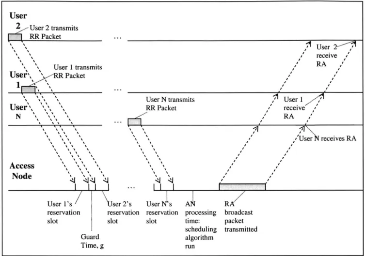
The contention scheme to be considered is slotted Aloha. In this approach, a certain number of slots (t) are available during each reservation phase. The number is not necessarily constant; in general it may change for each reservation phase. However, users are informed by the AN of how many slots are available before each reservation phase. Every user that has data packets to send will send a reservation request packet during the reservation phase. It will randomly pick one of the available slots.
Given the above assumptions, R, does not remain constant, since it is a function of (t). Specifically,
Re(t)= (t)Tr+T (1.22)
where Tr is the length of one reservation slot and Tf is a fixed value that accounts for other delays during the reservation phase. Tf is composed of a processing delay at the AN,
and a transmission and propagation delay associated with the AN sending a packet informing users when to send their data.
The value of p is also variable - it is a function of the number of users attempting to register during a given reservation interval, U(t), and the number of available slots. A user has its request successfully received if each of the other U(t)-J users chooses a different slot. Thus, the expression for p(t) is given by:
p(t) = ((t)1 = - I
()
1) (1.23)The fact that p(t) and R,(t) vary with time makes the analysis difficult. Thus, initially a simpler model of contention reservation - one where these values remain constant for all reservation intervals - will be examined. Keeping R,(t) at a constant value R, requires having the same number of reservation slots during each reservation phase. Thus, 4(t) will be fixed as
4.
In order for p(t) to be fixed as p, U(t) must be a constant U. Even though the assumption that the same number of users attempt to register each reservation phase is unrealistic, it will be made to allow the following calculations to proceed.Starting with (1.18), expressions for R, and p are substituted in:
aX2_
W reservation,unbounded,Aloha-contention = +(T + Tf )+ - (1.24)
2(1 - aX) r I (u-1)( X 2
In order to optimize the performance of the Aloha-reservation, contention-based protocol, the average delay must be minimized. Thus, given a value of aX - henceforth referred to as the load p - and U users attempting to register, the objective is to find an optimal number of slots . This is achieved by the standard approach of taking the derivative of the delay with respect to
4,
equating it to zero, and solving for4.
After simplification, the optimal value of4
is given by the solution to the following equation:U
2[ -U)+ Tf(1-U)]+ f j 2T(1- p) =0 (1.25)
An explicit solution for
4,
as a function of U, p, Tr, and Tf could not be obtained. However, (1.25) can be numerically solved for specific values of these variables.As mentioned before, the assumption that U remains constant is unrealistic. The model which will next be considered is one in which the number of active users, A, generating packets according to a Poisson process is fixed. will still remain fixed. A user will
only attempt to register during a reservation phase if it has any data packets waiting to be sent. Thus, U(t) will vary over time.
A user will have data packets waiting to be sent in the following cases:
1) The user generated at least one new packet since the previous reservation phase
2) The user generated no packets since the previous reservation phase, but generated one or more in the period between the beginning of the second last reservation and the beginning of the last reservation phase, and was unsuccessful in reserving during the last reservation phase.
3) The user generated no packets since two reservation phases ago, but generated
one or more in the period between the beginning of the third last reservation phase and the beginning of the second last reservation phase, and was unsuccessful in reserving during both of the last two reservation phases.
n) The user generated no packets since (n-1) reservation phases ago, but generated one or more in the period between the beginning of the nth last reservation phase and the beginning of the (n-1)th last reservation phase, and was unsuccessful in registering during the last (n-1) reservation phases.
The above pattern continues for an infinite number of cases. In order to perform further analysis, more variables must first be defined:
" Let T, be the time between the beginning of the current reservation phase and the
beginning of the previous one, T2 be the time between the beginnings of the
second last and last reservation phase, and in general let Ti be the time between the beginnings of the ith last and (i-1)th last reservation phase.
* Let pi be the probability of a successful reservation in the ith last reservation phase
Since each user generate packets generated according to a Poisson process of rate X, the probability f(n) that n packets are generated by a user during an interval of length Ti is given by:
f(n) =- 'AT
n!I
It follows that during an interval of length Ti, a user will generate no packets with probability e-A and generate at least one packet with the complimentary probability
p(l) = 1- e--"
p(2) e-"TI (1- e-T2 )(I - pl)
p(3) e-"'T e~"2 (1-e- )(1-p p -P2)
p(n) = e~" e-AT2 ...e-AT.-I (_ - p1 )(1 - P2)...(1-- Pn-1)
The probability P, that a user will attempt to register in the current reservation phase, is the infinite sum of these cases.
Ti and pi are random quantities with a joint distribution. Furthermore, the distributions of the two vectors (Ti, pi) and (Ti+, pi+,) exhibit dependence. This can be illustrated with1
the following example: A larger than average value of Ti makes it more likely users generated packets since the last reservation phase, meaning that the number of users attempting to register will tend to be higher than average -lowering the probability pi of a successful reservation for any given users. The high proportion of users unsuccessful in reserving results in fewer being allowed to send data packets during the subsequent data interval, thus tending to lower Ti+,. Furthermore, unsuccessful users will attempt to register again during the subsequent reservation phase and hence affect pi+].
The dependence described is not limited to consecutive intervals. For instance, it is apparent from the above example that the effect of the large Ti may extend to Ti+2 and Pi+2
and further.
Given the complex joint distribution of the random quantities, an expected value of the infinite sum describing the probability of a user register could not be found. To continue the analysis, several simplifying approximations will be made. A simulation will later be run to provide an indication of how closely the simplified approach approximates the true behavior of the contention-based reservation protocol.
First, all values of pi will be replaced by a fixed approximation p. Next, all values of Ti will be replaced by the expected amount of time between the beginning of consecutive reservation intervals, T. The value of T depends on the network load p and the length of the reservation phase, R,. The value of p must be the same as the average proportion of time dedicated to transmitting data packets. Packets are sent during the data phase, and the channel sits idle during the reservation phase. Thus, R, makes up an average proportion (1- p) of the length of average cycle (a cycle being one reservation phase and one data phase), and the data phase makes up a proportion p. Thus,
R, T =
1-p
(D
= (I-e~AT)[+ e-AT(I- p) +e2 AT( p) 2 + e-3AT(p) 3 +...] =(- e-A)T [e -A(T p)]" n=O e_'T )(1.26) 1-eA T (1 P)If there are A total users generating packets according to a Poisson process, an
approximation to the expected number of users, U, attempting to generate each reservation phase is given by:
AT
-I (- e- A(1--e 0)
U = = 1DA T(I-p) A = A -] (1.27)
1-e '-
(1-
p)Substituting in (1.22) into (1.25) provides:
A 1-e -AeT'+
U =~ - L _ ) _j- (1.28)
I- e P(1- p)
Since it takes X s to send one packet, the capacity of the channel, in packets/s, is 1/X. A
users generating at an average rate of A packets/second for a total load of p means the following relation holds:
=p - = P (1.29)
XA
Substituting (1.29) into (1.28) gives:
A
[1-e
-U = .-- -(1.30)
Finally, substituting in the following approximation for p: p 1 provides A l-e i( -U i= [- -l- - (1.31) pj{Tc+T J
ri-1
AX 1-p )Given values for Te, T, p, and A, an approximate relationship between
4
and U can be obtained using (1.31). For each value of4
substituted into (1.31), the corresponding value of U is found by numerically solving the equation. This procedure may be repeated for various values of4
to obtain a set of vectors (4, U). Finally, each vector can be substitutedback into (1.20) in order to find the choice of
4
that minimizes the average delay.It is important to emphasize again that the above relation is only an approximation, since random variables have been replaced by their expected values. Simulations should be carried out in order to get an indication of how accurate (1.31) is in providing an optimal choice of slots for a contention-based Aloha reservation scheme.
It is instructive to consider the limiting situation when p=1. This case corresponds to contention-free TDM reservation. Let RTDM be the length of the reservation interval. Making these two substitutions into (1.26) yields:
UTDM A l-e '-P (1.32)
Here UrD is the expected number of users that register during each reservation phase in a contention-free setting. Finally, substituting (1.29) into (1.32) provides:
_pRoryx
1.6 Token-Passing
1.6.1 OverviewToken passing is a contention-free, non synchronous scheme. Users are sequentially given a chance to send data packets through the use of a token, a special control packet that circulates between them. Upon receiving the token, a user transmits its queued data packets and, when finished, sends the token to the next users to continue the cycle. A user receiving the token when it has no data to send immediately forwards it.
1.6.2 Throughput
The throughput analysis is similar to that of the reservation case. The maximum achievable throughput is given by:
Maximum time spent sending data packets sent per cycle
(Max. time spent sending data packets per cycle)+(Time spent passing token per cycle) Where a cycle is defined as the period of time in which the token reaches each user exactly once.
There is no inherent limit on how many packets may be sent during one cycle. Thus, assuming a fixed time spent passing the token, the scheme can approach a throughput of close to 1.
If a limit B is placed on how many data packets a user may send per token possession and
the average amount of time to pass the token between any two users is L, the throughput is limited to:
BX
BX- (1.34)
BX+L
If, for a given time period, it is known that only A of the N have any data to send, the
token still has to pass between all the N users. In this case the throughput is limited to:
ABX ABX + NL
1.6.3 Delay
For the unbounded case, a newly generated packet by a given user has to wait for three events to transpire: all data packets queued by users that get the token before the given
user must be transmitted, the token must pass between all the users ahead of it, and the current residual time must come to an end. This is expressed as:
E{Wk,boudd }= E{Y} + E{K'}X + E{Q '}
Wtoken,bOunJed = queuing delay of a packet
Q'= residual time
Y= total duration of all token-passing operations the packet must wait through
X = time to transmit one packet
K '= number of packets queued by users that get the token before the given user must be transmitted
At first observation, E[K'} may seem difficult to calculate, since, unlike reservation, a token passing scheme does not transmit packets on a strictly first come, first serve basis. For instance, consider a case where there are 10 users, indexed by (1,..,10), with the token passing between them in the order of the index. If a new packet is generated at user 10 while the token is at user 5, the newly arrived packet will be transmitted before any of the queued packets at users 1 through 4 that arrived before it are transmitted. On the other hand, data packets that are generated by users 5 through 10 at times after the new packet under consideration is generated, and before the token leaves the respective user, will be transmitted before the packet under consideration. Fortunately, an important result from queuing theory [3] states that the average delay experienced by packets does not depend on the order in which they are transmitted (as long as the order is not influenced by the relative size of the packets). This result implies that the average number of packets transmitted before the newly arrived packet is the same as if packets were sent on a first come, first serve basis. Thus, from Little's law,
e = W token,unbounded
Where a= aggregate Poisson arrival rate of new data packets.
A newly arrived data packet is equally likely to arrive when the token is at any user.
Thus, since the token passes between all N users, on average the new packet must wait through N/2 token passing operations. Assuming the average time to transmit a token
is L,
- LN
Y
-2
Using simplified notation, the average waiting time is now given by:
-tLN
W okenunbounses =- + aX W tokenunbounded +V
Solving forfW , one gets
LN
--Wtoken,unbounded = 2
1-aX
Queuing theory [3] provides the following expression for
Q:
- aX 2 (1-aX)L
Q
=-+2 2
Substituting this result into the expression forW one obtains:
-aX 2 L( N +1I- aX )
Wtoken,unbounded = aX + ( -aX) (1.35)
2(1-aX) 2(1-aX)
Next, the bounded case will be considered. If a newly generated packet arrives to a queue with il packets, it must wait for
]
token-passing cycles. The first one of these will involve the token passing between N/2 users on average, and the remaining ones will have the token passing between all N users. Thus, in the bounded case, Y takes on a value of- = NL NL= -L[ 1)
2 B B 2
With analogy to the reservation case,
AW toen,bounded +A
B B
Therefore, for the bounded case,
Y=NjWtokn~bounded
B 2)
the expressions for K' and
Q'
remain unchanged. Solving for Wtokenbounded one obtains:-aX2 L(2A.N+1I- aX - N)
W2tokenbounded 2-aX- + 2
-aX- N
This provides the following inequality:
-- aX 2 L( N + I- aX )
W token,bounded < + L(N+2-aX ) (1.36)
21 1-aX- N 2 <i-aX-N
B B
Furthermore, Wtoken,bounded W token,unbounded . This follows from the fact that a newly
generated packet in a bounded passing scheme may have to wait for several token-cycles, whereas new packets in the unbounded case only wait till the token first arrives.
1.7 Preliminary Performance Evaluation
The viability of using the above multi-access schemes as the basis for a MAC protocol that shares the upstream wavelength between the users will now be examined. The objective here is to select a candidate, or candidates that warrant further investigation. Performance calculations are only estimates of true network performance, intended to eliminate weaker candidates.
Before proceeding, additional information must be presented. The physical layer
connectivity will be implemented using Gigabit Ethernet (GE) technology. An overview of GE will be given later. For now, the important characteristics of GE, in terms of impacting the performance of a MAC protocol, are summarized here:
* Maximum frame size: 1526 bytes (9026 if Jumbo Frames are used) * Minimum frame size: 72 bytes
* Channel Rate: 125 Mbytes/second
For simplification, the assumption will be made that all data frames sent by users are of
fixed length: the maximum 1526 bytes. There is some justification for this
simplification: When a higher layer process wishes to send some data, it will divide it into segments so that the data can be sent in the form of IP packets. Since the IP overhead bytes stay the same no matter the amount of data that an IP packet contains, higher layer processes tend to be optimized to send packets as large as possible. In fact, measurements of Internet traffic show [6] that the single most common IP packet size is 1500 bytes, which corresponds to a 1526 GE frame after encapsulation. Where appropriate, the effect of using fixed length 9026 byte jumbo frames will be considered.
Throughput is measured as the proportion of the 1 Gbit/s upstream channel that is available for sending data frames. Although 26 bytes of each data frame are overhead -or m-ore if the encapsulated IP packet headers are also considered - this factor will not be considered when calculating throughput since it is common to all multi-access schemes.
The number of users sharing the GE channel, N, may be as large as 1000. Since each user is active approximately 10% of the time, the expected number of active users is:
A =(0. 1)N
A further assumption is that users remain in their active or inactive states for long
durations of time, meaning A varies slowly and it may be accurately estimated during operation of the distribution network. The performance of the network at any point in time is a function of the current value of A.
1.7.1 Slotted Aloha
The above assumptions are not directly applicable to the Aloha throughput formula (1.7), since the number of users actively generating packets according to a Poisson process is not easily translated to the average number attempting to transmit during a given slot. However, some general conclusions can be drawn. The maximum throughput of Aloha drops below 0.5 when more than 2 users have data to send at any given time. Given that as on the order of 100 users may be generating traffic at any time, it seems reasonable to assume that typically more than 2 would be attempting to transmit at any time. Thus, one would expect the throughput to be less than 0.5, and indeed close to the limiting value of 1/e (-.36). A major impetus in designing the MAC protocol was to make efficient use of the router port. Clearly, a throughput this low does not meet the requirement.
1.7.2 Slotted CSMA/CD
One must find the value of a for the access network in order to evaluate the merit of a
CSMA/CD based protocol. Since users cannot receive upstream transmissions, they are
unable to do collision detection directly. The AN has to be involved, either detecting collisions and informing the users, or simply echoing back all transmitted frames. Tc would thus be twice the propagation delay from the user furthest to the AN: A transmitted frame must travel to the AN and come back. The furthest distance from any user to the AN is 10 km, and the propagation speed of light in fiber is approximately
2* 108 m/s. Therefore, 1.104m4 Tc = 2 1. M= 1.10~4 S 2-108 Mr/s Next, T - 1526bytes = 1.2.10-'s 125Mbytes I s
In this case, a= 10. If Jumbo frames are used, Tp will be increased by a factor of approximately 6, meaning a will still be greater than 1. Since CSMA/CD is only an improvement over Aloha for values of a smaller than 1, it warrants no further consideration.
1.7.3. TDM & O-CDMA:
Both of these candidates are quickly eliminated from contention because of the way they divide upstream capacity. They both assign 1/N of the total capacity (or less in the case of non-synchronous O-CDMA) to each user, whether it is generating data or not. Since the assumed model is that only approximately 10% of users are active at any time, the throughput is limited to about 0.1.
1.7.4. Reservation and Token-Passing
Before comparing the two remaining schemes, it is important to discuss how each would be implemented given the constraints of GE and the assumptions about the access network.
For the token-passing protocol, transmissions of the token between users must go through the AN since users cannot communicate directly. When a user has completed its transmissions, it informs the AN, which then informs the next user. The average distance from a user to the AN was given as 5 km, thus the token must travel an average of 10 km each time it moves between users. The actual token does not carry much information, only the address of the intended recipient (which is in every GE frame header anyway), so the shortest frame size of 72 bytes should be used. This frame must be transmitted twice per token-passing: by the user terminating transmission, and by the AN. Therefore, ignoring processing overhead at the AN, the average time to pass a token, L, is given as:
(5.0m
72 bytesL = 2(prop.delay + trans. delay) = 2 58MIS + b = 5.1152-10- s
(2-10m s 125Mbytes / s)
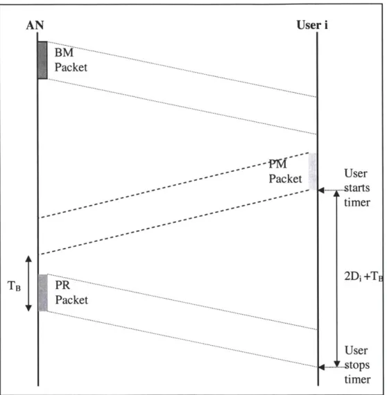
For TDM-based reservation, each of the users is assigned a slot to send a reservation frame in. Again, this frame will not carry much information, only the number of requested packets. Thus, a 72-byte frame will be used. The transmissions are scheduled, meaning that the frames can ideally be sent one after another if the users are perfectly synchronized to a common clock and compensate for their propagation delay to the AN. Unlike the token-passing protocol, the propagation delay will not be added to each transmission since the reservation frames are pipelined: While one is in flight, the next can already be sent; the propagation delay is only counted once for all the reservation frames.
After the AN receives the requests, it sends back a frame instructing all users when to transmit. Presumably this information could be contained within a maximum size frame of 1526 bytes.
An ideally synchronized TDM reservation interval is therefore composed of: the time to transmit all the user requests, the time for the last one to propagate to the AN, the time for the AN to transmit its frame, and the time for it to propagate to all the users. Processing delay is again ignored. For 1000 users, this represents a total length of time, R, of
R=l1000 72 bytes +2 1.104 M
125Mbytes / s) 2-10 m / s
(1526 bytes _4
+1I =6.8821- s
125Mbytes /Is)
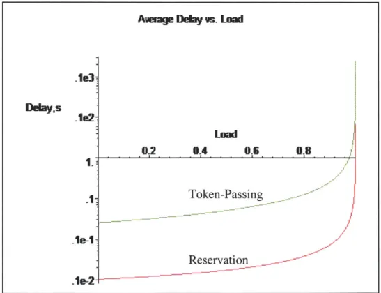
Given the values of R and L, it is now possible to compare the delay values of the two schemes. The remaining free parameter is a, the aggregate generation rate of new frames. It should be noted that a only appears in the delay formulae within the product aX. The significance of this product can be seen by considering the units of the two variables: X is the time it takes to transmit a frame, given in seconds/packet, and a is the rate at which new frames are generated, given in packets/seconds. Their product is a unit-less value between 0 and 1, representing the load placed on the network. This can be defined as the rate at which new frames are generated, as a fraction of the maximum rate at which frames can be transmitted across the channel. The network load will be the free parameter in the subsequent delay plots.
Average Delay vs. Lad
.10e3 Delay,s .1e2 0.2 0.4 0.6 0.8 .1 Token-Passing -.1e-1 Reservation .le-2