HAL Id: cea-01570529
https://hal-cea.archives-ouvertes.fr/cea-01570529
Submitted on 5 Jan 2018
HAL is a multi-disciplinary open access
archive for the deposit and dissemination of
sci-entific research documents, whether they are
pub-lished or not. The documents may come from
teaching and research institutions in France or
abroad, or from public or private research centers.
L’archive ouverte pluridisciplinaire HAL, est
destinée au dépôt et à la diffusion de documents
scientifiques de niveau recherche, publiés ou non,
émanant des établissements d’enseignement et de
recherche français ou étrangers, des laboratoires
publics ou privés.
Effect of laser shock peening on the high temperature
oxidation resistance of titanium
M Kanjer, M Lavisse, M Optasanu, Pascal Berger, M Gorny, M Peyre, M
Herbst, M Heintz, M Geoffroy, M Montesin, et al.
To cite this version:
M Kanjer, M Lavisse, M Optasanu, Pascal Berger, M Gorny, et al.. Effect of laser shock peening on
the high temperature oxidation resistance of titanium. Surface and Coatings Technology, Elsevier,
2017, 326, pp.146 - 155. �10.1016/j.surfcoat.2017.07.042�. �cea-01570529�
Effect of laser shock peening on the high temperature oxidation
resistance of titanium
A. Kanjer
a, L. Lavisse
a, V. Optasanu
a, P. Berger
b, C. Gorny
c, P. Peyre
c, F. Herbst
a, O. Heintz
a, N. Geoffroy
a,
T. Montesin
a, M.C. Marco de Lucas
a,⁎
a
Laboratoire Interdisciplinaire Carnot de Bourgogne (ICB), UMR 6303 CNRS-Université Bourgogne Franche-Comté, 9 Av. A. Savary, BP 47 870, F-21078 Dijon Cedex, France
b
NIMBE, CEA, CNRS, Université Paris-Saclay, CEA-Saclay, 91191 Gif sur Yvette, France
cPIMM Laboratory, UMR 8006 CNRS– Arts et Métiers ParisTech, 151 Bd de l'Hôpital, 75013 Paris, France
a b s t r a c t
The effect of laser shock peening on the high temperature oxidation resistance of commercial pure titanium at high temperature (700 °C) was studied in long-time (3000 h) exposure under dry air. A reduction of the gain mass by a factor 4 was found for laser-shock peened (LSP) samples compared to untreated titanium, which sup-ports the interest of laser-shock treatment for the improvement of high temperature resistance. Short-durations (10 h and 100 h) oxidation experiments, devoted to investigate the influence of the LSP treatment on the first stages of the oxidation process, were also carried out by TGA. Several techniques as scanning electron microsco-py, hardness and roughness measurements, X-ray diffraction and X-ray photoelectron spectrometry, micro-Raman spectroscopy, nuclear reaction analysis and electron backscattered diffraction were used to characterize the sample after laser treatment and oxidations. The formation of a continuous nitrogen-rich layer between the oxide layer and theα-case area in LSP samples appears to be the key factor to explain the reduction of oxygen diffusion, and thus the improvement of the oxidation resistance of laser shocked titanium. Moreover, the grain-texture of LSP samples after oxidation can also explain the improvement of the high temperature oxidation resis-tance after long times exposures.
Keywords: Titanium Laser shock peening High temperature oxidation Surface analysis
Nitrogen insertion
1. Introduction
Titanium alloys are widely used materials in the aerospacefield due to their high mechanical resistance combined with low density and ex-cellent resistance to corrosion[1]. Hence, titanium alloys are very attrac-tive for compressor section components in gas turbine engines working at temperatures between 300 and 600 °C[2]. Beyond that temperature, a deterioration of the passivation layer which covers titanium compo-nents and then an acceleration of the oxidation rate becomes possible. Moreover,flaws and cracks initiated at the surface can lead to fatigue and failure of these components.
Many surface treatments have been tested to develop suitable oxi-dation-resistant coatings for titanium alloys. Most of the treatments used for oxidation protection are chemical processes as pack cementa-tion coatings[6], ion implantation[7], and PVD ceramic coatings[8]. Another interesting way to improve the oxidation resistance, and also the fatigue performances of titanium alloys, can be a mechanical surface treatment. Indeed, large compressive stresses and surface hardening in-duced by mechanical treatments, such as shot-peening (SP) with WC
balls, has been reported to play a positive role in the oxidation resis-tance of zirconium for insresis-tance[9–10]. A beneficial effect of SP treat-ments on the high fatigue performance of several titanium alloys has also been reported[11]. However, shot-peening can induce surface contamination due to the wear of the balls during the treatment[12]. In this context, laser surface treatments have also been proposed as a competitive alternative technology to improve fatigue, corrosion and wear resistance of metals[11,13–17]. The high pressure shock wave generated in the interaction of a nanosecond pulsed laser beam (with power density in the GW/cm2range) with the metal surface can pro-duce deep compressive residual stresses with less cold work compared to SP[11]. Thus, the thermal relaxation of these residual stresses at high temperatures is lower after LSP treatments.
In the high temperature oxidation process of titanium, besides the rutile oxide layer formed on the surface, the inward diffusion of oxygen gives rise to the formation of a rich oxygen-content area, calledα-case
[3–4]. In the case of oxidation in air, the presence of atmospheric nitro-gen together with oxynitro-gen reduces the oxidation rate of titanium as shown by Coddet and Chaze[5]. Nitrogen is progressively incorporated in the rutile layer which grows from the beginning of the oxidation pro-cess. The higher diffusion coefficient of nitrogen in rutile compared to that of oxygen, leads to a progressive accumulation of nitrogen near
⁎ Corresponding author.
the metal-oxide interface, its dissolution in the metal being slower than that of oxygen[5]. This nitride layer slows down the oxygen diffusion and then brings a protection in terms of oxidation.
The aim of this work is to study the effect of laser shock peening on the high temperature oxidation resistance of commercially pure titani-um. A comparison between treated (LSP) and untreated samples (US) was led in terms of oxidation resistance at 700 °C under dry air. Long-time (3000 h) oxidation experiments under atmospheric air were done by furnace exposure, whereas Thermo-Gravimetric Analysis (TGA) under synthetic air was used for short-time (10 h and 100 h) oxidation experiments devoted to investigate the influence of LSP treat-ment on thefirst stages of the oxidation process. Surface and cross-sec-tion characterizacross-sec-tions by different techniques (X-Ray Diffraccross-sec-tion (XRD), Scanning Electron Microscopy (SEM) coupled with Energy Dispersive Spectroscopy (SEM/EDS), micro-Raman spectroscopy, Nuclear Reaction Analysis (NRA), Electron Backscattered Diffraction (EBSD), X-ray Photo-electron Spectrometry (XPS), micro-hardness and roughness measure-ments were mainly used to investigate the composition and the microstructure of untreated and LSP treated samples before and after the oxidation experiments. After the discussion of the results obtained by all these techniques, we will propose a model to explain the observed improvement of the oxidation resistance of titanium by LSP treatments. 2. Experimental details
2.1. Material
The material used in this study was a commercially pure titanium, 1 mm thick plate (grade I, certified purity 99.6%, Goodfellow). The ma-terial was manufactured by cold-rolling and annealing. The actual com-position of the metal was measured by Inductively Coupled Plasma Mass Spectrometry. The measured composition (in wt%) is the follow-ing: Ti bal., Fe 0.06, O 0.05, Co 0.03, Ni 0.023, Cr 0.018, C 0.011, Sn 0.01, Mo 0.01, Si 0.01, Al 0.005, Zr 0.005, Mn 0.005, Cu 0.002. The size of the samples used for laser treatments was 25x50x1 mm3. For TGA purposes, the samples are cut in small pieces (8x10x1 mm3). For
simplicity purposes, the untreated samples are named US (untreated sample) while the laser-shock peened samples are called LSP in the fol-lowing sections.
2.2. Laser shock peening (LSP) treatments
LSP treatments were done with a GAIA HP laser source operating at a 532 nm wavelength. All treatments presented in this study were done by using a focused beam with a typical 3 mm spot diameter. The laser shot frequency was 0.5 Hz and the pulse duration was 7 ns. The laser ir-radiance was 9.1 GW/cm2. The laser scanned the sample surface with a
velocity of 1.1 mm/s. This leads to an overlapping area of 30% between two successive impacts. LSP treatments were performed on both sample faces. The laser path is snake-shaped by describing successive displace-ments along parallel lines going and coming. The sample is covered dur-ing the laser shock by an aluminium adhesive coatdur-ingfilm in order to prevent the oxidation during the shot. For the laser irradiance values used here, each impact generates a plasma plume over the target which is confined near to the surface of the sample by both the confine-ment media. Here, water was used as confinement media to increase the shock amplitude. The use of a laser wavelength at 532 nm reduced laser beam absorption in the confinement media for increasing the LSP treatment effect[18]. When the plasma blows off, a back shock-wave is generated into the target. Then a large residual compressive stress with small amount of work hardening is obtained[13].
2.3. Mass gain measurements
The oxidation rates of US and LSP samples at 700 °C in dry air were studied in two different time exposure ranges.
- Long-time (3000 h) oxidation experiments were carried out within a SETNAG furnace at 700 °C under atmospheric air. The samples were extracted and weighed regularly.
- Short-time (10 h and 100 h) oxidation experiments were per-formed by isothermal exposure in thermo-gravimetric analyzer (TGA) using a SETARAM SETSYS EVOLUTION 1750. A heating rate of 10 °C/ min was used from ambient to 690 °C, then the heating rate was re-duced to 1 °C/min up to 700 °C.
2.4. Characterization techniques
The cross sections of the samples were resin-coated and mirror-polished. Cross-sections were observed by SEM coupled with an EDS microprobe analyzer (TESCAN VEGA 3) for determining the thickness of the oxide scale and the diffusion layer (namedα-case) size.
The surface roughness was measured using a surface roughness meter VEECO WYCO NT 9100. Micro-hardness measurements were made before and after LSP treatments using a ZWICK/ROEL indenter (Vickers's diamond pyramid) with a load of 50 gf. For quick alpha-case measurements purposes we used micro-hardness techniques in cross-section profile using 25 gf load, applied for 10 s.
X-ray photoelectron spectrometry (XPS) was used to investigate the possible surface-contamination of samples after LSP treatments. A PHI Versaprobe 5000 working with 41.6 W AlKα1radiation (1486.6 eV)
was used. The surface was cleaned before analysis by Ar ion beam bom-bardment for 1 min at 5 keV.
XRD and Raman spectroscopy were used to study the micro-phases formed in the oxidation layer. XRD patterns were obtained with a Bruker D8-A25 DISCOVER using Cu-Kα radiations at grazing incidence (θinc= 2°). Raman spectra were obtained with an InVia Renishaw
set-up working in backscattering configuration. The wavelength was 532 nm and the excitation power was relatively low (about 0.5 mW) to avoid heating the samples. Both sample surfaces and cross-sections were studied in this way.
The elemental composition of the samples was studied by ion beam analysis. In particular, the content and the distribution of light elements were analyzed by nuclear reaction analysis (NRA), which allows quanti-tative analysis of nitrogen and oxygen without influence of the chemical environment and a low influence of the roughness. This method has very good accuracy and is not sensible to the surface contamination dur-ing polishdur-ing since the measurements can be made under the sample's surface. The method used to analyze NRA spectra is extensively de-scribed in [19]. Here, a deuteron beam with a kinetic energy of 1900 keV was used to detect reactions involving nitrogen atoms, mainly the14N(d,α
1)12C nuclear reaction[20]. Cross-section maps of nitrogen
distribution in oxidized samples were obtained in this way.
Grain orientation was measured by Electron Backscattered Diffrac-tion (TSL EDAX OIM X4M EBSD system) coupled with afield-emission scanning microscope (FE-SEM, JEOL JSM-7600F). The working distance was 20 mm, the tension 20 keV, magnification ×70 and a step of 1 μm. 3. Results
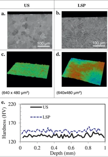
3.1. Characterization of as-prepared (non-oxidized) US and LSP samples Cross-section images, 3D–surface profilometry and micro-hardness profiles of US and LSP samples are shown inFig. 1.
SEM images (Fig. 1.a and 1.b) show grains morphology and size. In US samples the grains size is about 40μm. In LSP samples, the effect of the laser treatment is shown through the whole sample depth. The high density of twins induced by the LSP treatment prevents the obser-vation of the grains shape and size.
3D–surface profiles (Fig. 1.c and 1.d) show the different surface roughness of US and LSP samples. It was found that both Raand Rt
to 1.2 and 11.3μm, respectively. Thus, as expected, the laser-shock in-creases slightly the surface roughness.
Micro-hardness cross-section tests were performed in different points of the samples (Fig. 1.e). It was also found that LSP treatments in-creased the average samples hardness from about 135 HV for US sam-ples to about 155 HV for LSP samsam-ples. Thus, small work-hardening is noticed. No gradient in the hardness profiles is measured from the sur-face to the core of the material.
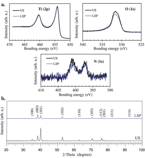
Measurements were carried out after Ar+ion bombardment of the
samples surface (Fig. 2.a). For US and LSP samples, no variation of the bonding energy is observed for titanium bands (Ti2p3/2at 454 eV and
Ti2p1/2at 460 eV[21]) and by consequence no oxidation or nitriding
is detected. This conclusion is supported by the stability of nitrogen and oxygen bands in US and LSP samples. XRD patterns showed only alpha titanium phase after LSP treatments (Fig. 2.b).
The comparison between XRD patterns before and after laser-shock treatment (Fig. 2.b) showed the decrease of the absolute intensity of all peaks after LSP treatment together with a small broadening of some peaks. Moreover, the relative intensity of the peaks (100), (101) and (110) was clearly reduced. On the contrary, the relative intensity of the peak (002) increased after LSP treatment. So, the LSP treatment can alter the crystallographic texture of the sample.
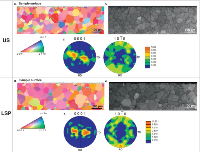
The EBSD analyses performed on US and LSP before oxidation were presented inFig. 3. The sample-border is cropped for texture determi-nation. The grain size observed inFig.3a for an US sample is in agree-ment with that shown inFig. 1a. For the LSP sample, some grains around 40μm in size are still present, but bigger grains about 100 μm in size can also be seen inFig. 3b.
Fig. 3a andFig. 3d show the maps grain orientation (HCP structure) obtained before and after treatment. The orientations plotted in these maps are reported to the sample surface normal direction (ND). For US, some twins can be observed on the image. These twins were prob-ably produced by the polishing process during the sample preparation. OnFig. 3b, few twins are observed. By comparison, for LSP, the grains map orientation (Fig. 3d) and IQ map (Fig. 3e) show a higher amount of twins. This twins are in majority compressive twins {11−22} 〈−1−123〉 (disorientation angle of 64°)[22]. The direct pole-figures (Fig. 3c andFig. 3f) showed a typical rolled texture for HCP structure (the c axis was slightly turned (about 30°) compared to the normal of the surface-sample (ND) toward TD)[23]. However, a slightly tilt around ND was observed and can to explained by the sample position during EBSD analysis.
3.2. Long-time (3000 h) oxidation experiments
Long oxidation tests were carried out to study the influence of LSP treatments on the oxidation behavior of titanium exposed to high tem-perature during several hours, which is of interest for industrial applica-tions. Oxidation test were performed here at 700 °C under dry air during 3000 h.
3.2.1. Oxidation kinetic behavior
Fig. 4shows the mass gain evolution for long-time (3000 h) oxida-tion experiments. The samples were placed in a furnace at 700 °C and were periodically extracted for mass measurement and then replaced in the furnace. The time between two successive measurements was progressively increased. After 3000 h the total mass gain in LSP samples was 6.7 mg/cm2, three times smaller than in US samples, which was
21.5 mg/cm2.
A general oxidation kinetics law was used tofit the experimental curves[24]:
Δm=S ¼ ktð Þ1=n ð1Þ
Here,Δm is the mass variation, S the sample surface, t the time, k the rate constant and n the degree index of the oxidation law, respectively. For the LSP sample, the experimental curve can befitted by Eq.(1)in the whole time range with a parameter n = 1.7. This value is close to 2, corresponding to a parabolic kinetic law, which is associated to a protec-tive barrier[24]. This shows that LSP treatment produces effective pro-tection against the oxidation.
For the US sample, three different regimes can be distinguished. Below 700 h, the curve variation can be assimilated to a pseudo-para-bolic curve which corresponds to a partially protective effect of this bar-rier. In the 700–1700 h range, the increase of mass gain rate reveals a breakaway phenomenon, which is attributed to the oxide layer crack-ing. For longer times, spallation of the oxide scale gives rise to the loss of the protective character of this layer.
3.2.2. Characterization of oxidized US and LSP samples exposed 3000 h at 700 °C
Fig. 5.a and 5.b show cross-section SEM views of the oxide layer ob-tained after 3000 h of exposure to dry synthetic air at 700 °C. The oxide layer thickness is about 130μm for US samples, whereas it is only about 40μm for LSP ones. Moreover, SEM images show the spallation of the oxide layer only for US samples. These observations agree with the study of the kinetics oxidation curves and they confirm the benefits of LSP treatment on the oxidation behavior of this material. Coupled to SEM observations, EDS analysis allowed to estimate the thickness of the ofα-case area. It was estimated to be about 180 and 100 μm for US and LSP samples, respectively. So, the LSP treatment also reduces sig-nificantly the thickness of the α-case area which can be associated witch a lower effective diffusion coefficient of oxygen in the metal.
Fig. 1. Cross-section and surface views of (a,c) US and (b,d) LSP samples. (a,b) SEM cross-section views in BSE mode. (c,d) 3D surface topographic view obtained with roughness-meter. (e) Micro-hardness profile.
After 3000 h exposure, SEM observations revealed also for all the ox-idized samples the formation of some precipitates which seem to be lo-calized at the grains boundaries. The results of EDS analysis revealed a high concentration of iron, around 100 times that in the mean composi-tion of this alloy (0.06 wt%), together with titanium. The formacomposi-tion of these Fe-rich precipitates can be explained as a consequence of the in-ward diffusion of oxygen in the oxidation process. Iron promotes the formation of theβ phase of titanium, whereas oxygen is an α-promot-ing element. So, the diffusion of oxygen in theα-case drives Fe atoms out of the grains in this area. According to the binary diagram Ti\\Fe proposed by Murray[25],α(Ti) and β(Ti) phases coexist for 0.06 wt% Fe at 700 °C but the system evolves toward a two-phases structure of α(Ti) and FeTi at room temperature. Diffusion of the Fe out of the grains in theα-case area increases the local Fe concentration at the grain boundaries and can give rise to the formation of Fe-rich precipitates on cooling. For LSP (Fig. 5.d), this precipitates were observed more than 100μm below the oxide-metal interface, whereas they were found deeper in US samples. This agrees with a lower diffusion of oxy-gen in LSP samples at 700 °C and the reduction of theα-case.
The phases formed in the oxide layer were studied by XRD and Raman spectroscopy. All results showed the formation of titanium diox-ide crystallized in the rutile phase for both untreated and LSP samples. No other titanium dioxide phase, like anatase, was observed.
Fig. 5.e and 5.f show Raman maps of the integrated area of the rutile bands (from 100 to 900 cm−1) for both samples (Fig. 5.c). For the US sample, the intensity of the Raman signal clearly decreases in the outer part of the oxide layer, whereas the intensity is almost constant in the whole thickness of the oxide layer for LSP samples. No other phases were observed and the signal background was almost constant. One can associate the decrease of the rutile Raman signal to a decrease
in the quantity for material due to the formation of a porous layer. For LSP samples, the Raman map reveals the formation of a homogeneous and compact rutile layer (Fig. 5.f).
3.3. Short time oxidation duration (10 and 100 h)
In order to understand the mechanism that can explain the better re-sistance of the laser-shock peened samples in long-time oxidation tests, we focused our study on thefirst stages of the oxidation. Thus, short-time oxidation tests were performed by TGA at 700 °C for 10 and 100 h under synthetic air.
3.3.1. Oxidation kinetic behavior
Fig. 6shows the results of quasi-continuous TGA measurements done on US and LSP samples exposed to dry air at 700 °C during 100 h oxidation experiments. As shown for short-time experiments, the mass gain after 100 h is smaller for LSP samples (1.75 mg/cm2
corre-sponding to 10% of the initial mass) than for US ones (2 mg/cm2).
For both samples, the experimental kinetic curves werefitted to Eq.
(1)in three different ranges:
I. Up to about 7 h, corresponding to the beginning of the oxidation process. Here, the value of n is closed to 1 corresponding to a lin-ear rate law for which the rate-limiting step is the metal/oxide interface reaction. For LSP the mass gain was higher by compar-ison of US during about 4 h infirst times of oxidation.
II. From about 7 up to 40 h, the value of n becomes 1.7 for US and 1.9 for LSP. The masse gain variation is close to a parabolic kinetic law which corresponds to a rate-limiting process given by the oxygen diffusion through a dense and protective barrier.
III. Above 40 h, the value of n slightly decreases to 1.6 for US and 1.7 for LSP. The diminution of the value of this value suggests that the oxide layer consists of an internal dense layer and an external cracked scale. The masse gain variation can be assimilated to a pseudo-parabolic kinetic law in this range.
This complex behavior is the result of several concomitant process-es: i) oxide layer growing, ii) inward diffusion of oxygen, iii) insertion of nitrogen and iv) eventual stratification of the oxide layer. The relative influence of each process determines the value of n in the different time ranges.
3.3.2. Characterization of oxidized US and LSP samples exposed 10 and 100 h at 700 °C
For 100 h of oxidation, the rutile (R) phase TiO2is the only phase
de-tected by XRD for US and LSP. For 10 h oxidation, nitrogen or oxygen so-lutions are detected for US and LSP by XRD (39° and 39.8° on XRD patterns). This peaks were strong for LSP in comparison of US which suggest major diffusion of light elements in this case.
Raman spectra of the oxide layer showed only peaks associated to the rutile phase of titanium in agreement with XRD results.Fig.7.c and 7.d show the maps corresponding to the intensity of rutile Raman signal. For both samples, the signal is almost constant through the whole layer thickness. Thus, no changes in the compactness of the oxide layer are observed for US samples for short times oxidation contrary to long oxi-dation time.
Fig. 7.a and 7.b display cross-section SEM views of US and LSP sam-ples after 100 h exposure to dry synthetic air at 700 °C. For 10 h oxida-tion time, the thickness of the oxide layer is higher for LSP (about 2.5 μm) by comparison of US (about 2 μm). For 100 h oxidation time, the thickness of the oxide layer is slightly higher for US sample (11μm) than for LSP sample (10μm), in agreement with the small difference in the measured mass gain (Fig. 4). A stratification of the oxide layer can also be observed inFig. 7.a for the US sample, whereas it seems less important for LSP sample (Fig. 7.b).
The thickness of theα-case area determined by EDS analysis is here about 10% smaller for LSP sample than for the US one. Micro-hardness tests forα-case determination depth (Fig. 7.g) confirmed the reduction ofα-case area for LSP (≈ 55 μm) by comparison of US (≈ 65 μm). This is in accord with SEM observations, as showed inFigs 7.a and 7.b. As seen in section 3.2.2 this difference increases up to almost 45% after 3000 h oxidation time. The diffusion of oxygen into the metal is strongly
Fig. 3. EBSD results obtained before oxidation for (a,b,c) US and (g,e,f) LSP samples. (a,d) Maps (850 × 250μm2
) of grain orientation (HCP structure). (b,e) Image quality maps (IQ) for strains deformation repartition. (c,f) Direct-polefigures.
Fig. 4. Mass gain as a function of the time for US and LSP samples in long-time (3000 h) oxidation experiments at 700 °C in dry air.
Fig. 5. SEM cross-section views obtained in BSE mode of (a) US and (b) LSP samples after oxidation at 700 °C during 3000 h. The oxide layer is labeled“Ox”. (d) Zoomed view of Fe-rich precipitates seen in (b). (c) Raman spectrum of the oxide layer showing the peaks assigned to the rutile phase of titanium dioxide. (e,f) Maps of the integrated intensity (dashed area in (c)) of rutile Raman bands in the oxide layer for US and LSP samples.
Fig. 6. Thermo-gravimetric analysis of US and LSP samples in short-time (100 h) oxidation experiments at 700 °C in dry air. Thefit of the experimental US curve to eq.(1)in three time ranges has also been drawn. The inset shows the same curves in logarithmic scales.
reduced by LSP treatment. The stratification can also be seen here but it seems to be less important for LSP treatment (Figs. 7.a and 7.b).
The EDS analysis also revealed the probable presence of nitrogen near to the interface between the oxide layer and theα-case area. How-ever EDS does not allow an accurate quantification of nitrogen content in titanium-based samples due to the overlap of the x-ray emission lines of both elements. Nuclear Reaction Analysis (NRA) is an interesting technique for the detection and accurate quantification of light ele-ments (O, N). It was used here to study cross-section of US and LSP sam-ples.Fig. 7.e and 7.f display NRA maps for Nitrogen. They correspond to the integrated intensity of the peak associated to14N(d,α
1)12C nuclear
reaction. The resin is composed of nitride aromatic heterocycles, by
consequence the detection of nitrogen inside is predictable. In agree-ment with EDS analysis, a nitrogen-rich area can be observed between the oxide layer andα-case area (this area has been delimited by white lines drawn on the maps to help the reader). For LSP samples, the nitro-gen-rich area forms a continuous layer, whereas discontinuous slabs are observed for the untreated sample. The composition determined by NRA points out the formation of a Ti(N,O) phase. In the oxide layer, NRA maps show also the presence of a small concentration of nitrogen for LSP samples, while nitrogen is almost absent for US samples.
The EBSD analyzes performed on US and LSP after oxidation during 10 h were presented inFig. 8. The maps are oriented in the oxide grow-ing direction (ND). For texture measurements, the sample-side
Fig. 7. Cross-section views of (a,c,e) US and (b,d,f) LSP samples after oxidation at 700 °C during 100 h. (a,b) SEM cross-section views obtained in BSE mode. The oxide layer is labeled“Ox”. A dashed grey line shows the depth of theα-case area. (c,d) Maps of the integrated intensity of rutile Raman bands in the oxide layer. (e,f) NRA mapping of nitrogen showing the integrated intensity of the peak assigned to the14N(d,α
1)12C nuclear reaction. White dashed lines bordering nitrogen-rich areas have also been drawn. (g) Micro-hardness measurements forα-case
including the resin and the oxide-layer is cropped. For US samples, a strong increase of the grain size, up to several hundreds ofμm, can be observed (Fig. 8.a). In comparison, LSP samples show much smaller grains, around 40–80 μm in size (Fig. 8.c). The high energy and high defaults density stocked after LSP treatment give rise to a refinement of the structure during recrystallization. The oxidation produced a change in the US texture (Fig. 8.b) compared to the situation before ox-idation (Fig. 3.c) and the rolling texture vanished. For LSP, there is a good correlation between texture before (Fig. 3.f) and after oxidation (Fig. 8.d).
4. Discussion
Fig. 9presents a model for non-oxidized and oxidized samples for short times oxidation (100h) and long times oxidation (3000 h) of oxidation, without treatment and LSP.Fig. 9.a and 9.b present the cross section model for untreated samples and laser-shock peening treatment respectively before oxidation. During LSP, the short time of impact is insufficient to create a grain refinement of the microstructure but the wave penetrates through the plate, and is reflected several times at the surfaces. Finally, the entire depth is affected (as presented in
Fig. 1.b). We can assume than in the case of LSP treatment presented here, compressive twinning is the main mechanism of material disorga-nization. Previous studies on LSP pointed out this effect on alloys[16, 26–27]. Nemmat-Nasser et al.[28]showed a major deformation by twinning on pure titanium during the application of high-strain rates at low temperature. For our samples, the direct pole-figures showed a typical rolled texture ofα titanium structure (Fig. 3.a andFig. 3.b)[23, 29]. Cellard et al.[30]showed a strong difference on residual stress values after laser shock peening treatment on 1 mm and 3 mm-thick Ti-17 plates. It should be noticed that probably the thickness of the ma-terial plays an important role in this type of treatment.
Fig. 8. EBSD results obtained after 10 h of oxidation at 700 °C in dry air for (a,b) US and (c,d) LSP samples. (a,c) Maps (2000 × 250μm2) of grain orientation (HCP structure). (b,d)
Direct-polefigures.
Fig. 9. Cross-section sketches of the US and LSP samples microstructure: (a,b) as-prepared samples (parallel lines indicate twins); (c,d) after oxidation during 100 h at 700 °C in dry air and (e,f) after 3000 h in the same conditions.
The texture presents higher intensity values for LSP (Fig. 3.f) and there is a correlation with (002) crystallographic plans detected with higher intensity on XRD patterns (Fig. 2.b).
As expected, no pollution was detected by XPS and XRD (Fig. 2.a and 2.b) and by consequence no chemical contamination of the samples could influence the mass gain intake during the oxidation tests.
Fig. 9.c and 9.d show schematic cross-section images of US and LSP after short oxidation experiments (100 h). The oxide surface layer is formed of rutile in both cases. A small concentration of nitrogen can be detected in LSP oxide layer only by NRA analyses. For 10 h oxidation times XRD results confirmed the presence of solid insertion of nitrogen in HCPα titanium structure after oxidation. The stratification of this layer is observed in US samples, as reported by several authors[31– 32]. A compact oxide layer is formed in LSP samples. The main effect of LSP treatment is the formation of a continuous nitrogen-rich layer between the surface oxide scale and theα-case area. It is worth remem-bering that the diffusion coefficient of nitrogen in the rutile phase is higher than that of nitrogen in theα titanium phase[5]. The excellent oxide scale adherence can be explained by the presence of an oxynitrides layer as previously reported by Torrent et al.[15]. For US samples, the insertion of nitrogen leads to the formation of discontinu-ous titanium oxynitride slabs. As a consequence, no oxygen barrier is generated in this case. This behavior was also observed by Coddet et al.[5]: the nitrogen layer reduces porosity and stress formation and by consequence the spallation of oxide layer. The depth of theα-case area is also higher for US than for LSP samples which can be explained by a highest value of the effective diffusion coefficient of O in Ti.
Gutman[33]has correlated the effect of mechanical treatments to the chemical reactivity of the material. LSP treatments can increase the entropy of the material and induce higher surface reaction rates. As a consequence, the formation of rutile in the veryfirst stages of the oxidation is more rapid for LSP in comparison with US. This observation is supported by theFig. 6: at the beginning of the oxidation, LSP shows a slightly higher oxidation kinetic rate than the US (during about 4 h). This observation is confirmed by 10 h oxidation tests: the oxide layer was smaller for US and the EBSDfigure for LSP (Fig. 8.c) showed a grain refinement which suggested a post-dynamic recrystallisation (ac-tivated by the default and a higher surface energy)[34]. The high grain boundaries density of the LSP samples could increase the oxygen and ni-trogen diffusion during thefirst stages of oxidation and by consequence support the formation of a rutile phase and the diffusion of nitrogen through it. For US the classical static-recrystallisation[35]occurs and then diminishes the diffusion of this lights element during thefirst times of oxidation.
The EBSD maps performed on oxidized samples revealed no twins for LSP after oxidation 10 h. The direct pole-figures show a conservation of texture for LSP but a change of texture for US. This can be explained by the energy stored in the laser-shocked material that facilitates the re-crystallization. With the conservation of grain textured (0001) in RD di-rection, the growing of rutile can be oriented during oxidation and the generation of better stoichiometric phase was possible for LSP. By con-sequence, the formation of continue nitrogen rich area in LSP could be explained by the better compacity and stability of the oxide layer in comparison with US.
Fig. 9.e and 9.f show a schematic view of the cross section model for untreated samples and laser-shock peening treatment respectively after long oxidation (3000 h). The LSP samples present an excellent behavior in term of high temperature oxidation resistance. Their kinetic curves are near to follow a parabolic law (Fig. 4). The n-value is 1.7 and near to n-value of section III as seenFig. 4. The oxide layer thickness is re-duced of about three times by comparison of US (Fig. 5.a and 5.b) and no spallation and porosities are observed (Fig. 5.c and 5.d). No nitrogen is detected with EDS microprobe between oxide layer andα-case area in LSP samples. This observation could be explained by the fact that tita-nium nitride is thermodynamically less stable than titatita-nium dioxide, and it decomposed during oxidation. In thefirst stages of the oxidation,
the grains orientation and nitrogen can play an important role in the formation of a compact rutile layer. During long oxidations, the more stoichiometric oxide layer formed on LSP samples (Fig. 5f) could play a role of barrier against oxygen diffusion. Finally, theα-case area is re-duced after LSP and this behavior is very important in terms of mechan-ical and structural properties. Indeed, theα-case is brittle, which is not suitable for aeronautical applications. Theα-case size reduction tends to show that LSP treatment modifies the effective oxygen diffusion coeffi-cient jointly with the blocking of oxygenflux income toward the oxide scale.
5. Conclusions
The effect of laser shock peening (LSP) treatments on the oxidation resistance of commercially-pure titanium at 700 °C in dry air has been studied for oxidation times going up to 3000 h. A significant improve-ment of the oxidation behavior of titanium in LSP treated samples was found compared to the untreated material. The main effects were: i) the reduction of mass gain for LSP by a factor 4 compared to US samples, ii) the formation of a compact and adherent oxide layer where spall-ation is almost absent, iii) a reduction of theα-case size which goes from about 300μm in US samples to about 150 μm in LSP samples. This indicates a decreased of the effective oxygen diffusion coefficient in LSP compared to US samples. The oxidation kinetic curves follow an almost parabolic law, which indicates the formation of a protective oxide layer.
It was also shown that LSP treatment produces a high density of twins through the whole sample thickness. Small work hardening is generated and no significant chemical pollution is observed. Moreover, a typical cold-rolling texture in good correlation with that observed be-fore the LSP treatment was found.
Thefirst stages of the oxidation process, up to 100 h, were studied in order to investigate the mechanisms leading to the higher oxidation re-sistance of LSP-treated titanium. After oxidation during 100 h, LSP sam-ples showed a recrystallization of the Ti-base probably promoted by the high density of defects generated by LSP, whereas untreated samples showed a grain growth process. Moreover, oxidized LSP samples con-served the initial rolling texture, while it disappeared in US samples. These effects of the LSP treatment can promote the growth of a compact and stoichiometric rutile layer which enhances the diffusion of nitrogen during oxidation. A continuous nitrogen-rich layer is formed between the oxide layer and theα-case area which is reduced in-depth. It ap-pears to be the key factor to explain the reduction of oxygen diffusion, and thus the improvement of the oxidation resistance of laser shocked titanium. So, the LSP treatment modifies the effective diffusion coeffi-cient of oxygen and reduces the oxygenflux through the oxide scale. This explains the higher oxidation resistance of LSP samples at 700 °C. References
[1] J.C. William, E.A. Starke, Progress in structural materials for aerospace systems, Acta Mater. 51 (2003) 5775–5799.
[2] Z. Huda, P. Edi, Materials selection in design of structures and engines of supersonic aircrafts: a review, Material & Design. 46 (2013) 552–560.
[3] J. Stringer, The oxidation of titanium in oxygen at high temperatures, Acta Mater. 8 (1960) 758–766.
[4] M. Dechamps, P. Lehr, Sur l'oxydation du titaneα en atmosphère d'oxygène : Rôle de la couche oxydée et mécanisme d'oxydation, Journal of Less Common Metals 56 (1977) 193–207.
[5] C. Coddet, A.M. Chaze, The role of nitrogen in the oxidation behaviour of titanium and some binary alloys, Journal of The Less Common Metals 124 (1986) 73–84.
[6] D.K. Das, S.P. Trivedi, Microstructure of diffusion aluminide coatings on Ti-base alloy IMI-834 and their cyclic oxidation behaviour at 650 °C, Material Science and Engi-neering 367 (2004) 225–233.
[7] A.K. Lal, S.K. Sinha, P.K. Bahrai, K.G.M. Nair, S. Kavalathy, D.C. Kothari, Effect of 60 keV nitrogen ion implantation on oxidation resistance of IMI 834 titanium alloy, Surf. Coat. Technol. 203 (2009) 2605–2607.
[8] A. Ebach-Stahl, C. Eilers, N. Laska, Cyclic oxidation behaviour of the titanium alloys Ti-6242 and Ti-17 with Ti–al–Cr–Y coatings at 600 and 700 °C in air, Surf. Coat. Technol. 223 (2013) 24–31.
[9] L. Raceanu, V. Optasanu, T. Montesin, G. Montay, M. François, Shot-peening of pre-oxidized plates of zirconium: influence of residual stress on oxidation, Oxid. Met. 79 (2013) 135–145.
[10] V. Optasanu, P. Jacquinot, T. Montesin, Influence of the residual stresses induced by shot-peening on the oxidation of Zr plates, Advanced Material Research 996 (2014) 912–917.
[11]E. Maawad, Y. Sano, L. Wagner, H.-G. Brokmeier, Ch. Genzel, Investigation of laser shock peening effects on residual stress state and fatigue performance of titanium alloys, Mater. Sci. Eng. A 536 (2012) 82–91.
[12] Y. Zengwu, F. Min, W. Xuegang, L. Xingeng, Effect of shot peening on the oxidation resistance of TP304H and HR3C steels in water vapor, Oxid. Met. 77 (2012) 17–26.
[13] H. Neila, P. Peyre, S. Hongbin, I. Popa, V. Ji, V. Vignal, Finite element analysis of laser shock peening of 2050-T8 aluminum alloy, Int. J. Fatigue 70 (2015) 480–489.
[14] P. Peyre, X. Sherpereel, L. Berthe, C. Carboni, R. Fabbro, G. Beranger, C. Lemaitre, Sur-face modification induced in 316L steel by laser peening and shot peening. Influence on pitting corrosion resistance, Mater. Sci. Eng. 280 (2000) 294–302.
[15] F. Torrent, L. Lavisse, P. Berger, G. Pillon, C. Lopes, F. Vaz, M.C. Marco de Lucas, Influ-ence of the composition of titanium oxynitride layers on the fretting behavior of functionalized titanium substrates: PVDfilms versus surface laser treatments, Surf. Coat. Technol. 255 (2014) 146–152.
[16] X.C. Zhang, Y.K. Zhang, J.Z. Lu, F.Z. Xuan, Z.D. Wang, S.T. Tu, Improvement of fatigue life of Ti–6Al–4V alloy by laser shock peening, Mater. Sci. Eng. 527 (2010) 3411–3415.
[17] Y. Hua, Y. Bai, Y. Ye, Q. Xue, H. Liu, R. Chen, K. Chen, Hot corrosion behavior of TC11 titanium alloy treated by laser shock processing, Mater. Sci. Eng. A 527 (2010) 3411–3415.
[18] P. Peyre, C. Carboni, P. Forget, G. Beranger, C. Lemaitre, D. Stuart, Influence of ther-mal and mechanical surface modifications induced by laser shock processing on the initiation of corrosion pits in 316L stainless steel, J. Mater. Sci. 42 (2007) 6866–6877.
[19] H. Khodja, E. Berthoumieux, L. Daudin, J.P. Gallien, The Pierre Süe laboratory nuclear microprobe as a multi-disciplinary analysis tool, Nucl. Instrum. Methods Phys.Res. B—Beam Interact.Mater. Atoms 181 (2001) 83–86.
[20] A. Gurbich, S. Molodtsov, Measurement of (d,p) and (d,α) differential cross-sections for14
N, Nucl. Instrum. Methods Phys.Res. B - Beam Interact. Mater. Atoms, 266 (2008) 1206–1208.
[21] J.F. Moulder, W.F. Stickle, P.E. Sobol, K.D. Bomben, Handbook of X-ray Photoelectron Spectroscopy, Physical Electronics, Inc, 1995.
[22] A. A. Salem, S. R. Kalidindi, R. D. Doherty, Strain hardening regimes and microstruc-ture evolution during large strain compression of high purity titanium, Scripta Materialia, (46) 2002 419–423.
[23] G.G.E. Siward, S. Celotto, D.J. Prior, J. Wheeler, R.C. Pond, In situ SEM-EBSD observa-tions of the hcp to bcp phase transformation in commercially pure titanium, Acta Mater. 52 (2004) 821–832.
[24] P. Kofstad, K. Hauffe, H. Kjöllesdal, Investigation on the oxidation mechanism of tita-nium, Acta Chem. Scand. 12 (1958) 239–266.
[25] J. L Murray, The Fe-Ti (Iron-Titanium) System, Bulletin of Alloy Phase Diagrams, 2 (1981) 320–334.
[26] W. Jia, Q. Hong, H. Zhao, L. Li, D. Han, Effect of laser shock peening on the mechanical properties of a near-α titanium alloy, Material Science and Engineering 606 (2014) 354–359.
[27] Z. Cao, H. Xu, S. Zou, Z. Che, Investigation of surface integrity on TC17 titanium alloy treated by square-spot laser shock peening, Chin. J. Aeronaut. 25 (2012) 650–656.
[28]S. Nemmat-Nasser, W.G. Guo, J.Y. Cheng, Mechanical properties and deformation mechanisms of a commercially pure titanium, Acta Mater. 47 (1999) 3705–3720.
[29] M.E. Nixon, O. Cazacu, R.A. Lebensohn, Anisotropic response of high-purity α-titani-um: experimental characterization and constitutive modeling, Int. J. Plast. 26 (2010) 516–532.
[30] C. Cellard, D. Retraint, M. François, E. Rouhaud, D. Le Saunier, Laser shock peening of Ti-17 titanium alloy: influence of process parameters, Mater. Sci. Eng. 532 (2012) 362–372.
[31] S. Kumar, T.S.N.S. Narayanan, S.G.S. Raman, S.K. Seshadri, Thermal oxidation of CP Ti - an electrochemical and structural characterization, Mater. Charact. 61 (2010) 589–597.
[32]J. Unnam, R.N. Shenoy, R.K. Clark, Oxidation of commercial purity titanium, Oxid. Met. 26 (1986) 231–252.
[33] E.M. Gutman, Mechanochemistry of Solid SurfaceWorld scientific 1994.
[34] T. Sakai, A. Belyakov, R. Kaibishev, H. Miura, J.J. Jonas, Dynamic and post-dynamic re-crystallization under hot, cold and severe plastic deformation conditions, Prog. Mater. Sci. 60 (2014) 130–207.
[35] C. Kerisit, Analysis of static recrystallization mechanisms of cold-worked tantalum for mean-field modeling, PhD Thesis (in French), Ecole Nationale Supérieure des Mines de Paris, 2012.