HAL Id: cea-02355796
https://hal-cea.archives-ouvertes.fr/cea-02355796
Submitted on 2 Dec 2019
HAL is a multi-disciplinary open access
archive for the deposit and dissemination of
sci-entific research documents, whether they are
pub-lished or not. The documents may come from
teaching and research institutions in France or
abroad, or from public or private research centers.
L’archive ouverte pluridisciplinaire HAL, est
destinée au dépôt et à la diffusion de documents
scientifiques de niveau recherche, publiés ou non,
émanant des établissements d’enseignement et de
recherche français ou étrangers, des laboratoires
publics ou privés.
Durability design of heated concrete
structuresMethodology and application to long-term
interim storage
H. Lagrave, G. Ranc, C. Galle, S. Durand
To cite this version:
H. Lagrave, G. Ranc, C. Galle, S. Durand. Durability design of heated concrete structuresMethodology
and application to long-term interim storage. Journal de Physique IV Proceedings, EDP Sciences,
2006, 136, pp.223-231. �10.1051/jp4:2006136023�. �cea-02355796�
The headers will be insert by the Publisher
Durability design of heated concrete structures
Methodology and application to long-term interim storage
H. Lagrave
1, G.Ranc
1, C. Gallé
2and S. Durand
21
CEA Valrho 30207 Bagnols sur Cèze France
2
CEA Saclay 91192 Gif sur Yvette France
Abstract. The operation of civil engineering structures subjected to thermal and mechanical loading has
led the CEA to examine temperature-dependent variations in the concrete properties and the processes affecting the durability of these structures.
A new approach has been undertaken to specify the thermal, hydric and mechanical history of these structures. This technical approach is based on three areas of research: material characterization, modelling to identify weaknesses in the structure and validation by experimental tests on heavily instrumented structures subjected to representative loads.
The procedure adopted for long-term interim storage facilities [1, 2] can also be applied to other domains.
1. INTRODUCTION TO THERMAL HYGRO MECHANICAL (THM) PROGRAM
The main goals are studying the evolution with temperature of microstructural properties of concrete, understanding damage processes in heated concrete and during heat cycles and studying effect of temperature gradients and pore pressures on concrete strength.
The mechanical properties of concrete are determined by its mechanical, hydric, thermal and chemical history (degradation, transformation of hydrates, formation of new species) and loading time.
The chemical transformations are accompanied by increasing porosity, loss of mechanical properties and increasing transfer properties with the temperature [6].
In the 80-200°C range which concerns us particularly, there is no clear threshold for the mechanical properties of concrete with a water-to-cement weight ratio below 0.5, with Portland cement.
Phenomenological models exist within the CEA to estimate the effect of drying on the mechanical behaviour and thermo-hydro-mechanical behaviour of the concrete.
These tools have been extensively validated by tests at centimetre scale but full-scale validation tests must still be carried out certain cases: this is the objective of the GALATEE program.
JOURNAL DE PHYSIQUE IV 2
2. MATERIAL PARAMETERS CHARACTERIZATION
Experimental characterization focused on concrete thermo- hydric-mechanicals residual properties after thermal loading between 60 and 250°C (and up to 450°C in some cases). In it considered that for some concepts, high level waste canisters will be placed in concrete structures. In a normal evolution scenario, cooling systems will keep the temperature of these structures around 60°C. But in case of their temporary failure, high temperatures could be reached – up to 250°C – [3]. In such conditions, thermally related degradations, like drying, cracking or spalling, could drastically reduce concrete mechanical, confinement, and durability performances. It is essential therefore to characterize and to study the evolution of thermo- hydric-mechanical (T-H-M) properties of materials which could be used under such severe temperature conditions.
All these results were part of a large data bank dedicated to concrete thermo- hydric-mechanical properties in severe thermal conditions.
Concrete behaviour at high temperature depends on thermo-mechanical processes related to temperature gradients generating thermal expansion gradients [4, 5] and on thermo-hydric processes
related to water – liquid and vapour – movements [6, 7]. The kinetics and amplitude of such processes
are controlled by micro– and macroscopic parameters. At material scale, those parameters are: thermal conductivity (), heat capacity, water and gas (kg) permeability, porosity (), mechanical –
compressive (fc) and tensile strength, elastic modulus (E) – and thermo-mechanical properties –
thermal expansion. Such properties were characterized for various high-strength concretes in order to constitute a data bank and to provide input data for the models. In addition to the potential impact of the intrinsic characteristics of the materials (water-cement ratio, cement and aggregates type), [8, 9]
other influencing factors, designed as external characteristics, were investigated: long duration and cyclic thermal loadings, heating rate, concrete water saturation degree [9, 10]...
The majority of the phenomenological studies were carried out with two high-strength concretes (HSC). A standard HSC (w/c 0,43) was prepared with a CEM I-OPC cement (350 kg/m3) and with
silico-calcareous aggregates. A second one was manufactured with the same cement but with hematite aggregates (already used for nuclear radiobiological applications). Hematite is characterized by high density (, 5.103 kg/m3), high thermal conductivity (11 W/m/°C) and high elastic modulus (209 GPa).
Thermal loadings focused mainly on a temperature range between 60 and 250°C; extreme loadings were also performed up to 450°C in order to estimate margins). HS concretes characteristics are resumed in Erreur ! Source du renvoi introuvable..
Table 1. Initial characteristics of HS concretes (at 20°C)
HSC type (kg m-3) (%) k
g (10-19 m2) (W m-1 K-1) fc (MPa) E (GPa)
Standard 23788 10.40.4 1.61.9 2.70.1 633.9 492
Heavy 406758 10.00.5 3.94.7 7.30.4 784.9 812
Example of properties evolutions with temperature of such concretes under severe thermal loadings are provided within the figures 1 and 2. Concerning the effect of thermal treatment on microstructure, it was observed that the different heating generated important capillary porosity. This porosity is represented by a large population of pore access located in the region between 0.02 and 0.2 µm. This phenomenon was not only detected for high temperatures (over 110°C) but also for lower temperatures such as 60°C (Figure 1a). The development of cracking that influenced significantly the permeability was mainly observed over 250°C – the reference limit for accidental scenario – (Figure 1b), above all for the standard HSC. Concerning thermal conductivity, a linear evolution was globally observed for both concretes.
a b
Figure 1. Effect of thermal treatments on MIP pore access distribution (a) and effective gas permeability (b) for
standard and heavy HSC [7, 9]
About the evolution of mechanical properties with the temperature, it was detected that up to 110°C, HSC were characterized by an increasing compressive strength (heavy concrete) or at least a stable one (standard concrete). Over 110°C a monotonous decrease of this parameter was observed (Figure 2a). At 250°C a relative decrease of 16% was estimated for the standard concrete while for the heavy concrete the compressive strength loss was limited to 4%. The evolution of the elastic modulus (residual parameter) with the temperature was assumed to be linear. Similarly to the other parameters, once again it was observed that due to the mechanical characteristics of hematite aggregates, the residual elastic modulus for the heavy concrete (from 85 GPa at 60°C to 69 GPa at 250°C) was higher than the standard concrete ones (from 44 GPa at 60°C to 26 GPa at 250°C) for which the relative property loss – between 60 and 250°C – was about 50 %.
a b
Figure 2. Evolution of compressive strength with temperature for standard and heavy HSC (a) and effect of
heating rate on elastic modulus for standard HSC (b) [8, 9]
Another specific study focused on the potential effect of the heating rate on the mechanical properties of a standard HSC. Numerical simulations showed that in case of the temporary failure of the cooling systems of the storage facility, high temperatures could be reached in the structures – up to 250°C. In that configuration, temperature rate increase should be around 0.1°C/min and not exceed 0.5°C/min. In the framework of this problem, impact of heating rates ranged from 0.1 to 10°C/min on concrete thermo- hydric-mechanical properties was estimated. The results showed that the lowest compressive strength loss was observed when using the lowest heating rate (0.1°C/min) and that this behaviour was consistent with previous studies performed on ordinary and HSC materials. On the contrary, an opposite trend was detected with the elastic modulus (Figure 2b) for which the lowest residual values were obtained with the 10°C/min rate. Nevertheless it was noticed that the impact of the heating rate was quite limited for both parameters (less than 10% relatively).
1,E-18 1,E-17 1,E-16 1,E-15 1,E-14 1,E-13 1,E-12 0 50 100 150 200 250 300 350 400 450 500 Temperature (°C) Effec tive p ermea bility (m 2) Ordinary HSC Hematite HSC 20 25 30 35 40 45 100 150 200 250 Temperature (°C) E la s ti c mo d u lu s ( G P a
JOURNAL DE PHYSIQUE IV 4
3. MODELLING OF CONCRETE BEHAVIOUR
Still in the framework of the same research program, several models have been developed to address different aspects of the behaviour of concrete at high temperature. The TH aspects are treated by a simplified TH model that rests on the assumption that the gaseous phase is only composed of vapour which permits to combine the two initial mass conservation equations of water in liquid and gaseous phase into only one. To deal with TM problems in concrete, a plasticity model has been developed. Finally, a coupled THM model based on the mechanics of partially saturated porous media [12] is being developed with the same assumption that the TH model and with a damage model to describe cracking.
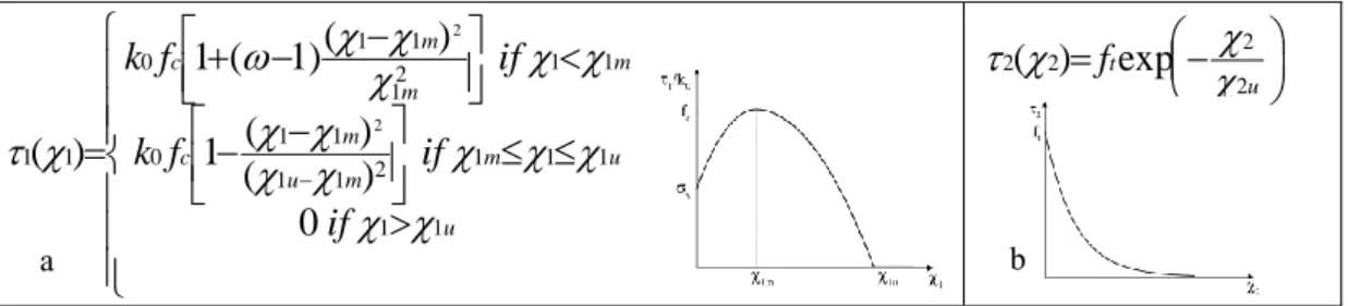
The plasticity model used in the thermo-mechanical computations presented below is based on the model proposed by Feenstra and de Borst [11]. The model has been generalized to 3D problems. The
main reasons to choose this model were: a good description of the tensile and compressive behaviour, the possibility to take into account temperature dependent material parameters and input parameters allowing a simple identification. The stiffness degradation due to cyclic loading is not modelled. The model uses two yield criterions. A Drucker-Prager yield function and a Rankine yield function are used respectively in compression and in tension with the following non linear and exponential hardening laws
1(
1)
and
2(
2)
:
u u m m u m c m m m cif
if
f
k
if
f
k
1 1 1 1 1 2 1 1 1 1 0 1 1 2 1 1 1 0 1 10
)
(
)
(
1
)
(
)
1
(
1
)
(
2 2
u tf
2 2 2 2(
)
exp
Figure 3. Hardening law in compression (a) and in tension (b)
where c y
f
,
yis the yield limit in uniaxial compression andf
c the uniaxial compressive strength.
1,
1m and
1u are the internal hardening parameter in compression, its value at maximum strength and its value when the compressive strength becomes equal to zero,))
1
exp(
1
(
1
2
t f uhf
G
,G
f is the fracture energy,f
t the tensile strength andh
an equivalent length which is a representative dimension of the mesh size. It is assumed thath
A
for a 2D domain and 3V
h
for a 3D domain. Hardening laws are shown in figure 3. The input parameters of the model are Young’s modulus, Poisson’s coefficient, uniaxial and biaxial compressive strengths, yield limit, peak strain and ultimate strain in uniaxial compression, tensile strength and fracture energy.In the example presented in the next paragraph, the parameters are temperature dependent. The evolutions of Young’s modulus and compressive uniaxial strength are given by experimental data, as shown in chapter 2. The biaxial compressive strength is assumed to vary as the uniaxial compressive strength and the yield limit is assumed to vary as Young’s modulus. Poisson’s coefficient, thermal expansion, tensile strength and fracture energy are considered constant.
4. EXPERIMENTAL VALIDATION OF MODELS
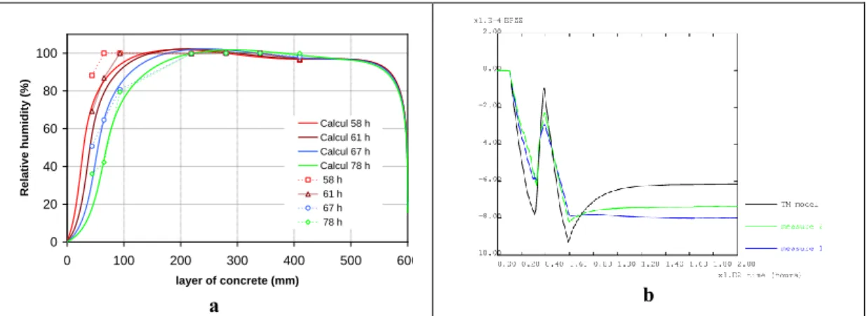
All the tests carried out by the CEA share a high degree of attention to instrumentation, not only thermal and mechanical but also hydric, which is relatively unusual on large-scale structures. This is the case in particular for the MAQBETH test mockup, an annular reinforced concrete structure 2.2 m in diameter fitted with pore pressure sensors and relative humidity sensors; the unit can be heated to an internal temperature of 200°C for periods of several months. The instrumentation has been used to clearly identify water transport mechanisms in concrete in the presence of a strong temperature gradient and structural damage. In the hot compression-loaded zone, transfer in porous media corresponded to the mechanism determined using transport models based on capillary suction pressure and on the pressure of the gas mixture. In the cooler zone, however, water transfer was measured in liquid form via cracks under Darcy flow conditions. We were able to measure the amplitude of the fluid pressures, which did not exceed 10 bars. Hydric measurement data were compared with computations based on input data obtained by characterization of centimeter-scale test specimens (Figure 4a).
a b
Figure 4. Comparison of predicted relative humidity in the layer of concrete versus measurement at different
moments (a) and model predicted vertical strain versus measured strain on the heated surface (b)
Thermo-mechanical computations of the mockup using the plasticity model presented above have been carried out. A two-dimensional axisymmetric model of one half of the mock-up is considered. First a thermal analysis is carried out to determine the temperature distribution history within the structure. A thermo-mechanical analysis is then performed using these temperature fields as thermal loading. The temperature history applied by the heating device is imposed on the internal surface while a zero thermal flux is imposed at the ends because of the thermal insulation.
Temperatures obtained by a thermal analysis are in good agreement with measured temperatures. In the central area of the mock-up the stress state is close to a biaxial state: radial stresses are small compared to vertical and orthoradial stresses. The temperature gradient in the depth of the structure generates compressive stresses near the heated surface and tensile stresses near the external surface. In the compression zone, plastic deformations occur over a width of 8 cm whereas in the tension zone two-thirds of the depth of the structure experiences plastic deformation. Figure 4b shows the comparison of the vertical strains predicted by the thermo-mechanical model against measured strains given by two different gauges. The strain represented is the mechanical strain (total strain minus thermal strain) on the heated surface.
0 20 40 60 80 100 0 100 200 300 400 500 600 layer of concrete (mm) Rela tive humidity (%) Calcul 58 h Calcul 61 h Calcul 67 h Calcul 78 h 58 h 61 h 67 h 78 h
JOURNAL DE PHYSIQUE IV 6
5. APPLICATION TO LONG-TERM INTERIM STORAGE
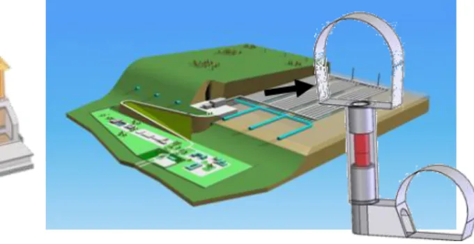
The third research topic of the French 1991 nuclear waste management act covers long-term interim storage. Two options are being investigated for high-level waste packages: surface (Figure 5) and subsurface (Figure 6) storage of two leaktight barrier canisters for spent nuclear fuel or vitrified wasteforms.
The guidelines determined the fundamental design options applicable to the concept and container:
no electromechanical components subject to wear in the storage facility,
safe containment of the radioactive inventory by two barriers constituted by the interim storage containers, the outer barrier being subjected to very slow and predictable corrosion at low relative humidity values,
continuous drainage by gravity of the storage facility,
dry storage and residual thermal power removal by natural air convection flow: transverse air flow in semi-underground vaults for surface storage [1], axial air flow in vertical shafts for
subsurface storage [2].
5.1 Facilities design
The facility is designed to withstand the design-basis earthquake. The modules are capable of withstanding the impact of a fighter plane and ensure the protection of the containers from fire risks (burning kerosene)
The design takes into account the possible overloads arising in operation: thermal loads resulting from the heat released by the containers and mechanical stresses produced in the structure by the kinetics of concrete shrinkage.
The new approach described in this paper was applied to three strategic zones of the storage: the subsurface vault of the upper gallery, the subsurface shaft’s structure and the surface slab.
Figure 5. Example of a surface storage vault Figure 6. Example of a subsurface storage shaft
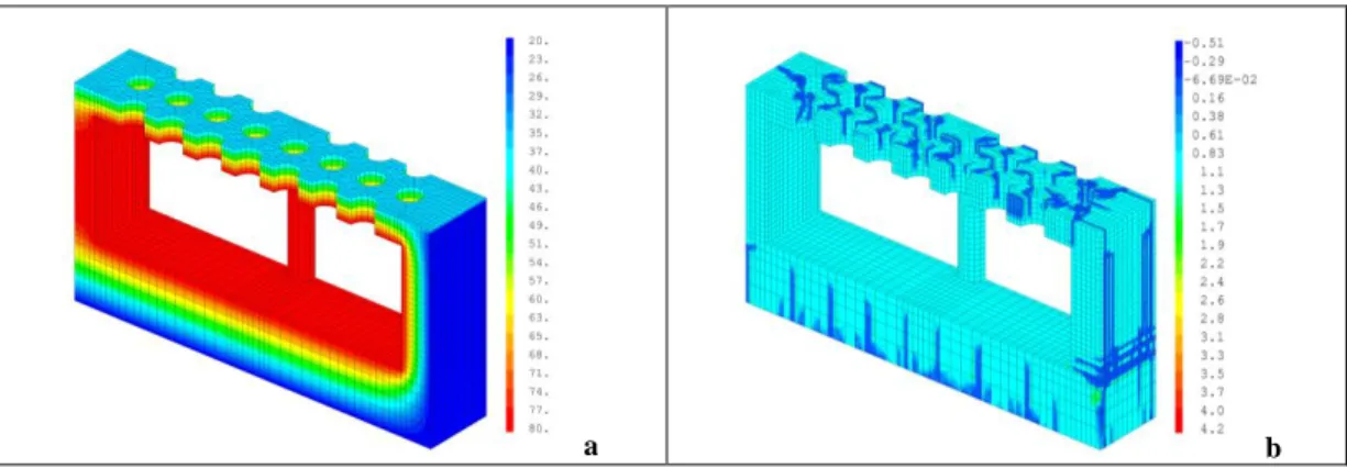
5.2 Surface RC slab's mechanical behaviour
Thermo-mechanical behaviour of the surface’s slab simulation has been carried out. FEM model represents the central part of the structure surrounding the canisters, with two shear walls, the raft foundation and a half- column (Figure 5 and Figure 7a). Reinforcement is taken into account. Figure 7a shows the vault’s temperature field in normal way and Figure 7b, cracking due to tensile force in
cold areas: bottom of the raft, outside of the walls, extrados of the slab and in holes. As shown in Figure 7b, cracking is obtained when the ratio of the flow rule divided by the tensile strength is null.
a b
Figure 7. Vault’s temperature field in normal way (a) and cracking due to tensile force (b)
5.3 Subsurface design study of a concrete shell
Mechanical loading of permanent concrete lining is due to the temperature elevation in limestone and the rock dilatation. The design takes into account the temperature effects in the underground structure in normal at full capacity and in accidental situations.
A design study of a shell for the storage shaft has been carried out based on the regulatory framework of Eurocode 2. In order to optimise the excavation dimensions and the durability of the structure, high performance concrete was selected with a mechanical strength
exceeding 100 MPa, with high stress relaxation properties and stainless steel reinforcement to minimize the wall thickness Thermomechanical calculations were carried out for the shell to assess the impact of the rebars on the stress distribution (Figure 8) in the concrete, to determine the stress concentration zones versus height, and to examine the mechanical impact of different thermal and mechanical loading scenarios.
The reinforcements were found to have a significant effect on the stress distribution, particularly the clips interconnecting the reinforcement layers. In addition, the sequencing was optimised to favour the interpretation of the results by beginning with mechanical loading without thermal loading with, then mechanical loading. This scenario limits damage to the shell and limits concrete cracking. Similar stress states can be obtained with a low heating rate.
JOURNAL DE PHYSIQUE IV 8
6. DEMONSTRATION PROGRAMS 6.1 Galatee
The Galatee gallery is a demonstration tunnel for long-term subsurface storage. The experiments are designed to study the thermo mechanical response over time of the structure under normal operating conditions (corresponding to an interim storage facility loaded to full capacity).
The walls of the vault are heated continuously at 80°C and are instrumented to monitor the temperature and relative humidity of the concrete throughout its thickness in the course of drying. At the end of the test the residual deformation of the arch will compared with its initial geometry by local and topographic measurements.
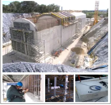
A comparison wall (Figure 9) has been built to be able to allow destructive sampling of structural concrete representative of the construction of the vault.
Figure 9 : Overall view during construction of the vault of GALATEE. View of the instrumentation embedded
and of the comparison wall built during construction
6.2 Perspectives on shaft experimental program
The industrial production of items such as the concrete shell based on the final design requires qualification of its long-term behaviour under high thermal and mechanical loads. A scale 1 test facility would be designed for this purpose.
The qualification test facility would be capable of reproducing the thermal and mechanical loads encountered in long-term interim storage, in normal and accidental situations.
7. CONCLUSION
A new approach has been undertaken to specify the thermal, hydric and mechanical history of these structures. This technical approach is based on three areas of research: material characterization, modelling to identify weaknesses in the structure and validation by experimental tests on heavily instrumented structures subjected to representative loads.
The procedure adopted for long-term interim storage facilities can also be applied to other domains: nuclear reactor containments, civil engineering works exposed to severe thermal and mechanical loading like new bridges or high deep tunnels for instance.
References
[1] Lagrave H. et al. Dossier de synthèse des études d'entrepôts de longue durée - version définitive - entreposage en surface des combustibles usés. CEA Internal Scientific Report (2005), DTEC/2005/4
[2] Lagrave H. et al. Dossier de synthèse des études d'entrepôts de longue durée - version définitive - entreposage en subsurface des combustibles usés. CEA Internal Scientific Report (2005), DTEC/2005/6
[3] Ranc G., Sercombe J., Rodrigues S. Comportement à haute température du béton de structure. Impact de la fissuration sur les transferts hydriques. Revue Française de Génie Civil vol 7 n° 4/2003
[4] Ulm, F.-J., Acker, P., Levy, M., 1999. The channel fire. II: analysis of concrete damage. ASCE Journal of Engineering Mechanics 125(3), pp. 283-289.
[5] A. Noumowe, A., 1995. Effets de hautes températures (20 – 600°C) sur le béton. Cas particulier du béton à hautes performances. PhD Thesis, INSA de Lyon, France.
[6] Bazant, Z. P., Kaplan F., 1996. Concrete at High Temperatures, Material properties and mathematical models. Longman Eds, Concrete Design & Construction series, Harlow, England.
[7] P. Kalifa, P., Menneteau F.-D., Quenard, D., 1999. Spalling and pore pressure in HPC at high temperatures. MRS Meeting, Boston, USA.
[8] Gallé, C., Sercombe, J., Pin, M., Arcier, G., Bouniol, P., 2000. Behaviour of high performance concrete under high temperature (60-450°C) for surface long-term storage: thermo-hydro-mechanical residual properties', MRS Conference, Sydney.
[9] Gallé, C., Sercombe, J., 2001. Permeability and Pore Structure Evolution of Silico-calcareous and Hematite High-strength Concretes Submitted to High Temperatures", Materials and Structures, Vol. 34, n°244, pp. 619-628.
[10] Gallé, C., Pin, M., Ranc, G., Rodrigues, S., 2003. Effect of the heating rate on residual thermo-hydro-mechanical properties of a high-strength concrete in the context of nuclear waste storage. Transaction of the SmiRT 17 conference, H01-1 paper, Prague, Czech Republic.
[11] Feenstra P.H, de Borst R. A composite plasticity model for concrete. Int. J. Solids Structures. Vol 33, n°5, pp 707-730, 1996.
![Figure 1. Effect of thermal treatments on MIP pore access distribution (a) and effective gas permeability (b) for standard and heavy HSC [7, 9]](https://thumb-eu.123doks.com/thumbv2/123doknet/13074502.384422/4.718.53.674.84.288/figure-effect-thermal-treatments-distribution-effective-permeability-standard.webp)